manuals.online logo
Brands
  1. Home
  2. •
  3. Brands
  4. •
  5. red lion
  6. •
  7. Transducer
  8. •
  9. red lion CTL005 Series User manual

red lion CTL005 Series User manual


Inside US: +1 (877) 432-9908 Bulletin No. CTL-D
Outside US: +1 (717) 767-6511 Drawing No. LP0652
www.redlion.net Revised 2018-06-30
-1-
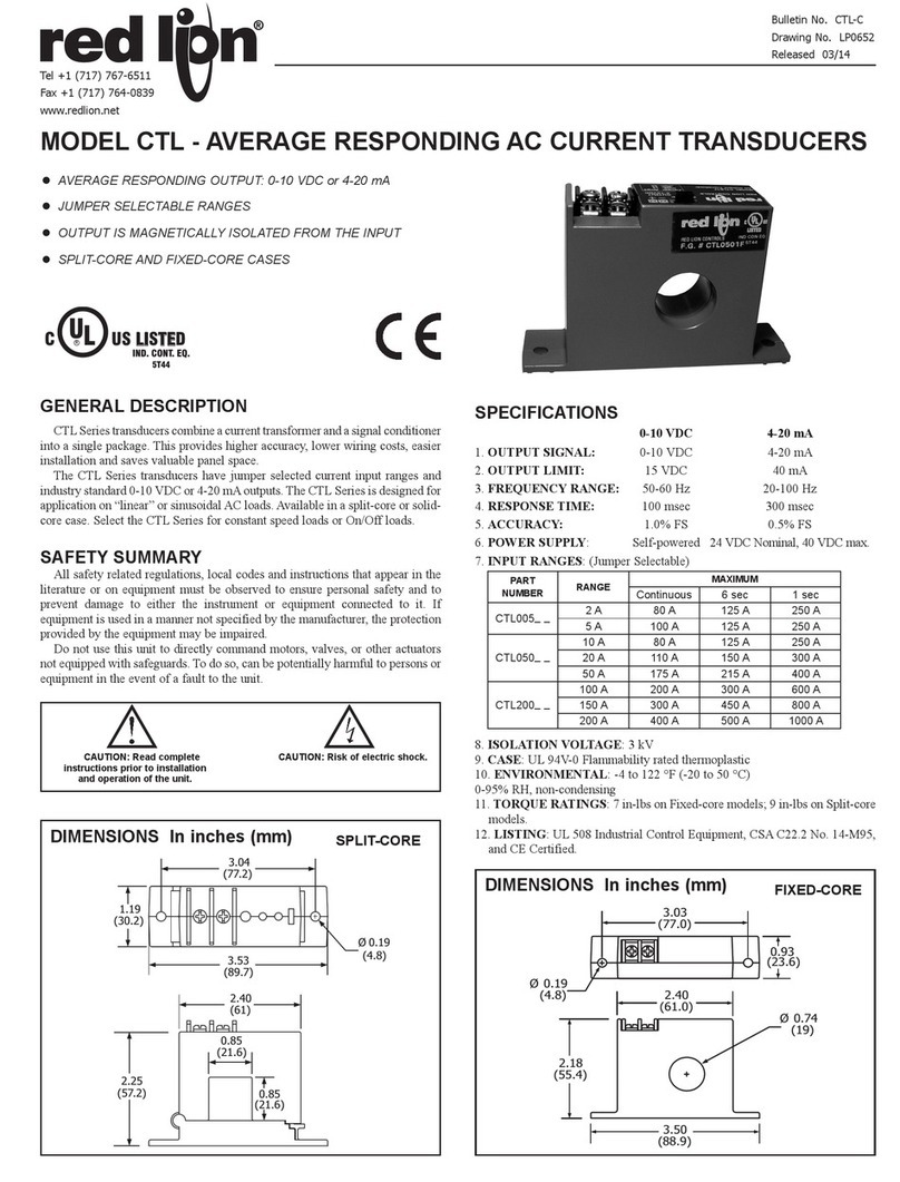
MODELCTL‐AVERAGERESPONDINGACCURRENTTRANSDUCERS
•AVERAGE RESPONDING OUTPUT: 0-10 VDC or 4-20 mA
•JUMPER SELECTABLE RANGES
•OUTPUT IS MAGNETICALLY ISOLATED FROM THE INPUT
•SPLIT-CORE AND FIXED-CORE CASES
GENERALDESCRIPTION
CTL Series transducers combine a current transformer and a signal
conditioner into a single package. This provides higher accuracy, lower
wiring costs, easier installation and saves valuable panel space.
The CTL Series transducers have jumper selected current input ranges
and industry standard 0-10 VDC or 4-20 mA outputs. The CTL Series is
designed for application on “linear” or sinusoidal AC loads. Available in a
split-core or solid-core case. Select the CTL Series for constant speed
loads or On/Off loads.
SAFETYSUMMARY
All safety regulations, local codes and instructions that appear in this
and corresponding literature, or on equipment, must be observed to
ensure personal safety and to prevent damage to either the instrument or
equipment connected to it. If equipment is used in a manner not specified
by the manufacturer, the protection provided by the equipment may be
impaired.
Do not use this unit to directly command motors, valves, or other
actuators not equipped with safeguards. To do so, can be potentially
harmful to persons or equipment in the event of a fault to the unit.
SPECIFICATIONS
1. OUTPUT SIGNAL:
2. OUTPUT LIMIT:
3. FREQUENCY RANGE:
4. RESPONSE TIME:
5. ACCURACY:
6. POWER SUPPLY:
7. INPUT RANGES: (Jumper Selectable)
8. ISOLATION VOLTAGE: 3 kV
9. CASE: UL 94V-0 Flammability rated thermoplastic
10.ENVIRONMENTAL: -4 to 122 °F (-20 to 50 °C)
0-95% RH, non-condensing
11.TORQUE RATINGS: 7 in-lbs on Fixed-core models; 9 in-lbs on Split-
core models.
12. LISTING: UL Listed: File #E191578.
CAUTION: Risk Of Danger.
Read complete instructions prior to
installation and operation of the unit.
CAUTION: Risk of electric shock.
PART
NUMBER RANGE
MAXIMUM
CONTINUOUS 6 SEC 1 SEC
CTL005_ _ 2 A 80 A 125 A 250 A
5 A 100 A 125 A 250 A
CTL050_ _
10 A 80 A 125 A 250 A
20 A 110 A 150 A 300 A
50 A 175 A 215 A 400 A
CTL200_ _
100 A 200 A 300 A 600 A
150 A 300 A 450 A 800 A
200 A 400 A 500 A 1000 A
3.50
(88.9)
3.03
(77.0)
0.93
(23.6)
Ø 0.19
(4.8) 2.40
(61.0)
2.18
(55.4)
Ø 0.74
(19)
DIMENSIONSIninches(mm) FIXED-CORE
CUS LISTED
UL
R
PROC. CONT. EQ.
E191578
0-10 VDC
0-10 VDC
15 VDC
50-60 Hz
100 msec
1.0% FS
Self-powered
4-20 mA
4-20 mA
40 mA
20-100 Hz
300 msec
0.5% FS
24 VDC Norminal, 40 VDC max.
0.85
(21.6)
0.85
(21.6)
3.53
(89.7)
2.40
(61)
3.04
(77.2)
Ø 0.19
(4.8)
2.25
(57.2)
1.19
(30.2)
DIMENSIONSIninches(mm) SPLIT-CORE

-2-
Bulletin No. CTL-D Released 2018-06-30
Drawing No. LP0652
INSTALLATION
Run wire to be monitored through opening in the sensor. The CTL
Series transducers work in the same environment as motors, contactors,
heaters, pull-boxes, and other electrical enclosures. They can be
mounted in any position or hung directly on wires with a wire tie. Just
leave at least one inch (25.4 mm) distance between sensor and other
magnetic devices.
Split‐CoreVersions
Press the tab in the direction as shown to open the sensor. After
placing the wire in the opening, press the hinged portion firmly downward
until a definite click is heard and the tab pops out fully.
KEEPSPLIT‐CORESENSORSCLEAN.
Silicone grease is factory applied on the mating surfaces to prevent rust
and improve performance. Be careful not to allow grit or dirt onto the
grease in the contact area. Operation can be impaired if the mating
surfaces do not have good contact. Check visually before closing.
OUTPUTWIRING
Connect control or monitoring wires to the sensor. Use up to 14 AWG
copper wire and tighten terminals to 7 inch-pounds torque for solid-core
models and 9 inch-pounds torque for split-core models. Be sure the
output load or loop power requirements are met (see diagram).
POWERSUPPLY
CONNECTIONS
RANGESELECT
CTL series transducers feature field selectable ranges. The ranges are
factory calibrated, eliminating time consuming and inaccurate field setting
of zero or span.
1. Determine the normal operating amperage of your monitored circuit
2. Select the range that is equal to or slightly higher than the normal
operating amperage.
3. Place the range jumper in the appropriate position.
TROUBLESHOOTING
0‐10VDCOUTPUTMODELS
1. Sensor Has No Output
A. Polarity is not properly matched. Check and correct wiring polarity.
B. Monitored load is not AC or is not on. Check that the monitored load
is AC and that it is actually on.
C. Split Core models: The core contact area may be dirty. Open the
sensor and clean the contact area.
2. Output Signal Too Low
A. The jumper may be set in a range that is too high for current being
monitored. Move jumper to the correct range.
B. Output load too low. Check output load, be sure that it is at least
100Kand preferably 1 M.
C. Monitored current is below minimum required. Loop the monitored
wire several times through the aperture until the “sensed” current
rises above minimum. Sensed Amps = (Actual Amps) x (Number of
Loops). Count loops on the inside of the aperture.
3. Output Signal Is Always At Maximum
A. Monitored load is not AC or is not on. Check that the monitored load
is AC and that it is actually on.
4‐20mAOUTPUTMODELS
1. Sensor Has No Output
A. Power supply is not properly sized. Check power supply voltage and
current rating.
B. Polarity is not properly matched. Check and correct wiring polarity
C. Split Core models: The core contact area may be dirty. Open the
sensor and clean the contact area.
2. Output Signal Too Low
A. The jumper may be set in a range that is too high for current being
monitored. Move jumper to the correct range.
B. The load current is not sinusoidal.
C. Monitored current is below minimum required. Loop the monitored
wire several times through the aperture until the “sensed” current
rises above minimum. Sensed Amps = (Actual Amps) x (Number of
Loops). Count loops on the inside of the aperture.
3. Sensor Is Always At 4 mA
A. Monitored load is not AC or is not on. Check that the monitored load
is AC and that it is actually on.
4. Output Signal Is Always At 20 mA
A. The jumper may be set in a range that is too low for current being
monitored. Move jumper to the correct range.
ORDERINGINFORMATION
Important!
Keep Contact
Area CLEAN!
To Open
Press Tab
Toward Hinge.
250 1000750
Total Loop Impedance (Ohms)
25
20
15
10
5
Loop Power (VDC)
Operating Range
V
L
= 12VDC + (R
L
×0.020A)
where V
L
= Minimum Loop Supply
R
L
= Total Loop Resistance (Ohms)
500
0
2(+)1(–)
Output
Range Jumper
(+)(–)
24 VDC Power
(+)
(–)
Load
(Controller,
Meter, etc.)
2(+)1(–)
Output
Range Jumper
4–20mA Option
10 VDC Option 1M
:
Recommended
100K
:
Acceptable (Add
Notes: Captive screw terminals.
12–22 AWG solid or stranded.
Observe polarity.
1.3% error for 100 K)
TYPE MODEL NO. DESCRIPTION PART
NUMBER
SPLIT CORE
CTL12S 2-5 A / 4-20 mA CTL0052S
CTL52S 10-50 A / 4-20 mA CTL0502S
CTL22S 100-200 A / 4-20 mA CTL2002S
FIXED CORE
4-20 mA
CTL52F 10-50 A / 4-20 mA CTL0502F
CTL22F 100-200 A / 4-20 mA CTL2002F
FIXED CORE
0-10 VDC
CTL51F 10-50 A / 10 VDC CTL0501F
CTL21F 100-200 A / 10 VDC CTL2001F

This manual suits for next models

4

Other red lion Transducer manuals

red lion CTL12S User manual

red lion

red lion CTL12S User manual

red lion CTR05 User manual

red lion

red lion CTR05 User manual

red lion CTD User manual

red lion

red lion CTD User manual

Popular Transducer manuals by other brands

Simrad ES38DD -  REV E installation manual

Simrad

Simrad ES38DD - REV E installation manual

TE Connectivity AST46DS operating instructions

TE Connectivity

TE Connectivity AST46DS operating instructions

Nexus NX2 installation manual

Nexus

Nexus NX2 installation manual

HP 5501A Operating and service manual

HP

HP 5501A Operating and service manual

WIKA CPT6020 operating instructions

WIKA

WIKA CPT6020 operating instructions

JBL Professional Series Technical manual

JBL

JBL Professional Series Technical manual

Veris Industries PWXN07C installation guide

Veris Industries

Veris Industries PWXN07C installation guide

Thyracont VSP63 operating instructions

Thyracont

Thyracont VSP63 operating instructions

Milltronics EASY AIMER 2 manual

Milltronics

Milltronics EASY AIMER 2 manual

Siedle Novotechnik TP1 CANopen manual

Siedle

Siedle Novotechnik TP1 CANopen manual

Airmar TM185HW Owner's guide and installation instructions

Airmar

Airmar TM185HW Owner's guide and installation instructions

Veris PX3 Series installation guide

Veris

Veris PX3 Series installation guide

TILLQUIST LQT400 user manual

TILLQUIST

TILLQUIST LQT400 user manual

Garmin GT51 Thru-Hull installation instructions

Garmin

Garmin GT51 Thru-Hull installation instructions

Pulsar 3 instruction manual

Pulsar

Pulsar 3 instruction manual

Simrad ES120-25X10 -  REV C datasheet

Simrad

Simrad ES120-25X10 - REV C datasheet

SELVAS Healthcare Braille EDGE 40 user manual

SELVAS Healthcare

SELVAS Healthcare Braille EDGE 40 user manual

B-band A2 installation manual

B-band

B-band A2 installation manual

manuals.online logo
manuals.online logoBrands
  • About & Mission
  • Contact us
  • Privacy Policy
  • Terms and Conditions

Copyright 2025 Manuals.Online. All Rights Reserved.