TILLQUIST LQT400 User manual


i
Thank you for choosing LQT400 from Hugo Tillquist AB!
The LQT400 is a 3-phase multi-transducer with 2 analog outputs that can
be configured to measure any electrical quantity. All areas for AC current
and voltage (True RMS) are covered by one single unit.
Our free transducer configuration software “ConfigLQT” can be used to
easily configure the LQT400 via its USB-port.

ii
Table of contents
Thank you for choosing LQT400 from Hugo Tillquist AB!.........................................i
1Product description...........................................................................................1
1.1 Technical data ...........................................................................................1
2Instructions........................................................................................................2
2.1 Mounting...................................................................................................2
2.2 Installation.................................................................................................2
2.3 Operation ..................................................................................................2
2.4 Warning!....................................................................................................2
2.5 Maintenance .............................................................................................2
2.6 Inputs - Outputs ........................................................................................3
2.7 Symbols on the appliance .........................................................................3
2.8 Installation of ConfigLQT...........................................................................3
3Configuration.....................................................................................................4
3.1 Connection to computer...........................................................................4
3.1.1 Monitored parameters ......................................................................5
3.2 Input settings.............................................................................................5
3.2.1 System connection.............................................................................6
3.3 Analog Outputs .........................................................................................8
3.3.1 Measured quantities..........................................................................9
3.3.2 Example of settings for the analog outputs.....................................10
3.4 Save / Open saved configuration............................................................11
3.4.1 Save a configuration to a file ...........................................................11
3.4.2 Open a configuration from a saved file ...........................................11
4Firmware upgrade...........................................................................................12

1
1Product description
The LQT400 is a configurable 3-phase multi-transducer, capable for measuring any
electrical quantity of a network. It is possible to choose up to 2 of any electrical
quantities and link them to the analog outputs. The configuration is done using our
freeware ConfigLQT via the mini USB-port.
1.1 Technical data
Inputs
Voltage
Input (Un)
100 –400 V main voltage (nominal)
Measuring range
0 –500 V TRMS
Overload
1.5 x Un –continuously, 2 x Un –10 s
Consumption
Un x 1 mA / phase
Frequency
10…40…70…120 Hz
10…15…18…120 Hz (option for 16⅔ Hz)
Current
Input (In)
1 –5 A
Measuring range
0 –10 A TRMS
Overload
2 x In continuously, 10 x In 15 s, 40 x In 1 s
Consumption
< 0.05 VA / phase
AUX Supply
Universal current
24 (2W) –253VDC (3W) (±5%)
80 (4VA) –253VAC (5VA), 50/60 Hz (±5%)
Outputs
Analog
Quantity
2 pcs
Range
+/- 20 mA
Load
max 750 ohm (15V)
Response time
< 100 ms
General data
Accuracy class
0.2
Overvoltage category
CAT III
Max rated values
519 V (L-L) / 300 V (L-N), 10 A
Galvanic insulation
All connections are galvanically separated
USB
1 pc for configuration
Temperature range
-10 to +55 °C (operation), -40 to +70 °C (storage)
Temperature coefficient < 0.1% / 10 °C
Humidity
< 80%
Test voltage
4 kV, 50 Hz, 1 min.
Pollution degree
2
IP Class
Housing IP40, terminals IP20
Dimensions (W x H x D)
70 x 132 x 137 mm –DIN-rail
Mounting
Indoors - Up to 2000 meters height
Weight
~0.5 kg
Standards
SS-EN 60688 Transducers
SS-EN 61010-1, 61010-2-030 Safety
EN 61000-6-2, -6-4, -6-5 EMC

2
2Instructions
2.1 Mounting
The transducer is mounted on a 35mm DIN rail on a wall or device cabinet for suitable
protection. The enclosure shall not be accessible without tools.
2.2 Installation
The installation is to be made by competent personnel and in accordance with
applicable regulations. Before installation please check that the transducer has the
correct type and complies with the installation needs. The connection to the transducer
is done through the terminals that are designed for a maximum of 6 mm² cable in
accordance with connection diagram. An external switch shall be used so that the unit
can be deenergized during disassembly. It shall be appropriately positioned, easy to
reach and marked as a switch for the transducer. The measuring circuits from the
current transformers must be short-circuited before disconnection. The unit must be
protected against possible overcurrent by automatic circuit breaker.
2.3 Operation
The transducer is intended for operation at an altitude not exceeding 2000m and in an
environment that is not considered as wet location.
2.4 Warning!
Connection must comply with current regulations for systems with rated voltage up to
1000 V.
Before switching on or off and if the housing is removed, all voltages to the appliance
must be switched off.
2.5 Maintenance
The transducer requires no maintenance. Any repairs shall be performed by trained
personnel or the appliance shall be returned to the supplier for repair.
Function and safety are only guaranteed if the instructions in this manual are followed.
3
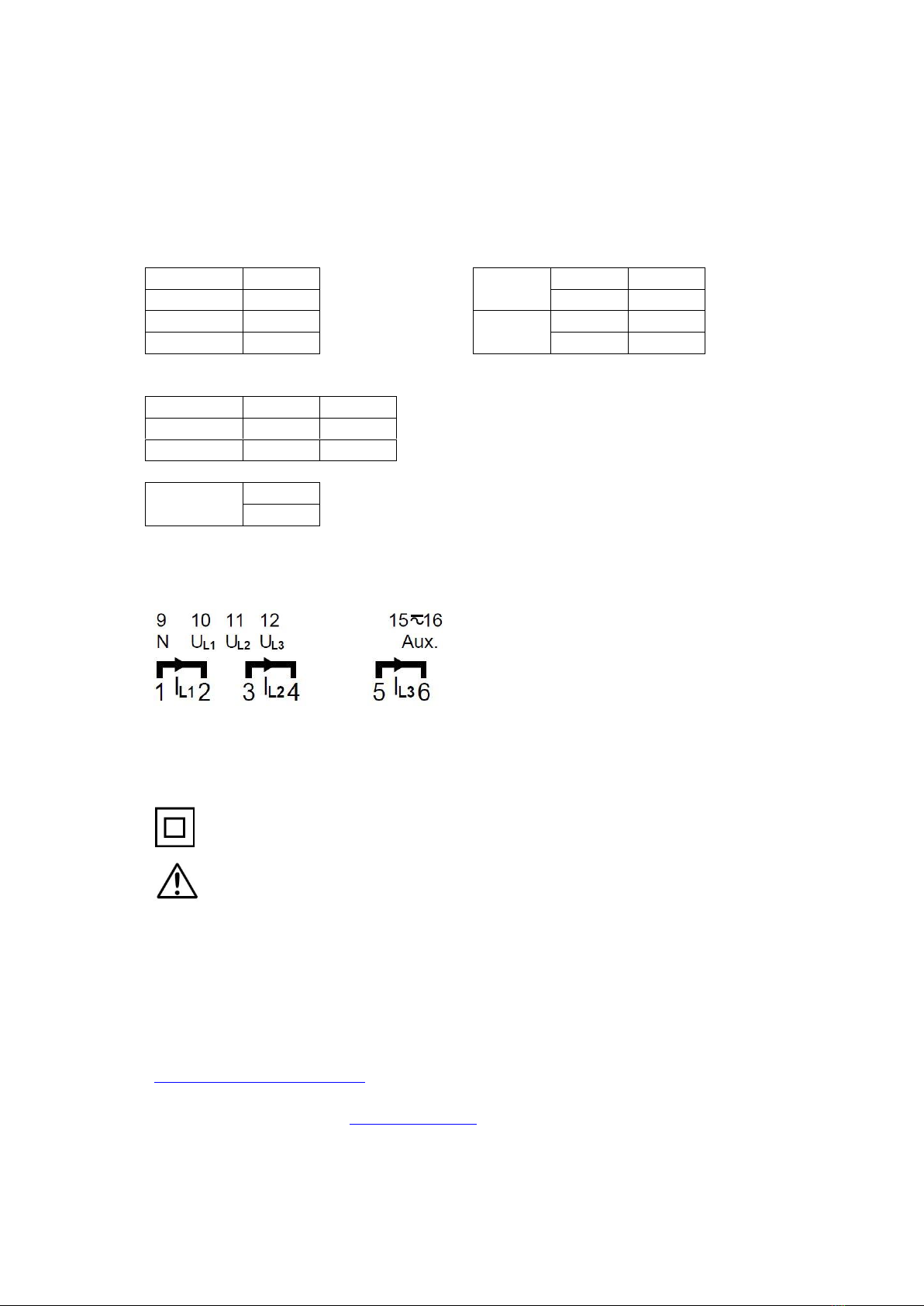
2.6 Inputs - Outputs
Inputs
Analog outputs
Nr
Chanel
Nr
-/+
U1
10
A1
13
-
U2
11
14
+
U3
12
A2
7
-
N
9
8
+
IN
OUT
I1
1
2
I2
3
4
I3
5
6
AUX
SUPPLY
15
16
Terminal diagram
2.7 Symbols on the appliance
Double insulated device.
Warning for life-threatening or hazardous for properties situations.
2.8 Installation of ConfigLQT
The installation kit consists of the configuration software and a driver for the USB
connection to LQT400. ”.NET Framework”version 4.0 is a software from Microsoft,
usually installed by default, that is necessary for the proper operation of ConfigLQT. If
not already installed, it can be downloaded by the following link:
http://www.microsoft.com/net/.
Download ConfigLQT from www.tillquist.com, unzip the files and install it by running
setup.

4
3Configuration
3.1 Connection to computer
Connect a USB-cable between the USB-port on LQT400 and the computer. Use a cable
with contacts type A and mini B. No safety action is required while connecting the USB
cable to the device.
Start ConfigLQT and click Connect.
The connection status will change to Connected with a green background and
information about the transducer will be displayed once the connection is established.
Various basic parameters of the transducer as well as the measured values are displayed
on the screen when the transducer is connected to a measuring object. The measured
values can be shown as Primary or Secondary values.
The measuring range covered by LQT 400 is ‘Wide’which means that the transducer can
be connected to networks with a nominal main voltage between 100 and 400 V AC and a
nominal current between 1 and 5 A. Using the ConfigLQT it is possible to configure the
transducer in order to be used for all different connections in 1-phase and 3-phase
networks shown on page 6.
5
3.1.1 Monitored parameters
P
Power
P=S*cos(φ) [W]
IS
System current with sign
Q
Reactive power
Q=S*sin(φ) [var]
PF
Power factor
PF=P/S
S
Apparent power
S=rot(3)*Uh*Ih [VA]
QF
Reactive power factor
QF=Q/S
U
Voltage
LF
= sign(Q)*(1-|PF|)
I
Current
PA
Phase angle
F
Frequency
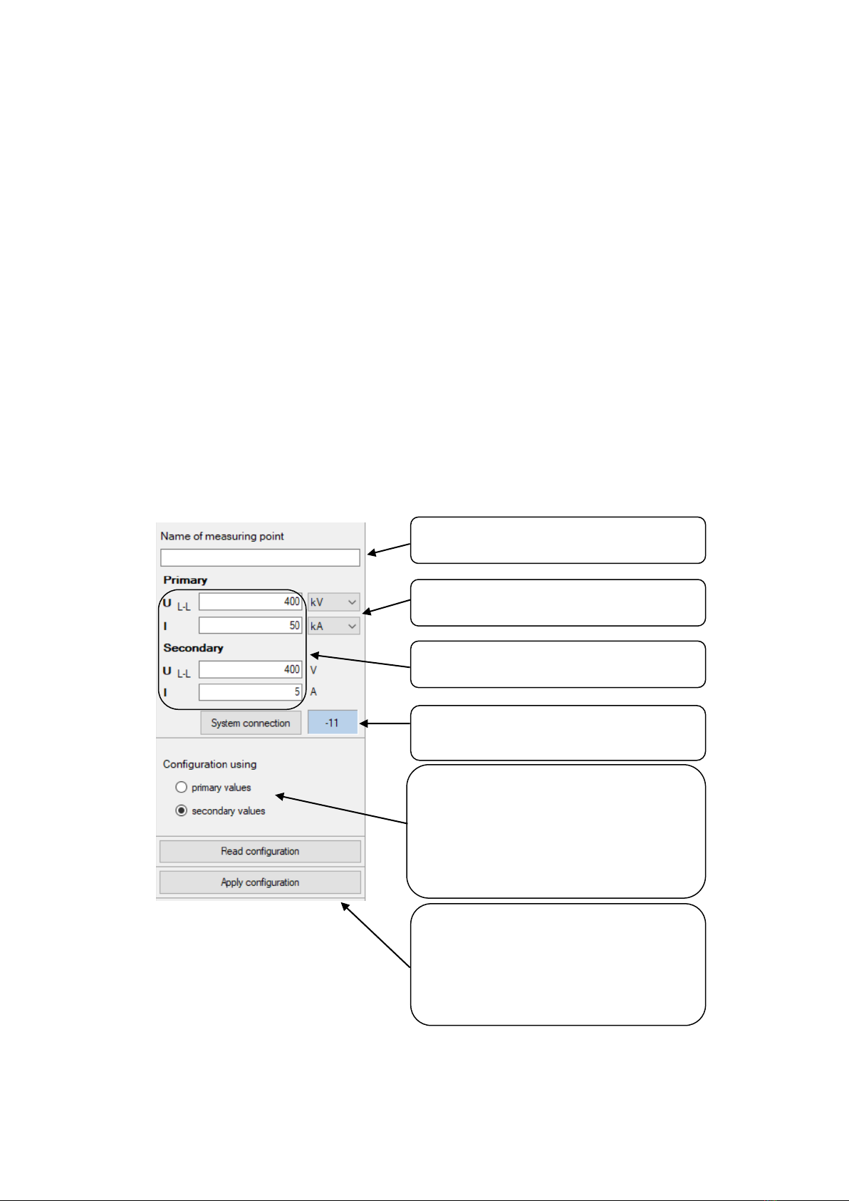
3.2 Input settings
Read configuration: Read present settings
from LQT400 to ConfigLQT.
Apply configuration: Save data to LQT400.
Configuration using: choose which values will
be shown.
•Primary values –values based on
primary data.
•Secondary values –values based on
secondary values.
Primary: U: V, kV, MV
I: A, kA
Name of measuring point
Free text –20 characters
System connection: For more information see
page 6.
Transformer ratio
6
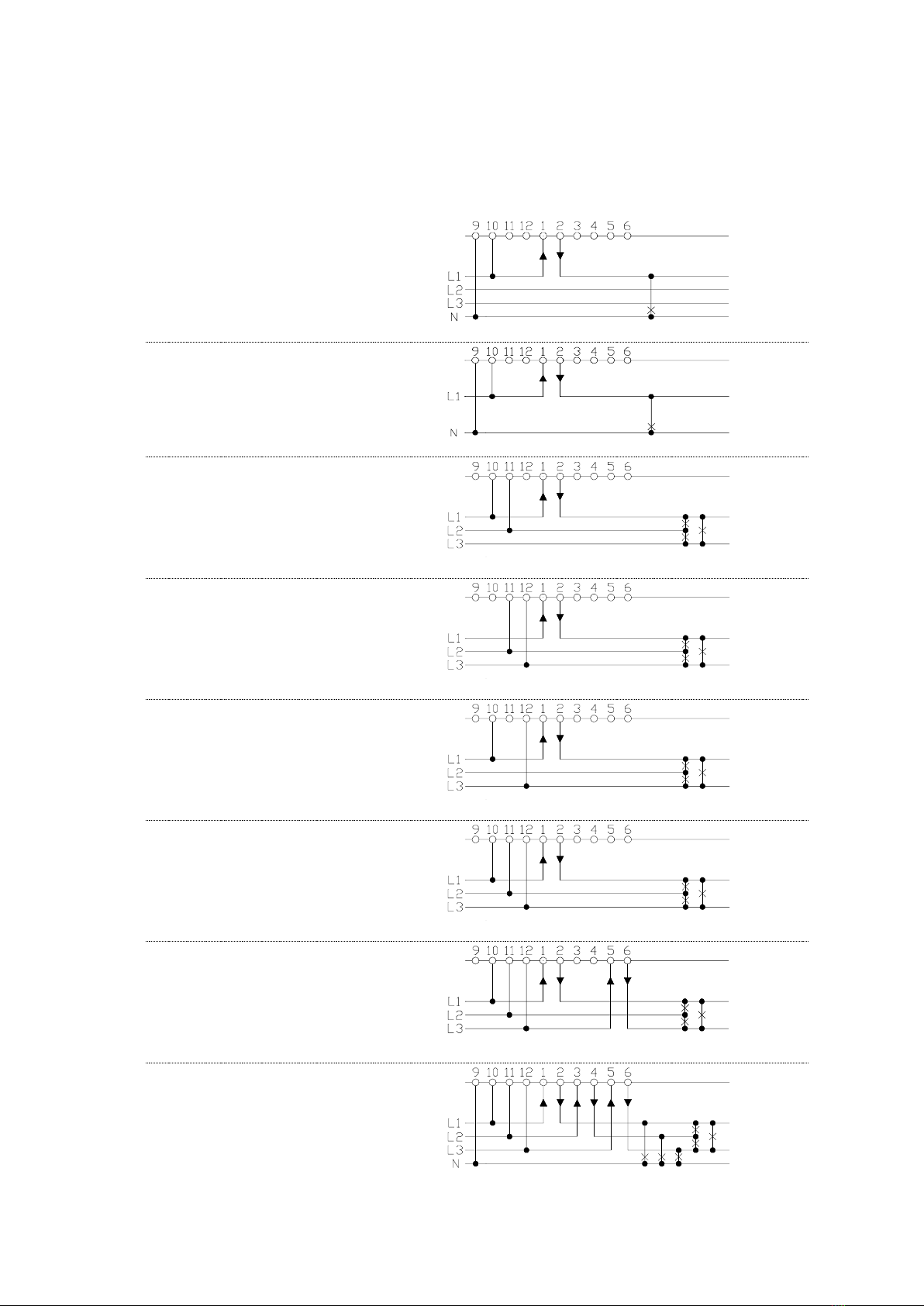
3.2.1 System connection
Select the appropriate diagram for the used network.
-00
3-phase
1 system
3-phase symmetrical load
-01
1-phase
1 system
-02
3-phase
1 system
3-phase symmetrical load
-03
3-phase
1 system
3-phase symmetrical load
-04
3-phase
1 system
3-phase symmetrical load
-05
3-phase
1 system
3-phase symmetrical load
-09
3-phase
2 systems
3-phase asymmetrical load
-11
3-phase
3 systems
3-phase asymmetrical load

7
System
connection
Application
I1
I2
I3
N
U1
U2
U3
U12
U23
U31
U =
I =
P =
Q =
S =
-00
4 wires
3-phase symmetrical load
X
-
-
X
X
-
-
-
-
-
U1
I1
P1*3
Q1*3
S1*3
-01
1 wire
1 phase
X
-
-
X
X
-
-
-
-
-
U1
I1
P1
Q1
S1
-02
3 wires
3-phase symmetrical load
X
-
-
-
-
-
-
X
-
-
-
-
PI1U12
QI1U12
I1*U12*√3
-03
3 wires
3-phase symmetrical load
X
-
-
-
-
-
-
-
X
-
-
-
PI1U23
QI1U23
I1*U23*√3
-04
3 wires
3-phase symmetrical load
X
-
-
-
-
-
-
-
-
X
-
-
PI1U31
QI1U32
I1*U31*√3
-05
3 wires
3-phase symmetrical load
X
-
-
-
X
X
X
X
X
X
-
I1
P1*3
Q1*3
S1*3
-09
3 wires
3-phase asymmetrical
load
X
-
X
-
X
X
X
X
X
X
-
(I1+I3)*3/2
(P1+P3)*3/2
(Q1+Q3)*3/2
(S1+S3)*3/2
-11
4 wires
3-phase asymmetrical
load
X
X
X
X
X
X
X
X
X
X
(U1+U2+U3)/3
(I1+I2+I3)/3
P1+P2+P3
Q1+Q2+Q3
S1+S2+S3
-11
4 wires
3-phase asymmetrical
load
Open Delta
X
X
X
-
X
X
X
X
X
X
(U1+U2+U3)/3
(I1+I2+I3)/3
P1+P2+P3
Q1+Q2+Q3
S1+S2+S3

8
3.3 Analog Outputs
Click Analog Outputs tab to configure the analog outputs.
The analog outputs can be freely configured to the desired measured quantity within
the allowed measuring ranges. Select the quantity you want to measure using the drop-
down list. In the Input Secondary field the start values are to be written in the first
space, any breakpoints afterwards and the end value at last. Under Output Value the
corresponding values of the output signal are indicated.
Click Apply configuration to transfer and save the new settings in the transducer.
To simulate the outputs for testing purposes, please choose Fixed Output, fill in the
desired value and click Apply configuration.
Activation of an analog output.
Drop-down list for selection of
measured values and desired
rows for the results .

9
3.3.1 Measured quantities
Prefix
Quantity
Calculation
System / Phase
I
Input current
(I1+I2+I3)/3
System
I1
Phase current L1
L1
I2
Phase current L2
L2
I3
Phase current L3
L3
U
Input voltage
(U1+U2+U3)/3
System
U1
L1 Phase voltage
L1
U2
L2 Phase voltage
L2
U3
L3 Phase voltage
L3
P
Active power
P1+P2+P3
System
P1
Active power L1
L1
P2
Active power L2
L2
P3
Active power L3
L3
Q
Reactive power
Q1+Q2+Q3
System
Q1
Reactive power L1
L1
Q2
Reactive power L2
L2
Q3
Reactive power L3
L3
S
Apparent power
S1+S2+S3
System
S1
Apparent power L1
L1
S2
Apparent power L2
L2
S3
Apparent power L3
L3
U12
Main voltageL1-L2
L1 - L2
U23
Main voltage L2-L3
L2 - L3
U31
Main voltage L3-L1
L3 - L1
PF
Active power factor
P/S
System
PF1
Active power factor
COS(φ1)=P1/S1
L1
PF2
Active power factor
COS(φ2)=P2/S2
L2
PF3
Active power factor
COS(φ3)=P3/S3
L3
QF
Reactive power factor
Q/S
System
QF1
Reactive power factor
SIN(φ1)=Q1/S1
L1
QF2
Reactive power factor
SIN(φ2)=Q2/S2
L2
QF3
Reactive power factor
SIN(φ3)=Q3/S3
L3
LF
LF factor
sign(Q)*(1-|PF|)
System
LF1
LF factor
sign(Q1)*(1-|PF1|)
L1
LF2
LF factor
sign(Q2)*(1-|PF2|)
L2
LF3
LF factor
sign(Q3)*(1-|PF3|)
L3
PA
Phase angel
PA=(PA1+PA2+PA3)/3
System
PA1
Phase angel
φ1=ARCCOS(P1/S1)/PI*180*sign(P1)
L1
PA2
Phase angel
φ2=ARCCOS(P2/S2)/PI*180*sign(P2)
L2
PA3
Phase angel
φ3=ARCCOS(P3/S3)/PI*180*sign(P3)
L3
IS
Input current with sign
(IS1+IS2+IS3)/3
System
IS1
Phase current with sign
I1*sign(P1)
L1
IS2
Phase current with sign
I2*sign(P2)
L2
IS3
Phase current with sign
I3*sign(P3)
L3
P_I1_U12
Active power, System connection-02
System
P_I1_U23
Active power, System connection -03
System
P_I1_U31
Active power, System connection -04
System
Q_I1_U12
Reactive power, System connection -02
System
Q_I1_U23
Active power, System connection -03
System
Q_I1_U31
Active power, System connection -04
System
F
Frequency
System
Fixed Output
Fixed output

10
3.3.2 Example of settings for the analog outputs
U12
Measuring main voltage
L1-L2
IN: 0 –137,5 V
OUT: 4 –20 mA
Secondary
Analog out
0
4
137,5
20
I1
Measuring current I1
IN: 0 –5 A
OUT: 0 –20 mA
Secondary
Analog out
0
0
5
20
P
Measuring total power
IN: ±50 MW
OUT: ±20 mA
Primary
Analog out
-50000
-20
50000
20
Q
Measuring total power
IN: ±28 MVar
OUT: ±20 mA
Primary
Analog out
-28000
-20
28000
20
U12
Measuring main voltage
L1-L2 with voltlup.
IN: 0-90-137,5 V
OUT: 4-8-20 mA
Secondary
Analog out
0
4
90
8
137,5
20
F
Measuring frequency
45 –55 Hz
IN: 45 –55 Hz
OUT: 4 –20 mA
Secondary
Analog out
45
4
55
20

11
3.4 Save / Open saved configuration
The saved parameters of LQT400 can be saved to a file which can easily be downloaded
to other transducers.
3.4.1 Save a configuration to a file
1. Select File menu and click Save as. .
2. Write a file name and choose a desired folder.
3. Click Save.
3.4.2 Open a configuration from a saved file
1. Select File menu and click Open file.
2. Choose the desired configuration file (XML-document).
3. Click Open.

12
4Firmware upgrade
The LQT400 firmware can be upgraded with the software ConfigLQT. To do so, connect
the transducer to the computer with a USB cable.
1. Start ConfigLQT.
2. Select Firmware Upgrade from Transducer menu.
3. Choose the file with the new firmware and Upgrade.
4. When the upgrade is done, the auxiliary voltage must be disconnected so that
the transducer restarts, allowing the new firmware to take effect.
5. Check that the right firmware version is displayed among the transducer’s data.
Table of contents
Other TILLQUIST Transducer manuals


Popular Transducer manuals by other brands


MKS
MKS 107B manual

Siemens
Siemens 7XV5653-0BA00 operating instructions

GEM
GEM 3140 X Series operating instructions

Meggitt
Meggitt Whittaker C327598 Installation and operation manual

Siedle
Siedle Novotechnik TP1 CANopen user manual

Alcatel Vacuum Technology
Alcatel Vacuum Technology BARATRON 622A instruction manual


