manuals.online logo
Brands
  1. Home
  2. •
  3. Brands
  4. •
  5. Veris
  6. •
  7. Transducer
  8. •
  9. Veris PX3 Series User manual

Veris PX3 Series User manual

Installation Guide
Pressure Monitoring
Installation Guide
Pressure Monitoring
Installation Guide
Pressure Monitoring
Installation Guide
Pressure Monitoring
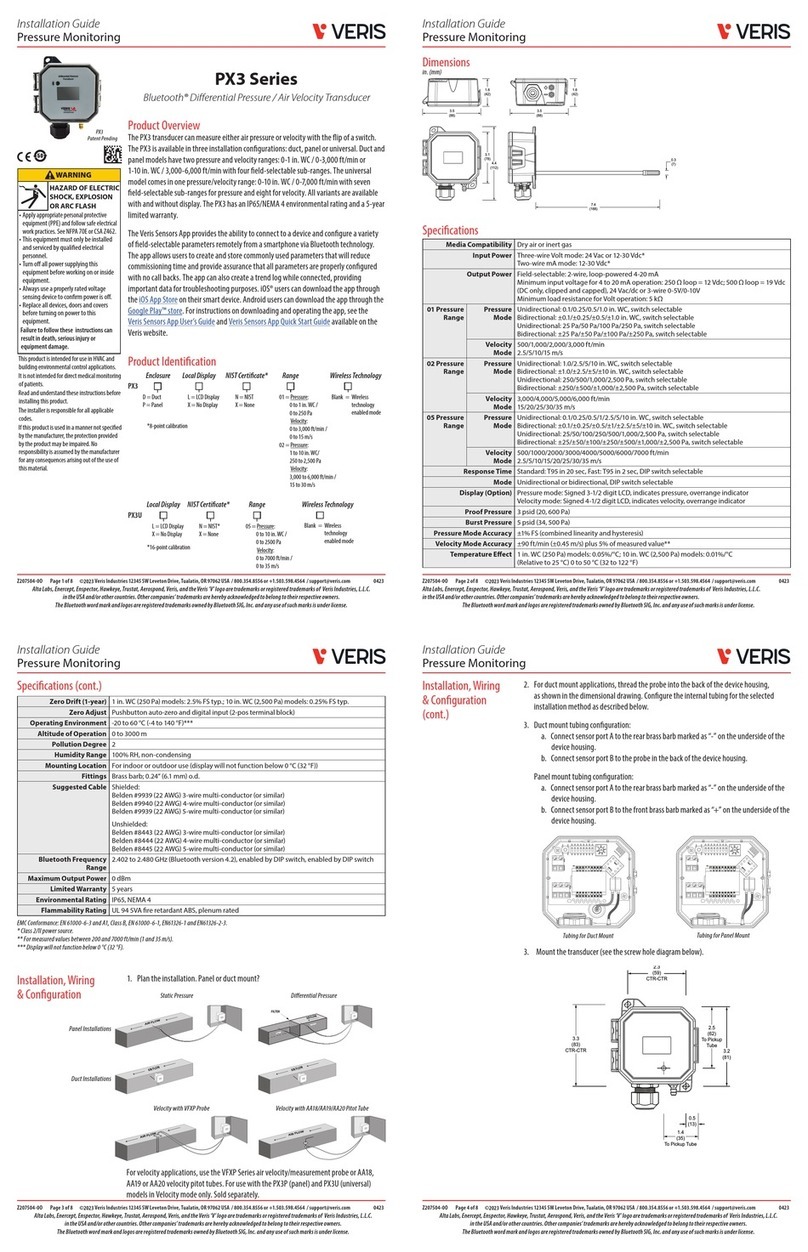
PX3 Series
Differential Pressure / Air Velocity Transducer
PX3
Media Compatibility Dry air or inert gas
Input Power Three-wire Volt mode: 24 Vac or 12-30 Vdc*
Two-wire mA mode: 12-30 Vdc*
Output Power Field-selectable: 2-wire, loop-powered 4-20 mA
Minimum input voltage for 4 to 20 mA operation: 250 Ω loop = 12 Vdc; 500 Ω loop = 19 Vdc
(DC only, clipped and capped), 24 Vac/dc or 3-wire 0-5V/0-10V
Minimum load resistance for Volt operation: 5 kΩ
Pressure
Range 1
Pressure
Mode
Unidirectional: 0.1/0.25/0.5/1.0 in. WC, switch selectable
Bidirectional: ±0.1/±0.25/±0.5/±1.0 in. WC, switch selectable
Unidirectional: 25 Pa/50 Pa/100 Pa/250 Pa, switch selectable
Bidirectional: ±25 Pa/±50 Pa/±100 Pa/±250 Pa, switch selectable
Velocity
Mode
500/1,000/2,000/3,000 ft/min
2.5/5/10/15 m/s
Pressure
Range 2
Pressure
Mode
Unidirectional: 1.0/2.5/5/10 in. WC, switch selectable
Bidirectional: ±1.0/±2.5/±5/±10 in. WC, switch selectable
Unidirectional: 250/500/1,000/2,500 Pa, switch selectable
Bidirectional: ±250/±500/±1,000/±2,500 Pa, switch selectable
Velocity
Mode
3,000/4,000/5,000/6,000 ft/min
15/20/25/30/35 m/s
Pressure
Range 5
Pressure
Mode
Unidirectional: 0.1/0.25/0.5/1/2.5/5/10 in. WC, switch selectable
Bidirectional: ±0.1/±0.25/±0.5/±1/±2.5/±5/±10 in. WC, switch selectable
Unidirectional: 25/50/100/250/500/1,000/2,500 Pa, switch selectable
Bidirectional: ±25/±50/±100/±250/±500/±1,000/±2,500 Pa, switch selectable
Velocity
Mode
500/1000/2000/3000/4000/5000/6000/7000 ft/min
2.5/5/10/15/20/25/30/35 m/s
Response Time Standard: T95 in 20 sec, Fast: T95 in 2 sec, DIP switch selectable
Mode Unidirectional or bidirectional, DIP switch selectable
Display (Option) Pressure mode: Signed 3-1/2 digit LCD, indicates pressure, overrange indicator
Velocity mode: Signed 4-1/2 digit LCD, indicates velocity, overrange indicator
Proof Pressure 3 psid (20, 600 Pa)
Burst Pressure 5 psid (34, 500 Pa)
Pressure Mode Accuracy ±1% FS (combined linearity and hysteresis)
Velocity Mode Accuracy ±90 ft/min (±0.45 m/s) plus 5% of measured value**
Temperature Eect 1 in. WC (250 Pa) models: 0.05%/°C; 10 in. WC (2,500 Pa) models: 0.01%/°C
(Relative to 25 °C) 0 to 50 °C (32 to 122 °F)
Specications
Z208537-0A Page 3 of 8 ©2023 Veris Industries 12345 SW Leveton Drive, Tualatin, OR 97062 USA / 800.354.8556 or +1.503.598.4564 / support@veris.com 0523
Alta Labs, Enercept, Enspector, Hawkeye, Trustat, Aerospond, Veris, and the Veris ‘V’ logo are trademarks or registered trademarks of Veris Industries, L.L.C.
in the USA and/or other countries. Other companies’ trademarks are hereby acknowledged to belong to their respective owners.
Z208537-0A Page 1 of 8 ©2023 Veris Industries 12345 SW Leveton Drive, Tualatin, OR 97062 USA / 800.354.8556 or +1.503.598.4564 / support@veris.com 0523
Alta Labs, Enercept, Enspector, Hawkeye, Trustat, Aerospond, Veris, and the Veris ‘V’ logo are trademarks or registered trademarks of Veris Industries, L.L.C.
in the USA and/or other countries. Other companies’ trademarks are hereby acknowledged to belong to their respective owners.
Z208537-0A Page 4 of 8 ©2023 Veris Industries 12345 SW Leveton Drive, Tualatin, OR 97062 USA / 800.354.8556 or +1.503.598.4564 / support@veris.com 0523
Alta Labs, Enercept, Enspector, Hawkeye, Trustat, Aerospond, Veris, and the Veris ‘V’ logo are trademarks or registered trademarks of Veris Industries, L.L.C.
in the USA and/or other countries. Other companies’ trademarks are hereby acknowledged to belong to their respective owners.
Z208537-0A Page 2 of 8 ©2023 Veris Industries 12345 SW Leveton Drive, Tualatin, OR 97062 USA / 800.354.8556 or +1.503.598.4564 / support@veris.com 0523
Alta Labs, Enercept, Enspector, Hawkeye, Trustat, Aerospond, Veris, and the Veris ‘V’ logo are trademarks or registered trademarks of Veris Industries, L.L.C.
in the USA and/or other countries. Other companies’ trademarks are hereby acknowledged to belong to their respective owners.
Product Identication
Dimensions
Product Overview
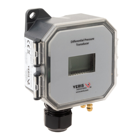
The PX3 transducer can measure either air pressure or velocity with the ip of a switch.
The PX3 is available in three installation congurations: duct, panel or universal. Duct and
panel models have two pressure and velocity ranges: 0-1 in. WC / 0-3,000 ft/min or
1-10 in. WC / 3,000-6,000 ft/min with four eld-selectable sub-ranges. The universal
model comes in one pressure/velocity range: 0-10 in. WC / 0-7,000 ft/min with seven
eld-selectable sub-ranges for pressure and eight for velocity. All variants are available
with and without display. The PX3 has an IP65/NEMA 4 environmental rating and a 5-year
limited warranty.
in. (mm)
PX3
Enclosure
Enclosure
Local Display
D = Duct
P = Panel
U = Universal
L = LCD Display
X = No Display
S
S
Standard,
no wireless
technology
Standard,
no wireless
technology
=
=
NIST Cert* Accuracy Range
Wireless
Technology
Wireless
Technology
N = NIST
X = None
0 = 1%
0 S
S
*8-point calibration
PX3
Local Display
L = LCD Display
X = No Display
NIST Cert* Accuracy Range
N = NIST*
X = None
0 = 1% 5 = Pressure:
0 to 10 in.WC /
0 to 2500 Pa
Velocity:
0 to 7000 ft/min /
0 to 35 m/s
*16-point calibration
1.6
(42)
1.6
(42)
3.5
(88)
3.5
(88)
4.4
(112)
7.4
(188)
0.
3
(7
)
3.1
(78)
Specications (cont.)
Zero Drift (1-year) 1 in. WC (250 Pa) models: 2.5% FS typ.; 10 in. WC (2,500 Pa) models: 0.25% FS typ.
Zero Adjust Pushbutton auto-zero and digital input (2-pos terminal block)
Operating Environment -20 to 60 °C (-4 to 140 °F)***
Altitude of Operation 0 to 3000 m
Pollution Degree 2
Humidity Range 100% RH, non-condensing
Mounting Location For indoor or outdoor use (display will not function below 0 °C (32 °F))
Fittings Brass barb; 0.24” (6.1 mm) o.d.
Suggested Cable Shielded:
Belden #9939 (22 AWG) 3-wire multi-conductor (or similar)
Belden #9940 (22 AWG) 4-wire multi-conductor (or similar)
Belden #9939 (22 AWG) 5-wire multi-conductor (or similar)
Unshielded:
Belden #8443 (22 AWG) 3-wire multi-conductor (or similar)
Belden #8444 (22 AWG) 4-wire multi-conductor (or similar)
Belden #8445 (22 AWG) 5-wire multi-conductor (or similar)
Limited Warranty 5 years
Environmental Rating IP65, NEMA 4
Flammability Rating UL 94 5VA re retardant ABS, plenum rated
Installation, Wiring
& Conguration
FILTER
LOW HIGH
AIR FLOW
AIR FLOW
AIR FLOW
AIR FLOW
Static Pressure
Panel Installations
Duct Installations
Dierential Pressure
1. Plan the installation. Panel or duct mount?
For velocity applications, use the VFXP Series air velocity/measurement probe or AA18,
AA19 or AA20 velocity pitot tubes. For use with the PX3P (panel) and PX3U (universal)
models in Velocity mode only. Sold separately.
2. For duct mount applications, thread the probe into the back of the device housing, as
shown in the dimensional drawing.
3. Congure the internal tubing for the selected installation method as described below.
Duct mount tubing conguration:
a. Connect sensor port A to the rear brass barb marked as “-” on the underside of the
device housing.
b. Connect sensor port B to the probe in the back of the device housing.
Panel mount tubing conguration:
a. Connect sensor port A to the rear brass barb marked as “-” on the underside of the
device housing.
b. Connect sensor port B to the front brass barb marked as “+” on the underside of the
device housing.
AIR FLOW
Velocity with VFXP Probe Velocity with AA18/AA19/AA20 Pitot Tube
AIR FLOW
Installation, Wiring
& Conguration
(cont.)
Tubing for Duct Mount Tubing for Panel Mount
4. Mount the transducer (see the screw hole diagram below).
2.3
(59)
CTR-CTR
3.3
(83)
CTR-CT
R
2.5
(62)
To Pickup
Tube
1.4
(35)
To Pickup Tube
0.5
(13)
3.2
(81)
in. (mm)
50
EMC Conformance: EN 61000-6-3 and A1, Class B, EN 61000-6-1, EN61326-1 and EN61326-2-3.
* Class 2/II power source.
** For measured values between 200 and 7000 ft/min (1 and 35 m/s).
*** Display will not function below 0 °C (32 °F).
WARNING
•
Apply appropriate personal protective
equipment (PPE) and follow safe electrical
work practices. See NFPA 70E or CSA Z462.
• This equipment must only be installed
and serviced by qualied electrical
personnel.
• Turn o all power supplying this
equipment before working on or inside
equipment.
• Always use a properly rated voltage
sensing device to conrm power is o.
• Replace all devices, doors and covers
before turning on power to this
equipment.
This product is intended for use in HVAC and
building environmental control applications.
It is not intended for direct medical monitoring
of patients.
Read and understand these instructions before
installing this product.
The installer is responsible for all applicable
codes.
If this produc
t is used in a manner not specied
by the manufacturer, the protection provided
by the product may be impaired. No
responsibility is assumed by the manufacturer
for any consequences arising out of the use of
this material.
HAZARD OF ELECTRIC
SHOCK, EXPLOSION
OR ARC FLASH
Failure to follow these instructions can
result in death, serious injury or
equipment damage.
1 = Pressure:
0 to 1 in.WC /
0 to 250 Pa
Velocity:
0 to 3,000 ft/min /
0 to 15 m/s
2 = Pressure:
1 to 10 in.WC/
250 to 2,500 Pa
Velocity:
3,000 to 6,000 ft/min /
15 to 30 m/s
50
U
Installation Guide
Pressure Monitoring
Installation Guide
Pressure Monitoring
Installation Guide
Pressure Monitoring
Installation Guide
Pressure Monitoring
Z208537-0A Page 5 of 8 ©2023 Veris Industries 12345 SW Leveton Drive, Tualatin, OR 97062 USA / 800.354.8556 or +1.503.598.4564 / support@veris.com 0523
Alta Labs, Enercept, Enspector, Hawkeye, Trustat, Aerospond, Veris, and the Veris ‘V’ logo are trademarks or registered trademarks of Veris Industries, L.L.C.
in the USA and/or other countries. Other companies’ trademarks are hereby acknowledged to belong to their respective owners.
Z208537-0A Page 6 of 8 ©2023 Veris Industries 12345 SW Leveton Drive, Tualatin, OR 97062 USA / 800.354.8556 or +1.503.598.4564 / support@veris.com 0523
Alta Labs, Enercept, Enspector, Hawkeye, Trustat, Aerospond, Veris, and the Veris ‘V’ logo are trademarks or registered trademarks of Veris Industries, L.L.C.
in the USA and/or other countries. Other companies’ trademarks are hereby acknowledged to belong to their respective owners.
Z208537-0A Page 8 of 8 ©2023 Veris Industries 12345 SW Leveton Drive, Tualatin, OR 97062 USA / 800.354.8556 or +1.503.598.4564 / support@veris.com 0523
Alta Labs, Enercept, Enspector, Hawkeye, Trustat, Aerospond, Veris, and the Veris ‘V’ logo are trademarks or registered trademarks of Veris Industries, L.L.C.
in the USA and/or other countries. Other companies’ trademarks are hereby acknowledged to belong to their respective owners.
Z208537-0A Page 7 of 8 ©2023 Veris Industries 12345 SW Leveton Drive, Tualatin, OR 97062 USA / 800.354.8556 or +1.503.598.4564 / support@veris.com 0523
Alta Labs, Enercept, Enspector, Hawkeye, Trustat, Aerospond, Veris, and the Veris ‘V’ logo are trademarks or registered trademarks of Veris Industries, L.L.C.
in the USA and/or other countries. Other companies’ trademarks are hereby acknowledged to belong to their respective owners.
Installation, Wiring
& Conguration
(cont.)
Installation, Wiring
& Conguration
(cont.)
Installation, Wiring
& Conguration
(cont.)
Installation, Wiring
& Conguration
(cont.)
DIP Switch 1: Scale
ON = Pascal (m/s)
OFF = in. WC (ft/min)
DIP Switch 2: Mode
ON = Velocity
OFF = Pressure
DIP Switch 3: Direction**
ON = Unidirectional
OFF = Bidirectional
DIP Switch 4: Response
ON = Slow
OFF = Fast
*DIP switches are all set to OFF by the factory.
**Velocity mode is unidirectional regardless of DIP switch setting.
DIP Switch 5: Output
ON = 4-20 mA
OFF = Voltage
DIP Switch 6: Volt Scale
ON = 0-5 Vdc
OFF = 0-10 Vdc
DIP Switch 7: Unused
DIP Switch 8: Unused
DIP Switch Settings
Scale Mode Direction Response Output Volt Scale
ON Pascal/MPS VelocityUni Slow mA 5V
OFF
in. WC/FPM PressureBiFast Volt 10V
123456
Unused
Unused
Unused
Unused
Unused
Unused
87
7. Set rotary switch to the desired setting. Align the arrow (not the slot) on the
rotary switch to the desired full-scale range. LCD models momentarily indicate
the selected range.
6. Set DIP switches to desired settings.*
2-wire, 4-20 mA Current Loop Output
DIGITAL CONTROL
Digital
Output
Return
V+
1.000
0
1
2
3
4
5
6
7
PWR
mA RTN{
RMT.
ZERO
ZERO
Operation
9. Wait ve seconds, then press and hold the ZERO pushbutton for two
seconds or provide contact closure on the AUX ZERO terminal. This will reset
the output and display to zero pressure. For best accuracy, press the ZERO
button while both ports are open to atmospheric pressure. To protect the unit
from accidental zero, this feature is enabled only when the detected pressure
is within about 0.5 in. WC (125 Pa) of factory calibration.
10. Connect desired external tubing to the PX3.
PX3 Series devices employ high performance sensors and sophisticated temperature
compensation circuitry. The sensor achieves its best accuracy after an initial warm-up
period. During the rst few minutes of operation, readings at zero pressure and the
lowest pressure ranges may appear erroneous. Following this initial warm-up period, the
PX3 device maintains its specied accuracy and stability.
The LCD momentarily indicates range ‘SET’ when a selection is made. Pressure is normally
indicated on the display. Units are in inches water column (in. WC), Pascals (Pa) or
kilopascals (kPa) as indicated on the display. The display shows ‘OVR’ when the pressure
is over range.
8. Connect the transmitter to the control system and power supply as indicated
below. Optional: Connect the ZERO terminals to the digital output (contact
closure) of the control system.
Environment-Friendly Use Period (EFUP) Table
China RoHS Compliance
Information
本表格依据SJ/T11364的规定编制。
O: 表示该有害物质在该部件所有均质材料中的含量均在GB/T 26572规定的限量要求以下。
X: 表示该有害物质至少在该部件的某一均质材料中的含量超出 GB/T 26572规定的限量要求。
(企业可在此处,根据实际情况对上表中打 的技术原因进行进一步说明。)
This table is made according to SJ/T 11364.
O: indicates that the concentraon of hazardous substance in all of the homogeneous materials
for this part is below the limit as spulated in GB/T 26572.
X: indicates that concentraon of hazardous substance in at least one of the homogeneous
X O O O O O
materials used for this part is above the limit as spulated in GB/T 26572
Z000057-0B
部件名称
Part Name
有害物质-Hazardous Substances
铅(Pb) 汞(Hg) 镉(Cd) 六价铬(Cr (VI)) 多溴联苯 (PBB) 多溴二苯醚(PBDE)
电子件
Electronic
Rotary Switch Settings
Range 1 Model, Field Selectable (WC / ft/min or Pa / m/s)
(P) Pressure Mode (V) Velocity Mode
0 0 to 0.1 in. WC 0 0 to 500 ft/min
1 0 to 0.25 in. WC 1 0 to 1,000 ft/min
2 0 to 0.5 in. WC 2 0 to 2,000 ft/min
3 0 to 1 in. WC 3 0 to 3,000 ft/min
4 0 to 0.1 in. WC 4 0 to 500 ft/min
5 0 to 0.25 in. WC 5 0 to 1,000 ft/min
6 0 to 0.5 in. WC 6 0 to 2,000 ft/min
7 0 to 1 in. WC 7 0 to 3,000 ft/min
(P) Pressure Mode (V) Velocity Mode
0 0 to 25 Pa 0 0 to 2.5 m/s
1 0 to 50 Pa 1 0 to 5 m/s
2 0 to 100 Pa 2 0 to 10 m/s
3 0 to 250 Pa 3 0 to 15 m/s
4 0 to 25 Pa 4 0 to 2.5 m/s
5 0 to 50 Pa 5 0 to 5 m/s
6 0 to 100 Pa 6 0 to 10 m/s
7 0 to 250 Pa 7 0 to 15 m/s
Range 2 Model, Field Selectable (WC / ft/min or Pa / m/s)
(P) Pressure Mode (V) Velocity Mode
0 0 to 1 in. WC 0 0 to 3,000 ft/min
1 0 to 2.5 in. WC 1 0 to 4,000 ft/min
2 0 to 5 in. WC 2 0 to 5,000 ft/min
3 0 to 10 in. WC 3 0 to 6,000 ft/min
4 0 to 1 in. WC 4 0 to 3,000 ft/min
5 0 to 2.5 in. WC 5 0 to 4,000 ft/min
6 0 to 5 in. WC 6 0 to 5,000 ft/min
7 0 to 10 in. WC 7 0 to 6,000 ft/min
(P) Pressure Mode (V) Velocity Mode
0 0 to 250 Pa 0 0 to 15 m/s
1 0 to 500 Pa 1 0 to 20 m/s
2 0 to 1,000 Pa 2 0 to 25 m/s
3 0 to 2,500 Pa 3 0 to 30 m/s
4 0 to 250 Pa 4 0 to 15 m/s
5 0 to 500 Pa 5 0 to 20 m/s
6 0 to 1,000 Pa 6 0 to 25 m/s
7 0 to 2,500 Pa 7 0 to 30 m/s
Rotary Switch Settings (cont.)
Range 5 Model, Field Selectable (P) Pressure or (V) Velocity Mode,
Field Selectable (WC / ft/min or Pa / m/s)
(P) Pressure Mode (V) Velocity Mode
0 0 to 0.1 in. WC 0 0 to 500 ft/min
1 0 to 0.25 in. WC 1 0 to 1,000 ft/min
2 0 to 0.5 in. WC 2 0 to 2,000 ft/min
3 0 to 1 in. WC 3 0 to 3,000 ft/min
4 0 to 2.5 in. WC 4 0 to 4,000 ft/min
5 0 to 5 in. WC 5 0 to 5,000 ft/min
6 0 to 10 in. WC 6 0 to 6,000 ft/min
7 0 to 10 in. WC 7 0 to 7,000 ft/min
(P) Pressure Mode (V) Velocity Mode
0 0 to 25 Pa 0 0 to 2.5 m/s
1 0 to 50 Pa 1 0 to 5 m/s
2 0 to 100 Pa 2 0 to 10 m/s
3 0 to 250 Pa 3 0 to 15 m/s
4 0 to 500 Pa 4 0 to 20 m/s
5 0 to 1,000 Pa 5 0 to 25 m/s
6 0 to 2,500 Pa 6 0 to 30 m/s
7 0 to 2,500 Pa 7 0 to 35 m/s
1/2-inch NPT female threaded coupler
5. For applications using conduit, remove the cable gland nut on the bottom of the
unit. Thread a standard 1/2-inch NPT female threaded coupler onto the body of the
cable gland. Connect the opposite end of the coupler to the conduit.
3-wire, 0-5 V/0-10 V Voltage Output
1.000
0
1
2
3
4
5
6
7
{
RMT. ZERO
ZERO
DIGITAL CONTROL
Digital
Output
V IN
-
POWER SOURCE
24 VAC/DC
-
+
V+/PWR
V-/GND
VOUT
This device complies with part 15 of the FCC Rules. Operation is subject to the following two conditions: (1)
This device may not cause harmful interference, and (2) this device must accept any interference received,
including interference that may cause undesired operation.
Changes or modications not expressly approved by the party responsible for compliance could void the user’s
authority to operate the equipment.
This device complies with Industry Canada license-exempt RSS standard(s). Operation is subject to the
following two conditions: (1) this device may not cause interference, and (2) this device must accept any
interference, including interference that may cause undesired operation of the device.
Cet appareil est conforme aux normes d’exemption de licence RSS d’Industry Canada. Son fonctionnement
est soumis aux deux conditions suivantes : (1) cet appareil ne doit pas causer d’interférence et (2) cet appareil
doit accepter toute interférence, notamment les interférences qui peuvent aecter son fonctionnement.

Other Veris Transducer manuals

Veris E683 Series User manual

Veris

Veris E683 Series User manual

Veris PX3ULX05 Instruction manual

Veris

Veris PX3ULX05 Instruction manual

Veris Hawkeye H421SP User manual

Veris

Veris Hawkeye H421SP User manual

Veris EP2 Series User manual

Veris

Veris EP2 Series User manual

Veris T-VER-H970-200 Instruction manual

Veris

Veris T-VER-H970-200 Instruction manual

Veris PX3 Series User manual

Veris

Veris PX3 Series User manual

Veris H-6001 User manual

Veris

Veris H-6001 User manual

Veris Hawkeye 923 User manual

Veris

Veris Hawkeye 923 User manual

Veris EP3 Series User manual

Veris

Veris EP3 Series User manual

Veris PX3 Series User manual

Veris

Veris PX3 Series User manual

Popular Transducer manuals by other brands

HBM TB2 Mounting instructions

HBM

HBM TB2 Mounting instructions

KYOWA PG-1TH instruction manual

KYOWA

KYOWA PG-1TH instruction manual

Licht MFC-300/I-IAC Technical manual

Licht

Licht MFC-300/I-IAC Technical manual

promesstec UMU 500 user manual

promesstec

promesstec UMU 500 user manual

Lumel P20H Series User Manual & Quick Start

Lumel

Lumel P20H Series User Manual & Quick Start

NITRA PNEUMATICS NCP1 Series Installation, operation and maintenance instructions

NITRA PNEUMATICS

NITRA PNEUMATICS NCP1 Series Installation, operation and maintenance instructions

Raymarine HYPERVISION HV-300 installation instructions

Raymarine

Raymarine HYPERVISION HV-300 installation instructions

AET AET111 Operation manual

AET

AET AET111 Operation manual

HyQuest Solutions WL3100 user manual

HyQuest Solutions

HyQuest Solutions WL3100 user manual

Siemens SITRANS L 7ML1100 operating instructions

Siemens

Siemens SITRANS L 7ML1100 operating instructions

Peavey 1245-M Specifications

Peavey

Peavey 1245-M Specifications

Siemens 7KG6000-8AA operating instructions

Siemens

Siemens 7KG6000-8AA operating instructions

Balluff Micropulse BTL5-E series user guide

Balluff

Balluff Micropulse BTL5-E series user guide

DSPM UniMeasure HX-VP420 Series installation guide

DSPM

DSPM UniMeasure HX-VP420 Series installation guide

Fairchild T7800 Series Installation, operation and maintenance instructions

Fairchild

Fairchild T7800 Series Installation, operation and maintenance instructions

S+S Regeltechnik THERMASGARD MWTM-I Operating Instructions, Mounting & Installation

S+S Regeltechnik

S+S Regeltechnik THERMASGARD MWTM-I Operating Instructions, Mounting & Installation

turck IME-AIA-11Ex-Hi/24VDC quick start guide

turck

turck IME-AIA-11Ex-Hi/24VDC quick start guide

APPA 30T user manual

APPA

APPA 30T user manual

manuals.online logo
manuals.online logoBrands
  • About & Mission
  • Contact us
  • Privacy Policy
  • Terms and Conditions

Copyright 2025 Manuals.Online. All Rights Reserved.