manuals.online logo
Brands
  1. Home
  2. •
  3. Brands
  4. •
  5. RED-RING
  6. •
  7. Plumbing Product
  8. •
  9. RED-RING Active 350S User manual

RED-RING Active 350S User manual

12
HOW TO USE YOUR ACTIVE 350S SHOWER (SUMMARY)
IMPORTANTWARNINGS!
DO NOTSWITCH THE APPLIANCE ONIF YOU SUSPECT IT OFBEING FROZEN.
WAIT UNTILYOUARE SUREIT HAS THAWED OUT.
DO NOTOPERATE THE APPLIANCE IF WATER DISCHARGES FROM THEPRESSURE RELIEF
VALVE.MAINTENANCE IS REQUIREDBEFORETHE APPLIANCE CAN BESAFELY USED.
THIS APPLIANCE IS NOTINTENDED FOR USE BY PERSONS (INCLUDING CHILDREN
AND
THEINFIRM) WITH REDUCED PHYSICAL, SENSORY OR MENTAL CAPABILITIES,
OR LACK OF EXPERIENCE AND KNOWLEDGE,UNLESS THEYHAVE BEEN GIVEN SUPERVISION
OR INSTRUCTION CONCERNING USE OF THE APPLIANCE
BY A PERSON RESPONSIBLE FOR THEIR SAFETY.
CHILDREN SHOULD BE SUPERVISED TO ENSURE THAT THEY
DO NOTPLAY WITH THE APPLIANCE.
1. Ensure the electricityand water are turned onto theunit.
2. Turn outer knob “A” clockwise to the “Power Select”
position of your choice.
= High Power
= Medium Power
= ColdShower
The water will flow, and the neon indicator light will glow.
Itis recommended that you donot enter thewater during
this period, especially if the shower has just beenused.
3. Turn inner knob “B”a smallamount until youreach
the desired showering temperature.
Turn anti-clockwise(follow blue arrows) for cooler.
Turn clockwise (follow redarrows) for warmer.
4. Whenyouhave finished showering, turn outer knob “A” anti-clockwise tothe “ ” position.
(Youhave no need to adjust inner knob “B”).
5. Water will continue to flow for approximately 7 secondsbefore switchingoff.
This reduces the temperature ofthe water inthetank for thenextuser.
The neonindicator light will goout.
6. Wait for the water to stop, switchoffthe electricitysupply at the ceiling switchor local isolator.
Notes
•Wait20 seconds for thetemperature to stabilise after each adjustment.
•Theneon indicates when the heaters areon and,if the shower hasbeen recently
used,can take up to 20 seconds to come on.
Duringthis time the water may go from very hot to coldbefore stabilising.
Also, please note that the neon indicator does not light when the shower is setto the
“ “ coldpower setting.
•Theposition of inner knob “B” willbeapproximately the same each time the shower
isused,varyingonly with incomingwater temperatureor pressure changes
(e.g. you will only need to change from summer to winter).
•Duringnormal operation, if an overheatedwater temperature is sensed then the
heater will switch off and the neonindicator will go out.
Water will continue to flow and cooldown before the heater switchesback on again.
(A4) Leaflet No. 555-2137-01e
We offer a technical advisory service on the telephone: RING 0844 372 7766 (UKONLY)
IMPORTANT:
This booklet should be left with theuser after
installation and demonstration
REDRING ACTIVE 350S
SMARTTECHNOLOGY
ELECTRIC SHOWER
Installationand User Guide
2
INTRODUCTION
If you experience any difficulty with the installation or operation of your new
shower,then please refer to the “Whatto do if things go wrong” section in this
manual before contactingus.
IMPORTANT SAFETY INFORMATION
Thank youfor purchasing a quality RedringActive 350SElectric Shower manufactured inEngland.
To enjoy your new shower atits best,please take time to readthismanualthoroughly to
familiarise yourself with all instructions, BEFORE beginning installation.
The RedringActive 350S is anelectricshower incorporating our “Smart Technology” and a unique
dual control combining on/off, power selectand flow/temperature control.
Yourshower is designed tostabilise temperature
changes caused by water pressure fluctuations.
These canresult fromtoilets beingflushed or taps being turned on and off.
Whenthis happens your showeringtemperature will be held withinacontrolled band, provided that
the minimum pressure required by the shower is maintained (see “Effect of Other Water Devices”).
1. Your shower has beendesigned for convenience, economy and safety of use, provided that it is
installed, used and maintained ingood working order and inaccordance withour instructionsand
recommendations.
2. Allwiring andinstallation must be supervisedby a suitably qualified person.
3. THISAPPLIANCE MUST BE EARTHED.
4. The installationmust be inaccordance withthe current editionof BS.7671 (the“IEE Wiring
Regulations”) and “Part P” of the “Building Regulations” inforce at the time ofinstallation.
Installationsoutside England and Wales must alsoconformto any local regulations ineffect.
This appliance is intended to be permanently connected tothe fixed electrical wiringofthe mains
supplywithits own dedicated supply.
5. This appliance must NOT be fitted where it may be subjected to freezing conditions
6. DO NOT switchthe appliance onif yoususpect it of being frozen.
Wait until youare sure it has thawed out.
7. DO NOT fitany sort of tap orcontrol onthe appliance outlet. The appliance is designed to have
anopenoutlet and should only be used with “Redring”recommended fittings.
8.
Theshower handset provided is designed to work withelectric showers.
Only use the manufacturers approvedaccessories with thisshower.
9. Takecare toavoid restricting the outlet ofthe pressure relief device. If water is discharged from
the pressure reliefdevice, maintenance will be required before the appliance canbe safely used.
10. Isolate the mains electricaland watersupplybefore removingthe frontcover ofthe appliance.
Section
Introduction
. . . . . . . . . . . . . . . . . . . . . . . . . . . . . . . . . . . . . . . . . . . . . . . . . . . . .
Important SafetyInformation . . . . . . . . . . . . . . . . . . . . . . . . . . . . . . . . . . . . . . . . .
Howtoinstall your Active 350S Shower . . . . . . . . . . . . . . . . . . . . . . .. . . . . . . . . . .
Howtomaintainyour Active 350S Shower . . . . . . . . . . . . . . . . . . . . . . . . . . . . . . . .
Howtouse your Active 350S Shower(Detailed) . . . . . . . . . . . . . . . . . . . . . . . . . . . .
What todo if things go wrong (1) Self Help . . . . . . . . . . . . . . . . . . . . . . . . . . . . . . .
Additional Accessories and CommonSpare Parts . . . . . . . . .. . . . . . . . . . . . . . . . . .
What todo if things go wrong (2) Professional Service . . . . . . . . . . . .. . . . . . . . . . .
RedringAfter Sales Service . . . . . . . . . . . . . . . . . . . . . . . . . . . . . . . . . . . . . . . . . .
Howyour Active 350S Shower Works . . . . . . . . . . . . . . . . . . . . . . . . . .. . . . . . . . .
Guarantee and Contact Details . . . . . . . . . . . .. . . . . . . . . . . . . ... . . . . . . . . . . . .
Howtouse your Active 350S Shower(Summary) . . . . . . . . . . .. . . . . . . . . . . . . . . .
Page
2
2
3
6
7
8
8
9
9
10
11
12
CONTENTS
11
Fulldetails ofterms and conditions are available onrequest from:-
APPLIED ENERGYPRODUCTS LIMITED
MORLEY WAY,PETERBOROUGH PE2 9JJ
TEL: +44 (0) 844 372 7761
FAX: +44 (0) 844 372 7762
Website: www.redring.co.uk
GUARANTEE AND CONTACT DETAILS
10
1. Water is heated instantaneously as it flowsover the
heating elements inthe copper cylinder (Diagram 8).
2. Theheaters are only switched onwhensufficient
water is flowing.
This is done automatically witha switchwhich
works onwater pressure and is indicated by the
neonlight illuminatingdependingonthe power
selected by outer knob “A”.
3. Thewater is turned onand off by the solenoid
valve built intothe shower.
This is switched onwhenouter knob “A” is
clicked clockwise.
4. Theflowof water is automatically held at the level
set by theuser eventhoughthe supplypressure mayvary
(see “Effect of Other Water Devices onIncomingWater Supply”).
5. If the water supplyfalls below a set limit, the pressure
switchwill operate and switchoff thepower tothe elements.
This is indicated by the neonlight goingout (see “Effect ofOther Water Devices onIncoming
Water Supply”).
6. As a further safeguard, a thermal cut-outswitches the power off if thewater temperature
climbs above the set limit. This cut-out, whichgives anaudible click,may also operate due to
residualheat whentheshower is switched off.
It will reset itselfifwater is runthroughthe shower for 10 to20 seconds.
7. Thepressure relief device is tosafeguard against abnormal pressure conditions, and provides a
level ofappliance protectionshould anexcessive build ofpressure occur withinthe shower.
Effectof Seasonal Incoming Water Temperature Changes
The required water temperature is achieved by adjustingtherate ofwater flow.
Diagram 9 showsthe principle involved inrelating temperaturerise toflowrate.
The higher the water rate the lower thetemperature and vice versa.
The temperature of the water supplied fromthe mainscanvary considerably
throughout the year from5 to20°C.
This means that inthe winter, flow rate will be less thaninthe summer to
achieve the sameoutlet temperature.
In some summer conditions, the “ (medium)” power setting may give adequate hot water.
Insome winter conditions, it may be necessaryto select the inner or outer spray pattern only of
your shower handset. This will ensure correct operationof theshower witha slightlylower flow rate.
Effectof Other Water Devices on Incoming Water Supply
Yourshower is designedto stabilise temperature changes caused bywater pressure
fluctuations. These canresult fromtoilets beingflushed ortaps beingturned onand off.
Whenthis happens your showeringtemperature will be held withinacontrolled band, provided that
the minimum pressure required by the shower is maintained.
Yourshower requires a minimum running
pressure of 69kPa (0.7 bar, 10 psi).
At pressures above 69kPa (0.7 bar, 10 psi) it willminimise temperature fluctuations as detailed
above. If the water pressure falls below 69kPa (0.7 bar, 10 psi) it is likely that the pressure switch
willturnoffthe power tothe heating elements, resulting ina cold shower.
This will be indicated bytheneonlight goingout.
HOW YOUR ACTIVE 350S SHOWER WORKS
3
WARNING: ALLWIRING AND INSTALLATION MUST BE
SUPERVISEDBY ASUITABLYQUALIFIED PERSON.
WARNING: DO NOT INSTALL THIS SHOWER WHERE IT MAYBE
SUBJECTED TOFREEZINGCONDITIONS
We recommend that the installationis done inthe following sequence.
a. Fixing the shower to the wall b. Plumbing c. Electricalconnections
a. FIXING THESHOWER TO THE WALL
1. Positionthe riser rail at a convenientheight formajority of users as
detailedin Diagram1 and mark its position (alsosee separate
accessories fitting instructions).
2. Positionthe heater sothat the top of theunit is horizontaland level
with, or amaximum of 0.6 metres (2ft) below the topof the
riser rail. Choose a flat piece of wall toavoid the possibility of
distorting the backplate thusmaking thefront cover a poor fit.
3. Adjust the positiontoget the most convenient arrangement taking
the following intoaccount.
•The heater mustnotbe mounted in the directspray from the handset.
•The handset must not be ableto come intocontact withused water inthecubicle, bathor
basin. If it can, evenafter the hose has been retained by the retainingring (see separate
accessories fitting instructionssheet) a vacuumbreaker must be fitted.
4. Fix the riser rail withscrewsprovided (see separate instructions supplied withaccessories).
5. Decide the positionof the electrical cable into the unit. If toporbottomentry is chosen
(according to Diagram 7 onpage 9), cut away the walls inthe backplate as shownin Diagram 2.
6. Decide the positionofentry ofthecold water pipe intotheunit.
If top, cut awa
y the backplate.
If rear, please read the sectiononplumbing.
If bottom, remove thefront cover (complete withknobs) and cut away the detachable corner
sectionas shown.
HOW TOINSTALLYOUR ACTIVE 350S SHOWER
4
7. If youhave not yet done so,remove the front cover assembly by undoing the retaining screws at
the top and bottomof the unit and lifting thecover off.
Your shower is provided with2 fixing positions inthe backplate (see Diagram 7 onpage 9).
The top-fixing hole is a “key-hole”slot(another key-hole is provided for alternate fixing),
and should be marked and drilled first.
Tightentop screwwith head protruding about 10mmfromthewall andhook the backplate over
thescrewhead. This allows for correct and accurate alignmentof your shower before marking
and fixing the bottomposition.
Youmay not wishtotightenupbothscrewsat this stage as the holes are elongated to allowfor
adjustment after other connections have takenplace.
b. PLUMBING
WARNING: ENSURE THAT THE MAINS WATERSUPPLY MEETS THE REQUIREMENTS
BELOW BEFORE CONTINUINGWITH INSTALLATION.
The heater must be connected to the mainscold water supply.
This must have a minimum running pressure of 69kPa (0.7 bar, 10 psi)
and a maximumpressure of690kPa (7.0 bar, 100 psi).
WARNING: BEFORE CONNECTINGTHE PIPE WORK TOTHE SHOWER,
ENSURE THATTHE PIPEWORK IS FULLY FLUSHEDOUT.
1. Unscrewthe “Red Cap” fromthe shower outlet pipeand discard it ina suitable manner.
This has beenused toseal the shower during transit, and is nolonger required.
2. It is recommended that a WRAS(Water Regulations Advisory Scheme) listed isolating valve is
fitted tothe incoming mainscold water before theshower unit.
This willallow the unit tobe serviced or exchanged withouthavingtoturnoff thewater at the
water stop valve.
3. Theheater canbe fed from a header tank provided this has a minimum head of7 metres (23ft).
4.
Ø15mmcopper orstainless steel pipe should be used.
Toavoid cross threading, DO NOT REMOVE the nutfromt
he elbow whenpositioning the pipe.
If top entryisrequired, turnthe elbow 180° intothe required position.
If rear entry is required, treat as top entrywithanadditional “Yorkshire” elbow (soldered type)
forfitting intothe rear channel.
Inmultiple installations, correctpipe work sizes should be calculated tomaintainadequate flow
toeach shower.
5. It is permissible touse a WRAS(Water RegulationsAdvisory Scheme) approved sealant sparingly
whilst avoiding excess finding its way intothe shower operating parts.
6. With isolating valve connected, flush thepipe work through to remove any particles etc,
before makingthefinal connectiontothe shower.
Blockage inthe water ways (particularly the handset and solenoid valve) will prevent theheater
working properly. Note: You may be charged for a service call if it isdue toincorrect installation.
7. The shower is designed tohave anopenoutlet andshould onlybe used with “Redring”
recommended fittings.
Donotconnect thehandset until after the shower frontcover and corner section are fitted.
WARNING: DO NOT FIT ATAP ON THE SHOWER OUTLET.
WARNING: TAKECARE TO AVOID RESTRICTING THE OUTLET OF THE
PRESSURE RELIEF DEVICE. 9
WHAT TODOIF THINGSGO WRONG(2)
PROFESSIONAL SERVICE
If the previous “Self Help” checks fail torestore the performance, youshould seek professionalhelp.
The personwho installed the shower is probably the best one to investigate andcorrect it and is
certainly the personto contact if youhave had a probleminthe guarantee period.
The following additional checklist is provided for the benefit of the qualified service person.
WARNING: SWITCH OFF THE ELECTRICITYATTHE LOCAL ISOLATOR
BEFORE REMOVING THECOVER TO MAKE CHECKS
Water tooHOT Waterflow restricted by blockage infilterof solenoid valve.
Switchoffwater, looseninlet connectionto solenoid, remove filterinsolenoid
withlongnosed pliers and flushclean.
Water tooCOLD Check circuit throughthermal cut-out.
Check circuit throughmicroswitches onthe pressure switch.
Check eachelementcircuit.
Check tightness of electrical connections.
No control over
water flow Check Drive Gite is correctly engaged intoControl Knob (see Diagram 5)
Undoheadworks ofstabiliser valve.
Check stabiliser is inplace and remove any debris invalve.
Water discharges
from pressure
reliefvalve
Check for cause of highpressure and remove it.
Blockage on outlet e.g. blocked showerhandset.
Replace thepressure relief disc (not covered byguarantee).
Water does not
flowwhenouter
knob “A” is
turned.
Check circuit throughsolenoid coil. If defective thenreplace.
Check circuit throughmicroswitches. If defective thenreplace.
Check circuit throughshutdownPCB. If defective thenreplace.
Power supplynot reaching shower.
We offer a technical advisory service onthe telephoneto
installers and other customers withproblems inthefield.
RING0844 372 7766 (UK ONLY)
RING YOUR LOCAL DEALER (Export Variants)
Some spare parts (see later section) canbe supplied
against Credit or Debit cards.
RING0844 372 7750 (UK ONLY)
Remember to quote theexact type of shower, as writtenon
the frontoftheshower andonthis leaflet.
The model and serial number are located onthe bottomface
of the shower.
Make a note ofthose numbers here, and be sure toquote
themifyoucallfor advice.
Model Number: 53-67_ _ _ _ _ _ _ _ _ _ _ _ _ _
Serial Number: _ _ _ _ _ _ _ _ _ _ _ _ _ _ _ _ _
Note: You may be chargedfor aservice call
if you donothave the serialnumber.
REDRINGAFTER SALESSERVICE
8
SELF HELP
If the shower is notworking satisfactorily, make the following checks before callingoutthe installer
.
Anyone of these adjustments could restore the performance.
The shower cycles
from HOTto COLD The shower temperature is settoo hot causing the thermal cut-out (safety
device) tooperate.
Turn inner knob “B” anti-clockwise inthedirection of the “bluearrows” to
increase water flow.
Slowly increase the water temperature by turninginner knob “B”clockwise in
the direction of the “red arrows”until a comfortable showeringtemperature has
been reached.
YouMUST WAITapproximately 20seconds for each adjustment toaffect the
water temperature.
“ (medium)” setting may needtobe selected.
Water too HOT Increase water flow byadjusting inner knob “B” anti-clockwise (direction of the
“blue arrows”).
“ (medium)” setting may needto be selected.
Increase pressure to water supplye.g. fullyopen service valve or stopcock.
Check hose is not kinkedrestricting the water flow.
Clean shower handset.
Water too COLD Check power is onby neon being illuminated.
Decrease water flow by adjusting inner knob “B”clockwise (direction of the “red
arrows”). “ (high)” setting mayneed to be selected.
Select inner or outer only handset spray pattern.
Spray pattern poor Clean the shower handset.
Water takes longer
to heat up Thermal cut-out has operated after previous use
(automatically resets when unit cools down)
“(high)”setting may need tobe selected.
Water goes cold
while using
shower
Check neon lightis on.
Check water pressure has notfallenso far as tolet pressure switch cutout,
e.g. Another tap drawing water off.
Raise position of shower handset.
Water continues to
flow when
“(stop)”selected
This is normal.
The shower includes a shutdownfeature thatmeans the water willcontinue to
flow for up to 7 seconds after “ (stop)” has been selected.
Broken parts Please contactour spares department on 08443727750 (UK only).
Fitting instructions are provided with most spares
PleaseNote:- The fitting of Spare Parts must be supervised bya suitably qualified person.
White 2 metre Shower Hose Cat No. 83792578 Front Cover Cat No. 93597857
Chrome 1.25metre Shower Hose Cat No. 93797641 Tank-Base Assy (7.2kW) Cat No. 93597858
Chrome Standard Accessories Cat No. 83595317 Tank-Base Assy (8.5kW+) Cat No. 93597859
Chrome PremiumAccessories Cat No. 83595319 Solenoid Valve Cat No. 93590722
Chrome CurvedAccessories Cat No. 83595320 Neon Cable Assy Cat No. 93593576
Curtain and Rail Pack Cat No. 83792812 Tank Clip Cat No. 93768309
Curtain and Rail Pack with PRV Washer Cat No. 93795817
Non-Slip Mat Cat No. 83792811 Cylinder “O”-Ring Cat No. 93795809
WRAS Water Isolating Valve Cat No. 93792452 Thermal Cut-Out 50/88°C Cat No. 93597871
Phased Shut-Down PCB Cat No. 93597877
Handset Cat No. 93597862
Height Adjuster Cat No. 93597861
WHAT TODOIF THINGSGO WRONG (1)
ADDITIONALACCESSORIESCOMMON SPARE PARTS
Additional accessories and spare parts canbe
supplied against anyCredit or Debit cards
fromRedring Sales Hotline 0844 372 7750 5
c) ELECTRICAL
WARNING: THIS SHOWERMUSTBEEARTHED.
The electrical installationmust be inaccordance withthe currentBS.7671 (IEEWiring Regulations)
and “Part P” of theBuilding Regulations and/or local regulations
1. The SHOWER is designed fora single phase AC electrical supply.
Please check the rating plate on theunit tosee what details apply to yourunit.
ASA GUIDE ONLY(* Only applies ifexternalearthimpedance is less than0.35 Ohms)
Rating Cable Sizes
Fuse/ MCB
Cable Length
4.0mm²
6.0mm² 32AType BMCB 21m Max.
35m Max.
7.2 / 6.6kW240 / 230V
.6.0mm²
10.0mm² 40AType BMCB 27m Max.
45m Max.
6.0mm²
10.0mm² 40AType BMCB 27m Max.
45m Max.
8.5 / 7.8kW 240 / 230V 6.0mm²
10.0mm² 45ABS.1361 fuse 12mMax.*
21mMax.*
6.0mm²
10.0mm² 40AType BMCB 27m Max.
45m Max.
9.5 / 8.7kW 240 / 230V 6.0mm²
10.0mm² 45ABS.1361 fuse 12mMax.*
21mMax.*
Remember to upgrade the cable if it runs inthermal insulationina loft, or for a longer distance.
2. Ameansfor disconnectioninall poles must be incorporated inthefixed wiring inaccordance
withthe wiringrules.
We recommenda ceiling switchmounted ina convenient position.
3. Cut back cable as in Diagram 3. Connect cable toterminalblockmaking sure that all the
retaining screws are VERY TIGHT and that no cable insulationis trapped under the screws.
WARNING: FAILURETOCOMPLYWITH THESEINSTRUCTIONS COULD RESULTIN
FAILURE OF THE TERMINAL BLOCK
4. Re-Fit the corner sectionback into the backplate.
6
HOW TOMAINTAIN YOUR ACTIVE 350S SHOWER
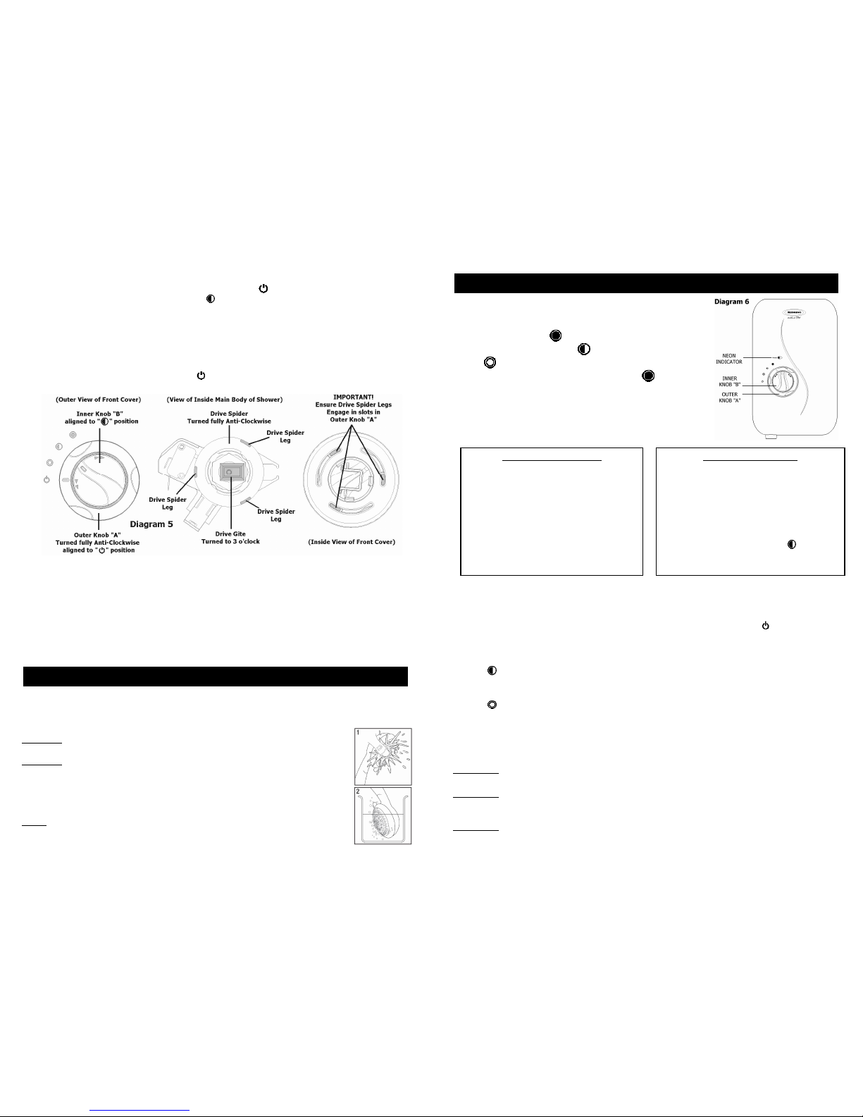
5. Re-Fit the front cover (see Diagram 5),
a. Ensure outer knob “A” is aligned fully anti-clockwise to the “ (stop)” position.
b. Ensure inner knob“B” is aligned fully to the “ (medium)” position.
c. Inthe main body ofthe shower, turn the “Drive Spider” fully anti-clockwise until it stops.
d. Inthe main body ofthe shower, turn the “Drive Gite” until it isat “3 o’clock”.
e. Fit the front cover of the shower to the main bodyensuring thatthe 3 x “Drive Spider Legs” engage
with the slots in outer knob “A”.
f. Check that inner knob “A” has been correctly aligned by ensuring thatthe knob can turn approximately
3/4 of a turn (270°).
g. Check that outer knob “B” has been correctly alignedby ensuring thatall 3 power settings canbe
selected, and the knob “B” returns to the “ (stop)” position.
h. Secure by replacing the top and bottom fasteningscrews.
6. Fit theshower hose, andoperate the shower first without the handset to flush out particles,
fit the handset and then operate the shower ason page 7 or 12 andcheck:
a. That the water gets to a satisfactory temperature.
b. Water flow can be adjusted by inner controlknob “B”.
c. Power selection operates in all3 positions, giving a changein water temperatureand thatthe neon
light functions correctly.
d. Checkagain for leaks
e. That the holes in the shower handset are not blocked
7. DEMONSTRATE OPERATION TOUSER
It is recommended that the shower unit and hose etc. be cleaned usinga soft cloth and that theuseof
abrasive or solventbased cleaning fluid be avoided, especially on any platedfinishes.
We recommend that beforeanycleaning, the isolating switch beturned off, thus avoiding accidentally
switching onthe shower.
WARNING: YOUMUST REGULARLYINSPECT THE SHOWERHOSEFORWEARANDDAMAGE.
REPLACEIFNECESSARY, OREVERYTWOYEARS,WITH OUR APPROVEDPART.
WARNING: IN ORDERTO MAINTAIN THE PERFORMANCE OF YOURSHOWER,
YOUMUST CLEAN THE SHOWERHANDSET REGULARLY
Allwater contains particles of lime-
scale, whichbuild up in the shower handset and
unit reducing the performance.
It is therefore important to clean the shower handset bysimplyrubbing the rubber
nozzles, or soaking in a proprietary lime-scale removerand rinsing thoroughly before use.
NOTE: After use it is normal for somewater to drip from theshower handset for a
few moments. This inhibits scale build-up over prolonged use.
7
IFWATER IS TOO COLD
Turn inner knob “B” clockwise in the
direction of the “red arrows” to “1o’clock”
and continue turning clockwise until youget
the water temperature of your liking.
Wait 20 seconds after each adjustment for
the water temperature tostabilise.
If after turning fully clockwise water is still too
cold, set shower pattern on shower handset
to outer or inner pattern only.
IF WATER IS TOO HOT
Turn inner knob “B” anti-clockwise in the
directionof the “blue arrows” to “11 o’clock”
and continue turning anti-clockwise until you
get the water temperature of your liking.
Wait 20 seconds after eachadjustmentfor
the water temperature to stabilise.
If after turning fully anti-clockwise, water is still
too hot, adjust outer knob “A” to “ (medium)”
setting and re-adjust asabove.
Water flow will be reduced on this setting.
1. Ensure the electricity and water are turned on to the unit.
2. Your shower has 3 power settings selected byturning outer
knob “A” (see Diagram 6).
The most popular is “ (high)”.
There are also options for a “ (medium)”
or “ (cold)”shower (see notes 8and 9).
Forthis example turn outer knob “A”to “ (high) ”
and set inner knob “B” to “12 o’clock”.
3. The water will flow and the neonlight will glow brightly.
4. Allowabout 20 seconds for the temperature of the water
to stabilise. Itis recommended that you do not whollyenter the
water spray during this period, especially if the shower has just been used.
5. Once a temperature settingto yourliking has been achieved, inner knob “B” will rarely need
adjusting. You must however take intoaccount required adjustments for variationsof incoming
mains water temperature between summer and winter (see“Effect of Seasonal Incoming Water
Temperature Changes” page 10).
6. When you have finished showering, turn outer knob “A” anti-clockwise tothe “ (stop)” position.
Water will continue to flow for approximately 7 seconds before switching off.
This reduces the temperature of the water inthe tankfor the next user.
Wait forthe water tostop, and then switchoff the electricity at the ceiling switch or local isolator.
7. The “ (medium)” setting of outer knob “A” reduces the power used by the shower giving a cooler
shower or the option of reducedwater flow.
This optionis mainly for summer usage and if this is usedthen inner knob “B” must be re-adjusted.
8. The “ (cold)” setting of outer knob “A” willsupplywater without anyheating,and the neon light
will goout.
9. Your shower is designed to stabilise temperature changes caused by water pressure fluctuations
(see “Effect of Other Water Devices on Incoming Water Supply” page 10).
10. Note that inner knob “B” IS NOTATAP anddoes notturn the water off.
WARNING: DO NOTSWITCH THE SHOWER ON IFYOU SUSPECT IT OFBEING FROZEN.
WAIT UNTIL YOU ARE SURE IT HAS THAWED OUT.
WARNING: DO NOTOPERATETHE SHOWER IFWATER ISDISCHARGED FROMTHE
PRESSURE RELIEF VALVE. MAINTENANCE IS REQUIREDBEFORE THE SHOWER
CAN BE SAFELY USED.
WARNING: CONSIDERATION SHOULD BEGIVEN TO SUPERVISING THEYOUNG, ELDERLY
AND THE INFIRM WHILSTTHEY USETHIS SHOWER.
HOW TOUSE YOUR ACTIVE 350S SHOWER (DETAILED)

Other manuals for Active 350S

1

Other RED-RING Plumbing Product manuals

RED-RING 600 User manual

RED-RING

RED-RING 600 User manual

RED-RING Selectronic User manual

RED-RING

RED-RING Selectronic User manual

RED-RING Expressions 500S User manual

RED-RING

RED-RING Expressions 500S User manual

RED-RING Expressions 500S User manual

RED-RING

RED-RING Expressions 500S User manual

RED-RING Selectronic Mixer Shower TMV3 User manual

RED-RING

RED-RING Selectronic Mixer Shower TMV3 User manual

RED-RING EXPRESSIONS 550S User manual

RED-RING

RED-RING EXPRESSIONS 550S User manual

RED-RING Xpressions Premier User manual

RED-RING

RED-RING Xpressions Premier User manual

RED-RING Active 320S User manual

RED-RING

RED-RING Active 320S User manual

RED-RING Active 350S User manual

RED-RING

RED-RING Active 350S User manual

RED-RING 650 User manual

RED-RING

RED-RING 650 User manual

RED-RING EXPRESSIONS 570 User manual

RED-RING

RED-RING EXPRESSIONS 570 User manual

RED-RING Active User manual

RED-RING

RED-RING Active User manual

RED-RING Vital RVLS7 User manual

RED-RING

RED-RING Vital RVLS7 User manual

RED-RING Active 3205 User manual

RED-RING

RED-RING Active 3205 User manual

RED-RING PURE 8.5kW User manual

RED-RING

RED-RING PURE 8.5kW User manual

RED-RING Selectronic Premier User manual

RED-RING

RED-RING Selectronic Premier User manual

RED-RING R6508 User manual

RED-RING

RED-RING R6508 User manual

RED-RING Expressions 520M/520TS User manual

RED-RING

RED-RING Expressions 520M/520TS User manual

RED-RING XPRESSIONS User manual

RED-RING

RED-RING XPRESSIONS User manual

RED-RING Xpressions eco-t User manual

RED-RING

RED-RING Xpressions eco-t User manual

Popular Plumbing Product manuals by other brands

Wasserwerk WT14 manual

Wasserwerk

Wasserwerk WT14 manual

JADO IQ 832 701 Series installation instructions

JADO

JADO IQ 832 701 Series installation instructions

Kallista P24412 installation guide

Kallista

Kallista P24412 installation guide

Grohe 96016000 Service manual

Grohe

Grohe 96016000 Service manual

Glacier bay 67568-1027H2 Installation and care guide

Glacier bay

Glacier bay 67568-1027H2 Installation and care guide

CDA TC26 quick start guide

CDA

CDA TC26 quick start guide

Sanela SLU 02TB Mounting instructions

Sanela

Sanela SLU 02TB Mounting instructions

KWC PROTRONIC-S AQUA134 Installation and operating instructions

KWC

KWC PROTRONIC-S AQUA134 Installation and operating instructions

IMI STAP manual

IMI

IMI STAP manual

Felton RW installation guide

Felton

Felton RW installation guide

Hans Grohe Zebris 110 CoolStart 72570 Series Instructions for use/assembly instructions

Hans Grohe

Hans Grohe Zebris 110 CoolStart 72570 Series Instructions for use/assembly instructions

Kohler C3-150 Homeowner's guide

Kohler

Kohler C3-150 Homeowner's guide

Moen Alto T6107 Specifications

Moen

Moen Alto T6107 Specifications

newform NIO 67696E instructions

newform

newform NIO 67696E instructions

Glacier bay GBSH114 instruction manual

Glacier bay

Glacier bay GBSH114 instruction manual

Häfele TAP HT21-CH1P287 instruction manual

Häfele

Häfele TAP HT21-CH1P287 instruction manual

BATHSELECT BS-BNS10 manual

BATHSELECT

BATHSELECT BS-BNS10 manual

Symmons Dia 352SH Series Operation & maintenance manual

Symmons

Symmons Dia 352SH Series Operation & maintenance manual

manuals.online logo
manuals.online logoBrands
  • About & Mission
  • Contact us
  • Privacy Policy
  • Terms and Conditions

Copyright 2025 Manuals.Online. All Rights Reserved.