Omnik Omniksol-5KW-TH-TL3-NS User manual

User Manual
Grid-Connected Inverter
Omniksol-
5KW/6KW-TH-TL3-NS
8KW/10KW/13KW/16KW-TL3-NS

Legal Disclaimer
● Not all or part of this document may be reproduced, stored in a retrieval system, or
transmitted, in any form or by any means, without the prior written permission of our
company.
● The products, services or features you purchased shall be subject to the commercial
contract and terms. All or part of the products, services or features described in this
documentmay not be within the scope of your purchase or use. Unlessotherwise specified
in the contract, no presentation is made or warranty, either express or implied, as to the
contents of this document.
● As standards, specifications, and designs change from time to time, the information in
this document is subject to change without notice. Every attempt has been made to make
this document complete, accurate and up-to-date. Readers are cautioned, however, that
our company reserves the right to make changes without notice. All statements,
information, and recommendations in this document do not constitute a warranty of any
kind, express or implied.

Table of Contents
1 General Information.................................................................................................1
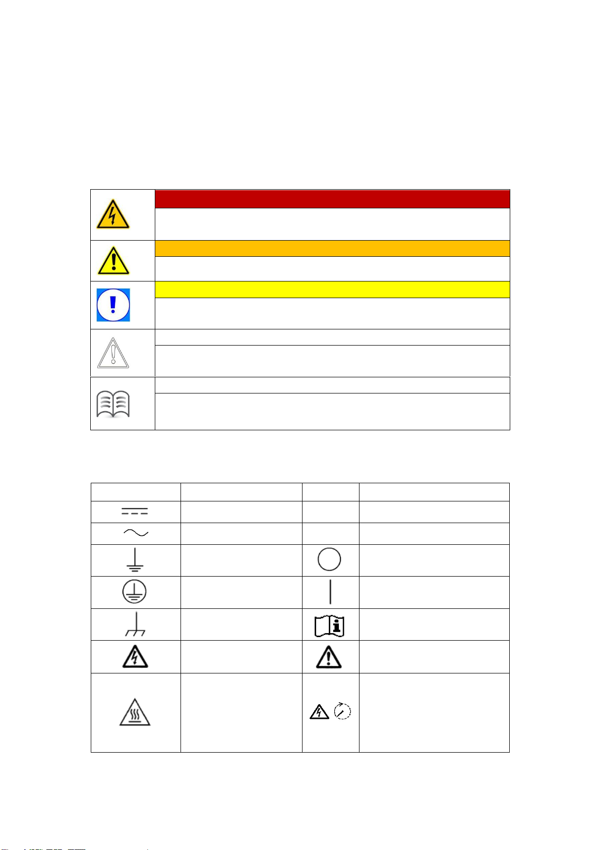
1.1 Safety Messages ............................................................................................................................. 1
1.2 Validity............................................................................................................................................ 2
1.3 Safety Precautions .......................................................................................................................... 2
2 Product Overview....................................................................................................4
2.1 Components of PV Grid-Connected System ................................................................................... 4
2.2 Schematic Diagram......................................................................................................................... 5
2.3 Appearance of Inverter................................................................................................................... 5
2.4 Weights and Dimensions of Inverter .............................................................................................. 6
2.5 Specifications.................................................................................................................................. 6
3 Unpacking and Storage...........................................................................................8
3.1 Unpacking Inspection ..................................................................................................................... 8
3.2 Storage ........................................................................................................................................... 8
4 Installation.............................................................................................................10
4.1 Mounting Location ....................................................................................................................... 10
4.2 Mounting the Inverter.................................................................................................................. 10
5 Electrical Connection.............................................................................................13
5.1 Safety Precautions ........................................................................................................................ 13
5.2 Cable Requirements ..................................................................................................................... 13
5.3 DC Connection.............................................................................................................................. 14
5.4 AC Connection .............................................................................................................................. 15
5.5 Second Protective Earth Connection ............................................................................................ 17
5.7 Connection of Anti-backflow Meter (Optional)............................................................................ 17
6 Installing the Communication Module ....................................................................20
7 Operation ..............................................................................................................22
7.1 Switching On................................................................................................................................. 22
7.2 Switching Off ................................................................................................................................ 22
7.3 LED Indicator Lights ...................................................................................................................... 22
7.4 Auto Test Function(For Italy)................................................................................................... 23
8 Monitoring .............................................................................................................25
8.1 Professional Edition App............................................................................................................... 25
8.2 Home Edition App ........................................................................................................................ 29
9 Troubleshooting for Fault Messages Displayed on APP ........................................32

1
1 General Information
1.1 Safety Messages
Read the manual carefully to become familiar with the equipment before trying to install,
operate, service or maintain it. The following safety messages may appear throughout this
manual or on the equipment to warn of potential hazards.
DANGER
DANGER indicates a hazardous situation which, if not avoided, will result
in death or serious injury.
WARNING
WARNING indicates a hazardous situation which, if not avoided, could
result in death or serious injury.
CAUTION
CAUTION indicates a potentially hazardous situation which, if not avoided,
could result in minor or moderate injury.
NOTICE
NOTICE is used to address practices not related to physical injury, but to
property damage.
NOTE
NOTE is additional information in the manual, which is emphasis and
supplement to the contents and provides prompts that are valuable for the
optimal installation and operation.
This manual and device may also use the following electrical symbols and identification,
shown as follows:
Symbol
Description
Symbol
Description
DC
—
Voltage negative pole
AC
+
Voltage positive pole
Earth (Ground)
Off (Power supply)
Protective Earth
On (Power supply)
Frame or Chassis
Terminal
Refer to the manual
description
Caution, Risk of
Electric Shock
Warning of danger
Caution, Hot Surface
Danger alert of electric
shock. Energy storage timed
discharge
(Time to be indicated
adjacent to the symbol)

2
1.2 Validity
This manual is valid for the following residential three phase on-grid PV inverters
(Hereinafter referred to as inverter):
5kW/6kW/8kW/10kW/13kW/16kW
1.3 Safety Precautions
Follow the precautions and special safety instructions provided in the manual when
operating the products. Our company will not be liable for any consequences that are
caused due to violations regarding general safety regulations and equipment design,
production, and usage safety standards.
Anti-islanding Protection:
Shifting the frequency of the inverter away from nominal conditions in the absence of a
reference frequency (Frequency shift).
Disclaimer
Our company shall not be liable for any consequence caused by any of the following events:
➢Damage caused by transportation
➢Storage conditions that do not meet the requirements specified in this document
➢Incorrect storage, installation, or use
➢Installation or use by unqualified personnel
➢Failure to comply with the operation instructions and safety precautions in this
document
➢Operation in extreme environments which are not specified in this document
➢Operation beyond specified ranges
➢Unauthorized modifications to the product or software code or removal of the
product
➢Device damage due to force majeure (such as lightning, earthquakes, fire, and
storms)
➢Warranty expiration without extension of the warranty service
➢Installation or use in environments which are not specified in related international
standards
DANGER! High voltage may result in death or serious burns!
● Operations on the inverter must be performed by qualified personnel.
● PV arrays exposed to light may generate dangerous voltage.
● Do not touch the electriferous modules in the PV system while the
inverter is running.
● Carefully read the safety precautions in this manual.
DANGER! Do not touch the contacts or terminals connected to the
grid or the equipment, or it may result in electric shock to death or
outbreak of a fire!
● Do not touch the terminals or conductors connected to the grid circuit.
● Read and understand all instructions and safety precautions for grid
connection.
● Follow all the safety precautions for low voltage power grid.

3
DANGER! The damaged device or system fault may result in electric
shock or outbreak of a fire!
● Check if there is damage or other dangerous conditions for the
device before operation.
● Check if the external device and circuit connection are in a safe
state.
● Make sure the device is in a safe state for operating.
WARNING!
● The inverter can be connected to the grid only if it gets permission from
the local electric power department.
● All electrical installations must be made in accordance with national and
local standards and regulations.
WARNING! Operation by non-professional may result in death or
severe burns.
● Only trained electrically qualified persons are permitted to do
electrical operation on this product.
● During maintenance, it is necessary to ensure that at least two staff
members work in the field; the breakers of AC terminal and DC terminal
must be fully disconnected for at least 10 minutes for internal energy
storage components discharging completely, which should be confirmed
with a voltmeter.
NOTICE! Contact or improper operation on printed circuit board or
other electrostatic sensitive components may result in damage to the
components.
● Avoid unnecessary contacts with circuit boards.
● Comply with electrostatic protection standards, wear an antistatic wrist
strap.
➢When installing PV arrays during the day, opaque material should be used to cover
the solar battery arrays, otherwise, the solar array will generate high voltage under
sunlight.
➢The input DC voltage must not exceed 1000 V, and the excessive voltage may result
in damage to the device.
➢The inverter must be properly transported, stored, assembled, installed, operated
and maintained.
➢All operations and wiring must be made by qualified personnel only to ensure that all
electrical installations meet the electrical installation standards. In order to ensure
safe operation, the device should be grounded properly and provided with
necessary short circuit protection.
➢Ensure that DC side and AC side have no electric charge before maintaining or
checking the inverter.
➢The capacitor in the inverter may present a shock hazard even all connections of the
inverter are disconnected. Therefore, the device should be maintained and operated
after turning off the inverter for at least 10 minutes.
➢Follow all the instructions in this manual.
➢The inverter will generate heat during operating, do not touch the radiator and other

4
hot components of the inverter during operating to avoid burns.
2 Product Overview
2.1 Components of PV Grid-Connected System
PV grid-connected system consists of PV modules, PV grid-connected inverters, metering
device and power distribution system. The solar energy is converted into DC via PV
modules, and then the DC is converted into sinusoidal AC which has the same frequency
and phase as the utility grid and fed into the utility grid via inverters.
Components
Description
A PV Modules
Monocrystalline silicon, polycrystalline silicon, and thin-film batteries with Ⅱ
level protection and no need to be grounded
B Inverter
5kW/6kW/8kW/10kW/13kW/16kW
C Electric Meter
Standard measuring tools for inverter output power
D Utility Grid
TT, TN-C, TN-S, TN-C-S

5
2.2 Schematic Diagram
Note: The inverter topology consists of boost and inversion. PV input feeds into the
public power grid via DC filtering, boosting, DC bus decoupling, inverter and AC filtering.
It adopts DSP and MCU dual-chip redundancy technology to realize fault detection
and protection of the inverter. The interior of the inverter has two groups of relays
connected between the inverter circuit output and power grid port, and the groups of
relays have self-test function that can ensure reliable disconnecting of the
connection between the inverter circuit and the utility grid in the event of a failure.
It realizes the remote monitoring of the PV power generation system via the communication
methods of RS485, GPRS and Wi-Fi.
2.3 Appearance of Inverter
No.
Description
Explanation
①
LED Display Panel
To display the inverter running state / communication
status
PV insulation
resistance
detection
LED Bluetooth RS485 RS485 WIFI/GPRS
MASTER MCU SLAVE MCU
Leakage
current
deteciton
DC switch MPPT circuit Grid-connected
relay
L1
L2
L3
N
PE
PV1+
PV1-
PV2+
PV2-

6
②
DC Input Terminals
To connect inverter to PV modules
③
DC Switch
To directly control DC input On / Off
④
Communication
Terminals
To connect Wi-Fi or other communication module
⑤
Ventilation Valve
To prevent from condensing and fogging, and balance
differential pressure between inside and outside the
cabinet
⑥
DRM Communication
Interface of demand response modes for Australia grid
dispatching
⑦
AC Output Terminals
To feed the inverter output energy into the grid
⑧
Ammeter
Communication and
Digital Input
Input interface for electric meter communication and
external digital input
⑨
Mounting Bracket
To fix the inverter on the wall mounting bracket
2.4 Weights and Dimensions of Inverter
Inverters
Weight
Dimensions (W×D×H)
5kW/6kW/8kW/10kW/13kW/16kW
25 kg
515 mm × 166.5 mm × 435 mm
Dimensions of 5kW/6kW/8kW/10kW/13kW/16kW inverter:
2.5 Specifications

7
MODEL
OMNIKSOL
-5K-TH-
TL3-NS
OMNIKSOL
-6K-TH-
TL3-NS
OMNIKSOL
-8K- TL3-
NS
OMNIKSOL
-10K- TL3-
NS
OMNIKSOL
-13K -TL3-
NS
OMNIKSOL
-16K -TL3-
NS
INPUT(DC)
Max. Input Power
6.5kW
7.8kW
10.4kW
13kW
16.9kW
20.8kW
Max. Input Voltage
1000V
Start-up Voltage
180V
250V
MPPT Voltage Range
120-950V
200-950V
MPPT Voltage Range at Full Load
250-850V
280-850V
380-850V
470-850V
410-850V
500-850V
Max. Input Current
11A/11A
11×2A/11A
Max. Short Circuit Current
12A/12A
12×2A/12A
Number of MPPTs
2
Number of DC Inputs
A:1/B:1
A:2/B:1
OUTPUT(AC)
Rated Output Power
5kW
6kW
8kW
10kW
13kW
16kW
Max. Active Power
5kW
6kW
8kW
10kW
13kW
16kW
Max. Apparent Power
5kVA
6KVA
8kVA
10kVA
13kVA
16kVA
Max. Output Current
7.3A
8.7A
11.6A
14.5A
18.9A
23.2A
Rated Grid Voltage
230/400V,3W+N+PE
Grid Voltage Range
176-276V/304-480V
Rated Grid Frequency
50/60Hz
Gird Frequency Range
45-55/55-65Hz
THD
<3%(rated power)
Output Current DC Component
<0.5%In
Power Factor
>0.99(rated power)
Power Factor Adjustable
0.8 leading~0.8 lagging
EFFICIENCY
Max. Efficiency
98.65%
European Efficiency
98.2%
PROTECTION
DC Switch
Available
DC Reverse Polarity Protection
Available
Ground Insulation Resistance
Detection
Available
Leakage Current Protection
Available
Output Overcurrent Protection
Available
Output Overvoltage Protection
Available
Anti- islanding Protection
Available
DC Surge Protection
Class III lightning protection
AC Surge Protection
Class III lightning protection
PID Protection and Repair
Optional
OTHERS
Display
LED, Bluetooth (Optional)

8
Communication
RS485, Wi-Fi(optional), GPRS (optional)
Safety Standard
NB/T 32004, IEC62109-1, IEC62109-2
EMC Standard
NB/T 32004, EN 61000-6-1, EN 61000-6-2, EN 61000-6-3, EN 61000-6-4
Self-consumption at Night
<1W
Isolation
Transformerless
IP Rating
IP65
Operating Temperature
-25℃+ 60℃(> 45℃ downgrading)
Relative Humidity
0~100% (no condensation)
Cooling
Natural cooling
Altitude
4000m > (2000m downgrading)
Dimensions (W*D*H) [mm]
515*166.5*435
Weight [kg]
25
Note: The above specifications are for reference only, please prevail in kind in the
event of any inconsistency.
3 Unpacking and Storage
3.1 Unpacking Inspection
Although the product has been rigorously tested and inspected before delivery, damage
may still occur during transport. Check that the delivery is complete, check the packaging
and the inverter for externally visible damage, and inspect the package contents upon
receipt. Notify the carrier and dealer If any damage is found or any component is missing.
Scope of delivery:
No.
Designation
Quantity
1
Grid-Connected PV Inverter
1 pcs
2
User Manual
1 pcs
3
Quick Guide
1 pcs
4
PV input Terminal
3 sets
5
AC output Terminal
1 set
6
Communication Module (Wi-Fi)
1 set
7
Expansion Screws
3 sets
8
Hexagon Socket Screws with Spring and Plain
Washer
1 pcs
9
Outer Hex-cross Screw with Spring and Plain Washer
1 pcs
10
Wall Mounting Bracket
1 pcs
11
Waterproof Terminal
2 set
3.2 Storage
If the inverter is not immediately put into operation, it needs to be stored in a specific
environment:
➢The inverter needs to be repackaged with the original packaging and the desiccant is

9
retained. The packaging box needs to be sealed with tape.
➢The inverter should be stored in a clean and dry place that free from dust and water
vapor erosion.
➢The temperature of the storage place should be kept at -30°C - +85°C and the relative
humidity should be maintained between 0 and 100% without condensation.
➢If the inverter should be stacked, it is recommended that the maximum number of
layers can be accumulated no more than 5 layers.
➢The inverter must avoid the corrosive chemicals, otherwise it may be corroded.
➢It needs regular inspection during the storage, and the packaging materials should be
replaced timely in the case of damage by rats and vermin.
➢Do not tilt or invert the packaging box.
➢After long-term storage, the inverter can’t be put into operation until the
comprehensive inspection and testing is made by qualified personnel.

10
4 Installation
4.1 Mounting Location
DANGER! Danger to life due to fire or explosion!
● Do not mount the inverter on flammable construction
materials.
● Do not install the inverter in areas where highly
flammable materials are stored.
● Do not install the inverter in areas with a risk of
explosion.
In order to ensure that the inverter operates properly, the installation environment and
requirements are as follows:
➢The inverter is intended for outdoor use with IP 65 rating. The installation location
should be cool and ingood ventilation.Do not exposethe inverter in the direct sunlight,
otherwise, it may result in excessive temperature rise inside the inverter, downgrading
operation of protection circuit and even shutdown due to over-temperature fault.
➢Rain and snow do impact on the service life of the inverter, do not install the inverter
in the rain and snow or do some appropriate shelter.
➢The inverter adopts natural cooling, the ventilation and cooling are very important. Do
not install the inverter in a closed enclosure, otherwise the inverter should be too hot
to operate or even damaged.
➢The inverter should be installed in the reinforced concrete wall or metal wall that can
bear the weight of the inverter. The inverter must be installed vertically. Ensure that
the installation place does not shaking.
➢The inverter operation will generate some noise (< 40 dB), it should be installed away
from the residential areas. Ensure that the installation location is convenient for
viewing LED lights and LCD display screen. Sufficient clearances around the inverter
must be reserved for ventilation, cooling, installation, maintenance and safe access.
➢Do not install the inverter outdoors in salt areas because it will be corroded there and
may cause fire. A salt area refers to the region within 500 meters from the coast or
prone to sea breeze. The regions prone to sea breeze vary depending on weather
conditions (such as typhoons and monsoons) or terrains (such as dams and hills).
CAUTION
Ambient temperature range shall be -25°C to +60°C. It will affect the
inverter output power when the temperature exceeds the limit.
Environmental relative humidity must be in the range of 0% ~ 100%.
4.2 Mounting the Inverter
4.2.1 Clearance

11
Note: Only install the inverter vertically or tilted backwards no more than 15 degrees. Do
not tilt or install the inverter horizontally. The wiring terminal should be downwards.
In order to maintain sufficient ventilation, when installing the inverter, a minimum
clearance of 30 cm at the sides and 50 cm at the top must be maintained. Operation and
reading are made easier by installing the inverter with its display at eye level and by
keeping a distance of 100 cm from the front. All cables are routed to the outside through
the underside of the enclosure. Therefore a minimum clearance of 50 cm must be
observed here.
4.2.2 Installation Procedure
1. Place the wall mounting bracket against a suitable wall for mounting and align using a
level. Mark the position of the drill holes using the wall mounting bracket.
2. Drill holes on the markings for them.
3. Secure the wall mounting bracket to the wall using expansion screws. Tighten the
screws with a minimum torque of 30Nm, and M6 x 50 expansion bolts are
recommended for use.

12
4. Attach the inverter to the wallmounting bracket. Screw the inverter to the wall mounting
bracket on both sides using the M5 screws provided. Tighten the screws and make
sure that they are securely in place.
5. The Wall mounting bracket reserved a padlock hole to prevent the inverter from being
stolen. The anti-theft lock needs to be prepared by the user himself.

13
5 Electrical Connection
5.1 Safety Precautions
DANGER!
Improper wiring may result in fatal injury to operator or unrecoverable
damage to the inverter. Only qualified personnel can perform the
wiring operation. The breakers on the AC/DC sides of the inverter
must be disconnected and the warning marks must be set before
wiring.
WARNING!
The voltage and current parameters of the inverter must be
considered when designing the PV system (see 2.5).
WARNING!
Ensure that the electrical connection design is in compliance with the
local national and local standards.
CAUTION
The IP rating of this inverter is IP 65, please use the wiring terminal
provided, otherwise the IP rating of the inverter may be reduced.
CAUTION
All cables must be connected firmly and reliably, properly insulated
and avoid to be damaged easily.
CAUTION
The inverter can only be connected to the utility grid after getting the
approval from the local electric power department.
5.2 Cable Requirements
Cable
Cable size (mm²)
PV Array DC+/DC-
Provide 6 inputs, cable diameter > 4mm2
Power Grid L1 Phase
Provide single output, cable diameter > 6 mm2
Power Grid L2 Phase
Provide single output, cable diameter > 6 mm2
Power Grid L3 Phase
Provide single output, cable diameter > 6 mm2
Power Grid N
Cable diameter > 6 mm2
Ground Wire
Cable diameter > 6 mm2
Connecting the product to the electrical utility grid should be approved by
the local electricity service department, and the connection and operation
must be made only by qualified personnel.

14
5.3 DC Connection
DANGER!
Before electrical connection, cover the PV battery modules with light-
proof material and disconnect the circuit breaker on the DC side.
WARNING!
This product is a non-isolated inverter, the positive and negative
electrodes of the PV module cannot be grounded, otherwise it will emit
PV ISO Fault. The inverter cannot operate normally even be damaged.
CAUTION
When designing PV arrays, the open-circuit voltage of each PV string
less than 1000 V must be considered, and the maximum allowable
short-circuit current for each PV string is no more than 12 A.
NOTE
All models of inverters are featured with two MPPT inputs and two
groups of input terminals, and two groups of PV strings can be
connected to the DC side.
DC connection terminals are included in scope of delivery. Please connect the DC cables
selected based on the above requirements to the connector by following the steps below.
(Note: During connecting, use the same color for the positive cables with a mark and use
another same color for negative cables with a mark. For example, generally red cables are
used for the positive terminal and black cable are used for the negative.)
Positive (+) Input Terminal and Die
Negative (-) Input Terminal and Die
Wiring on the DC side

15
1. Strip the DC cable insulation about 8 mm to expose the copper wire. Insert the cable
copper wire into themetal core of the connector and tighten it with a crimper (As shown
in the figure below).
2. Loosen the terminal cover and pass the cable through the terminal cover. Insert the
die into the wiring slot till you hear a sound indicating that the connection is in place.
Tighten the terminal cover (As shown in the figure below).
3. Check whether the PV arraycable connection polarity is correct with a voltmeter whose
DC voltage measurement range is over 1000 V, and verify that the open-circuit voltage
does not exceed the specification. When the ambient temperature is above 10°C, the
open-circuit voltage of PV arrays can’t exceed 90% of the maximum DC voltage of the
inverter. Otherwise, at the low temperatures, the voltage of PV arrays may exceed the
maximum input voltage of the inverter and cause damage to the inverter.
4. Disconnect the circuit breaker on the DC side and connect the PV input cable to the
inverter separately.
5.4 AC Connection
WARNING!
Ensure that electrical connections are in compliance with the local
national and local standards.
WARNING!
The uncharged metal parts in PV power generation systems consist of PV
module bracket, the metal case of the inverter, which should be grounded
reliably. The grounding pole should meet the standard requirements.
The grounding parts of multiple inverters and PV arrays should be
connected to the same grounding bus, building a reliable equipotential
connection.
CAUTION
According to the requirement of EN50178, the right side of the inverter
has a second earth terminal, which can be connected by the combination
screws M4 × 8 with flat pad and spring pad.
Wiring on the AC side
1. Pass the appropriate length of cable through the waterproof connector cap and shell.
Only apply to multistrand copper wire, length of the earth wire should be 5 mm longer
than the live wire and zero wire. Strip the cable insulation about 7 mm (As shown in
the figure below).

16
2. Fix L1, L2, L3, N and PE wires to the corresponding AC terminals with a screwdriver
and ensure that the PE wire is properly grounded (As shown in the figure below).
3. Insert the shell into the AC terminal, hear a sound of “click”, then tighten the
waterproof connector cap.
4. Push the locker onto the socket housing completely, then rotate the locker according
to the direction instructed by the marks on the lock.

17
CAUTION
Making the inverter output cable and installation instructions is only for
reference. Please note that OMNIKSOL-5~16K-TH-TL3-NS output
wiring is 3W + N + PE.
5.5 Second Protective Earth Connection
DANGER!
Do not connect the neutral wire to the enclosure as a PE cable.
Otherwise, electric shocks could occur.
CAUTION
The PE point at the AC output port is used only as a PE equipotential
point, and cannot substitute for the PE point on the enclosure.
There is a protective grounding hole at the bottom of the inverter. The user must make the
inverter grounded through the grounding hole and tighten it with M4*8 screws (As shown
in the figure below).
5.7 Connection of Anti-Backflow Meter (Optional)
The inverter equipped with anti-backflow function can perform power regulation and
prevent feeding energy into the grid. Before using the anti-backflow function, the user
should read the instructions carefully and correctly connect the cables as shown in the
figure. Connection error may lead to unpredictable consequences, contact the
maintenance personnel in this case.
This manual suits for next models
5
Table of contents
Other Omnik Inverter manuals

Omnik
Omnik Omniksol-3k-TL User manual

Omnik
Omnik Omniksol-10k-TL3 User manual

Omnik
Omnik SMP300 User manual

Omnik
Omnik Omnikhyd Inverter 3KW User manual

Omnik
Omnik NS Series User manual

Omnik
Omnik Omniksol-2.5k-TL2-S User manual

Omnik
Omnik Omniksol-3k-TL2 User manual

Omnik
Omnik Omniksol-2k-TL3-S User manual

Omnik
Omnik Omniksol-1k-TL-M User manual

Omnik
Omnik Omniksol-1k-TL User manual