WFCO WF-5200 Series User manual

OPERATOR’S MANUAL
WF-5200 SERIES PURE SINE WAVE INVERTER
WF-5220
ARTERRA DISTRIBUTION
(877) 294-8997
wfcoelectronics.com
WARRANTY
Fax (574) 294-8698
Distributed by Arterra in the U.S.A. and Canada

2
SAFETY INFORMATION ...................................................................................................... 1
GENERAL INFORMATION
General Safety Precautions.................................................................................................... 1
Precautions When Working with Batteries........................................................................... 1
Installation................................................................................................................................ 2
FUNCTIONAL CHARACTERISTICS
General Information................................................................................................................ 2
Application............................................................................................................................... 3
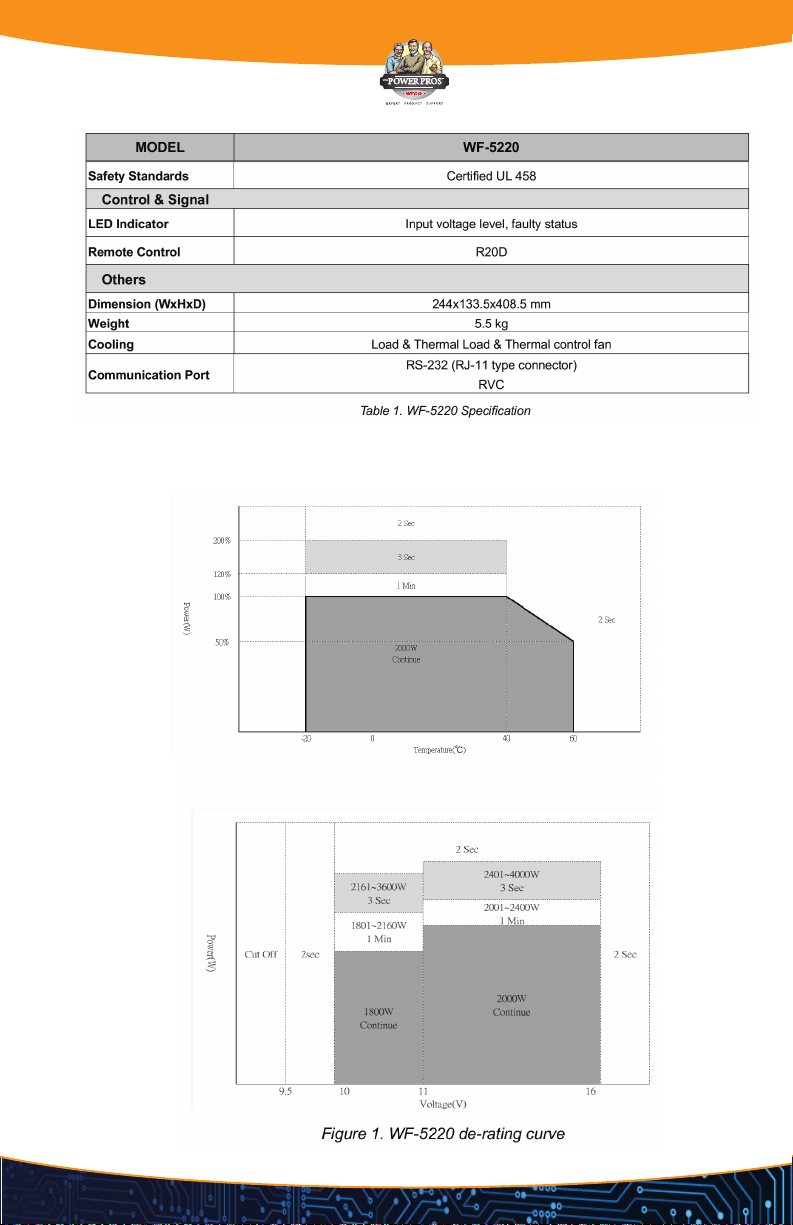
Electrical Performance.........................................................................................................4-5
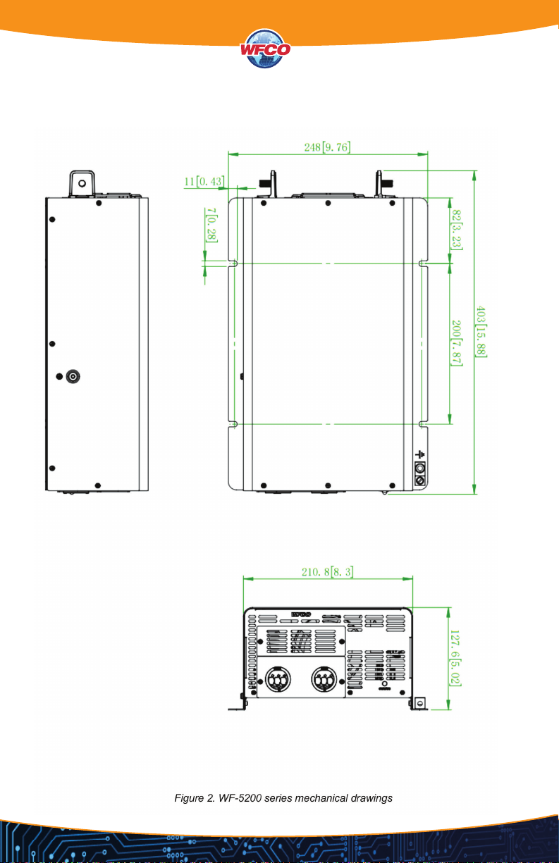
Mechanical Drawings.............................................................................................................. 6
INTRODUCTION
Power ON / OFF / REMOTE (Main) Switch.......................................................................... 7
AC Output ............................................................................................................................... 8
AC Output Socket................................................................................................................... 8
AC Input Circuit Breaker......................................................................................................... 8
LED Indicator........................................................................................................................... 8
DC Input - / DC Input +.......................................................................................................... 8
RVC BUS portDC..................................................................................................................... 8
Terminal Resistor ..................................................................................................................... 9
LCM Port ................................................................................................................................ 10
Protections Features............................................................................................................. 14
DC WIRING CONNECTIONS
DC Input Terminals .............................................................................................................. 15
Hard-wire Installation............................................................................................................ 16
WARRANTY INFORMATION............................................................................................... 20
TABLE OF CONTENTS
LEGAL PROVISIONS
Copyrights 2017 WFCO Electronic IND. CO. All Rights Reserved.
Any part of this document may not be reproduced in any form for any purpose without the prior written permission of WFCO
Electronic IND. CO. For the conditions of the permission to use this manual for publication, contact WFCO Electronic IND.
CO., LTD. In all related WFCO product activities, Neither WFCO Electronic IND. CO., LTD. nor its distributors or dealers be
liable to anyone for indirect, incidental, or consequential damages under any circumstances. Specications are subject to
change without notice. Every attempt has been made to make this document complete, accurate and up-to-date. WFCO
Electronic IND. CO., LTD reserve the right to make changes without notice and shall not be responsible for any damages,
including indirect, incidental or consequential damages, caused by reliance on the material presented, including, but not
limited to, omissions, typographical errors, arithmetical errors or listing errors in the content material. All trademarks are
recognized even if these are not marked separately. Missing designations do not mean that a product or brand is not a
registered trademark.

1
SAFETY INFORMATION
WF-5200-AD Series Pure Sine Wave Inverter
• Do not expose the Inverter to rain, snow, spray, bilge or dust. To reduce risk of hazard, do not
cover or obstruct the ventilation openings. Do not install the inverter in a zero-clearance
compartment. Overheating may take place.
• To avoid a risk of re and electric shock, please make sure that existing wiring is in good
electrical condition; and that wire size is not undersized. Do not operate the Inverter with
damaged or substandard wiring.
• This equipment contains components which can produce arcs or sparks.
• To prevent re or explosion do not install in compartments containing batteries or ammable
materials or in locations which require ignition protected equipment. This includes any
space containing gasoline-powered machinery, fuel tanks, joints, ttings, or other connection
between components of the fuel system.
• An over current protection at the time of installation shall be provided by others for the AC
output circuit.
• Additional breakers suitable for 20 A branch circuit protection shall be provided for the
GFCI receptacles.
PRECAUTIONS WHEN WORKING WITH BATTERIES
• If battery acid contacts skin or clothing, wash immediately with soap and water. If acid enters
eye, immediately wash eyes with running cold water for at least 20 minutes and get medical
attention immediately.
• Never smoke or allow a spark or ame in vicinity of battery or engine.
• Do not drop a metal tool on the battery. The resulting spark or short-circuit on the battery or
other electrical part may cause an explosion.
• Remove personal metal items such as rings, bracelets, necklaces and watches when working
with a lead-acid battery. A lead-acid battery produces a short-circuit current high enough to
weld a ring or similar item to metal causing a severe burn.

2
INSTALLATION
The power inverter should be installed in a location that meets the following requirements:
• Dry – Do not allow water to drip or splash on the inverter.
• Cool – Ambient air temperature should be between -20°C and 50°C, but the cooler the better.
• Safety – Do not install batteries in the compartment or other areas near ammable fumes such
as fuel storage areas or engine compartments.
• Ventilated – Allow at least one feet of clearance around the Inverter for air ow. Ensure the
ventilation shafts on the rear and bottom of the unit are not obstructed.
• Dust-free – Do not install the Inverter in dusty environments here dust, wood particles or
other lings/shavings are present. The dust can be pulled into the unit when the cooling fan is
in operation.
• Close to batteries – Avoid excessive cable lengths but do not install the inverter in the same
compartment as batteries.
• Use the recommended wire lengths and sizes (refer to section 4.DC wiring connections).
• Do not mount the inverter where it is exposed to the gases produced by the battery. These
gases are very corrosive and prolonged exposure will damage the inverter.
Shock Hazard. Before proceeding further, carefully check that the inverter is NOT connected to
any batteries, and that all wiring is disconnected from any electrical sources. Do not connect the
output terminals of the inverter to an incoming AC source.
FUNCTIONAL CHARACTERISTICS
WF-5200-AD Series Pure Sine Wave Inverter
GENERAL INFORMATION
WF-5200 series is new generation power inverter equipped with AC transfer switch. WF-5200
series is suitable for RV, Marine and Emergency appliances.
Features
• User-friendly remote control
• RS-232 & RVC communication
• Input & output fully isolation
• UVP & OVP is selectable by remote control (R20D)
• Input Protection: Reverse Polarity (Automatic) / Battery Under Voltage / Battery Over Voltage /
Grid Under Voltage / Grid Over Voltage Protection
• Output Protection: Short Circuit / Overload / Over Temperature Protection
To get the most out of the power inverter, it must be installed and used properly. Please read the
instructions in this manual before installation and operation of this model.

3
APPLICATION
• Power tools–circular saws, drills, grinders, sanders, buffers, weed and hedge trimmers,
air compressors.
• Ofce equipment – computers, printers, monitors, facsimile machines, scanners.
• Household items – vacuum cleaners, fans, uorescent and incandescent lights, shavers,
sewing machines.
• Kitchen appliances – coffee makers, blenders, ice markers, toasters.
• Industrial equipment – metal halide lamp, high pressure sodium lamp.
• Home entertainment electronics – television, VCRs, video games, stereos, musical instruments,
satellite equipment.
• Vehicle, yacht and off-grid power systems.

4
ELECTRICAL PERFORMANCE
WF-5220 Specication

5
DE-RATING CURVE

6
MECHANICAL DRAWINGS

7
POWER ON / OFF / REMOTE (MAIN) SWITCH
• Please make sure the inverter turns off before installation.
• The input comes from AC Grid can’t be controlled by switch. Please disconnect the AC Grid
when you operate the main inverter unit in order to avoid the electric shock.
AC Output (Please refer to hard wiring installation)
AC output socket (please refer to 4-2)
AC INPUT CIRCUIT BREAKER - The AC input circuit breaker protects the model from overload.
When an overload condition exists, the circuit breaker stops supplying output AC grid power.
The breaker will recover automatically.
CHASSIS GROUND: CONNECT THE WIRE # 8 AWG TO VEHICLE CHASSIS
Operating the inverter without a proper ground connection may cause electrical safety hazard.
INTRODUCTIONS

8
LED INDICATOR
DC INPUT - / DC INPUT +
Please refer to DC wiring connections.
RVC BUS portDC
LCM port is for remote control connection only. Please make sure the connection is correct. (CAN
cable to CAN1 / CAN2 port , Remote cable to LCM port) If CAN cable is connected to LCM port,
or vice versa, the inverter will be damaged.

9
NOTE: The cables should be as short as possible (less than 32.8 feet / 10 meters) so that they
can handle the signal.
TERMINAL RESISTOR
LCM PORT
Connection for LCD remote control panel, you can set
and display the WF-5200 series operation status.

10
LCM PORT
Connection for LCD remote control panel, you can set
and display the WF-5200 series operation status.
THE R20DIS EQUIPPED WITH THE FOLLOWING FEATURES:
LED Indicator - The LED provides the inverter status in a straightforward way.
LCD Display - The LCD display is a 16 x 2 line alphanumeric display used for setting up the
inverter/charger operation, as well as, viewing current status or fault messages.
ON/OFF Pushbutton - To turn on/off UNIT quickly
Four Buttons - Click buttons allows you to select a menu item or to save a setting, once it is
displayed on the LCD screen.
Turning the unit OFF does not mean to disconnect the batteries or AC Power Source. Therefore
the “AC output load” is still active. Only use the remote control cable supplied, using different
cables could cause permanent damage to the inverter unit

11
INSTALLATION GUIDELINES
• Please determine the remote cable route throughout the home or vehicle/boat, both to and
from the inverter before connecting any wires.
• Always check for existing electrical, plumbing, or other areas of potential damage before
drilling or cutting into walls to mount the remote.
• Make sure all wires have a smooth bend radius and do not become kinked.
• Please ensure the conductors passing through walls, bulkheads, or other structural members
are protected. This minimizes insulation damage such as chang, which can be caused by
vibration or constant rubbing when installing this remote in a boat, RV, or truck.
INSTALLATION OVERVIEW
The remote is required in order to connect the inverter. Each inverter must be connected directly
to the remote using the supplied RJ11 communication cables. The remote must be located close
to the inverters within nine meters and acts as the system control panel.
MOUNTING THE INVERTER
• Select an appropriate location to install the remote.
• Mount the remote base to the wall using the four screws provided.
CONNECTING THE RJ-11 CABLE
Please use RJ-11 cable supplied with remote to connect to inverter. See below indication.

12
FRONT PANEL

13
R20D MENU MAPS
UNI Treadings
Setup
UNIT LED Indicator

14
PROTECTION FEATURES
Connect the cables to the power input terminals on the front panel of the inverter. The red
terminal is positive (+) and black terminal is negative (-). Insert the cables into the terminals and
tighten the screw to clamp the wires securely.
• Make sure all the DC connections are tight (torque to 11 ft-lbs, 15 Nm Max.). Loose
connections could overheat and result in a potential hazard.
• The installation of a fuse must be on the positive cable. Failure to place a fuse on “+” cables
running between the inverter and battery may cause damage to the inverter and will
void warranty.
• Also, only use high quality copper wire and keep the cable length short - maximum of
three - six feet.
DC WIRING CONNECTIONS

15
Do not place anything between battery cable
lug and terminal surface. Assemble exactly as shown.
During the rst installation, a small spark is a normal phenomenon because the internal
capacitors charging. Do not be concerned.
DC INPUT TERMINALS
Connect DC input terminals to 12V / 24V / 48V battery or other power sources. [ + ] represents
positive, [ - ] represents negative. Reverse polarity connection can blow the internal fuse and may
damage the inverter permanently.

16
HARD-WIRE INSTALLATION
WF-5200 series provides the exibility of hard-wire connection and this function will make
external control panel wiring easier.
GENERAL MODEL
Step 1 - Remove the four screws of AC wiring compartment and pull it out with care.
Step 2 - Pull the line through the snap bushing of the AC wiring compartment cover, then follow
below picture operation.

17
100VAC~120VAC AC System
Connect AC output and AC input wiring to the WF-5200 series terminals.
Please take the following information as your reference.

18
NEUTRAL GROUNDING CONNECTION SETTING (FOR WF-5220 ONLY)
The default setting is option A: NO CONNECTION BETWEEN NEUTRAL CONDUCTOR (N) OF
THE AC OUTPUT AND SAFETY GROUND (PE/GND)
GFCI CONNECTOR
Recommend GFCI connector:
• HUBBELL INC WIRING DEVICE DIV, Type GFRST20W. Rated 125V, 20A
• LEVITON MFG CO INC, Type GFWR2 Rated 125V, 20A
• COOPER WIRING DEVICES, Type SGF20. Rated 125V, 20A
• PASS & SEYMOUR INC, Type 2097W,Type 2097TRWR. Rated 125V, 20A
This manual suits for next models
1
Table of contents
Other WFCO Inverter manuals