Redarc DPS1225 User manual

In-vehicle DC Power Supply
DPS1225, DPS1240,
DPS2410 & DPS2420

2
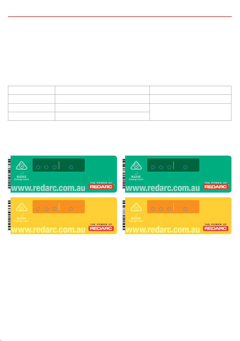
THE DPS1225, DPS1240, DPS2410 & DPS2420
The DPS series In-vehicle DC Power Supplies feature technology designed to supply 12V or 24V
(model dependent) electrical loads such as lamps, radios, small motors, computer and communications
equipment, fridges, pumps and TVs from a 12V or 24V automotive power system.
1 WARNING & SAFETY INSTRUCTIONS
SAVE THESE INSTRUCTIONS - This manual contains IMPORTANT SAFETY INSTRUCTIONS for the
DPS1225/DPS1240/DPS2410/DPS2420 DC Power Supplies.
DO NOT OPERATE THE Power Supply UNLESS YOU HAVE READ AND UNDERSTOOD THIS MANUAL
AND the Power Supply is installed as per these installation instructions.
WARNING
DO NOT USE THE DPS1225/DPS1240/DPS2410/DPS2420 TO CHARGE BATTERIES. DOING SO MAY
RESULT IN HARM TO THE USER AND/OR DAMAGE TO THE DPS1225/DPS1240/DPS2410/DPS2420.
CAUTION
1. This appliance is not intended for use by persons (including children) with reduced physical, sensory
or mental capabilities, or lack of experience and knowledge, unless they are supervised or have been
instructed on how to use the appliance by a person responsible for their safety. Children should be
supervised to ensure that they do not play with the appliance.
2. Do NOT alter or disassemble the Power Supply under any circumstances. All faulty units must be
returned to REDARC for repair. Incorrect handling or reassembly may result in a risk of electric shock
or fire and may void the unit warranty.
3. Check the manufacturers data for your equipment/loads and ensure the maximum voltage of
the DPS1225/DPS1240/DPS2410/DPS2420 does not exceed the manufacturers recommended
maximum operating voltage.
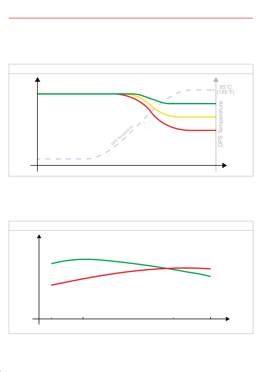
4. The DPS1225/DPS1240/DPS2410/DPS2420 will achieve best results when proper load and vehicle
maintenance is regularly performed.

3
CONTENTS
1 WARNING & SAFETY INSTRUCTIONS 2
2 SPECIFICATIONS 4
3 FUSING 4
4 PRODUCT FUNCTION 5
4.1 Display Panel 5
4.2 Unit Performance Characteristics 6
4.3 Error Codes 7
5 INSTALLATION 7
5.1 RED wire—Input Source Positive 7
5.2 BLUE wire—Ignition Control 8
5.3 ORANGE wire—Output Voltage Select 8
5.4 BROWN wire—Output load Positive 9
5.5 BLACK wire—Common Ground 9
5.6 GREEN wire—Optional External LED 9
5.7 Earth Isolation 9
5.8 Cable sizing 10
5.9 Wiring 10
5.10 Connecting in Parallel 12
6 TROUBLESHOOTING 13
7 WARRANTY 15

4
2 SPECIFICATIONS
Part Number DPS1225 DPS1240 DPS2410 DPS2420
Input Voltage Range 9 to 32V
Recommended Input Fuse*1 40A
(REDARC FK40
recommended)
60A
(REDARC FK60
recommended)
40A
(REDARC FK40
recommended)
60A
(REDARC FK60
recommended)
Nominal Output Current Rating 25A 40A 10A 20A
Surge Current Rating 50A 80A 20A 40A
Recommended Output Fuse*1 40A
(REDARC FK40
recommended)
60A
(REDARC FK60
recommended)
40A
(REDARC FK40
recommended)
40A
(REDARC FK40
recommended)
No Load Current <100mA <200mA
Standby Current <5mA
Output Voltage
(selected with Orange wire)
No Connection 12.0V 24.0V
Earth 13.7V 27.4V
Positive supply 14.5V 29.0V
Line & Load Regulation ±1%
Conversion Efficiency >94%
Operating Temperature –50°C to +50°C (–58°F to +122°F)
Weight 680g (24 oz)
Dimensions 150 × 120 × 37mm (5.9×4.7×1.5")
Standards CE, C-Tick, AS/NZS CISPR1 1:2004
Warranty 2 Years
*1. Please refer to FUSING below.
Voltage tolerance of ±0.12V.
3 FUSING
REDARC recommend using MIDI style bolt down fuses as they
ensure a low resistance connection. The REDARC FK40 and FK60
fuse kits are recommended.
Blade type fuses are not recommended as they can result in a high
resistance connection which causes excess heat and may damage
the fuse holder and/or the wiring. Self-resetting circuit breakers
are not recommended as they may trip prematurely and continue
to cycle until failure, due to the heat generated by the current
flowing through the wires.

5
4 PRODUCT FUNCTION
The DPS1225/DPS1240/DPS2410/DPS2420 is a DC-DC power supply designed to run electrical loads.
The input voltage of the DPS can be above, below or equal to the output voltage making it ideal for
running equipment where specific load voltages or extreme voltage drop are an issue.
The DPS is also designed to isolate the main battery from the load when the vehicle is turned off to avoid
flattening the vehicle’s starter battery.
4.1 Display Panel
The front panel features 4 LEDs to display the voltage level and output status.
LED State ‘Voltage Level’ LEDs ‘Output Status’ LED
Off Unit has no Power Output is off
Blinking Unit is in Standby Unit is supplying power
On Unit is on and can supply power
When blinking, the flash duty-cycle of the ‘Output Status’ LED will increase to reflect the amount of
current being supplied - If the LED is ON solid, the unit is supplying full power (e.g. 25A for a DPS1225).
Figure 1: The DPS Series Front Decals
Designed and made in Australia
10A Switchmode
Voltage Booster
9-32V to 24V
DPS2410
OUTPUT STATUS
DC Power Supply
24V 27.4V 29V
Designed and made in Australia
20A Switchmode
Voltage Booster
9-32V to 24V
DPS2420
DC Power Supply
OUTPUT STATUS24V 27.4V 29V
Designed and made in Australia
40A Switchmode
Voltage Reducer
9-32V to 12V
DPS1240
DC Power Supply
OUTPUT STATUS12V 13.7V 14.5V
Designed and made in Australia
25A Switchmode
Voltage Reducer
9-32V to 12V
DPS1225
DC Power Supply
OUTPUT STATUS12V 13.7V 14.5V

6
4 PRODUCT FUNCTION
4.2 Unit Performance Characteristics
The DPS Should be mounted to the vehicle’s chassis to allow adequate heat-sinking. If the DPS
experiences extreme ambient temperatures its output power may decrease until a steady-state is
achieved. Better heat-sinking will enable greater power output.
Figure 2: Output Current Rating vs Time
Time
Output Current rating
DPS Temperature
DPS Temperature
Good Heatsink
Poor Heatsink
85°C
(185°F)
The DPS is able to overcome substantial voltage drop by acting as a voltage booster. Voltage drop (as
a result of inadequate input cable size) can cause excessive heat to be generated in the wiring. To
ensure the wiring is protected the DPS will try to limit the difference between input and output voltage
by reducing the current draw on the input of the unit. To ensure full power output is maintained suitable
cable size (as outlined in Section 5.8) should be used.
Figure 3: Output Current Rating vs Loaded Input Voltage
Loaded Input Voltage
Output Current rating
9V 12V 24V 32V
DPS1225
DPS1240
DPS2410
DPS2420

7
4 PRODUCT FUNCTION
4.3 Error Codes
In the event of a fault with the unit, installation, input supply or output loads, both the External LED and
ALL the LEDs on the unit will flash to indicate the fault type. Flashing sequences are described in the
table below.
LED State Description
1 flash (1 flash followed by 3.5 second off) Internal Hardware Fault
2 flash (2 flash followed by 3.5 second off) Not Used
3 flash (3 flash followed by 3.5 second off) Unit over temp fault
4 flash (4 flash followed by 3.5 second off) Output over voltage
5 flash (5 flash followed by 3.5 second off) Not Used
6 flash (6 flash followed by 3.5 second off) Input over voltage
7 flash (7 flash followed by 3.5 second off) Reverse polarity
NOTE: The unit will operate optimally below 55°C (131°F) with good airflow. At higher temperatures the
unit will de-rate output current.
NOTE: Appropriate connections must be made to the wires with continuous current ratings as per the
specifications table on page 4.
5 INSTALLATION
The DPS cannot be installed in direct heat environments such as the vehicles engine bay, the DPS
performs at its best when the unit is mounted to the chassis for external heat sinking.
The DPS1225/DPS1240/DPS2410/DPS2420 has 6 wires and should be installed as described over the
following pages.
5.1 RED wire—Input Source Positive
The RED wire should be connected to the positive
input from the vehicle’s starter battery.
Appropriate size fuses should be used as per
the specifications table on page 4.
Fuse
START
BATTERY
RED
Wire

8
5 INSTALLATION
5.2 BLUE wire—Ignition Control
The BLUE wire should be connected to the vehicle’s
ignition or, if required, a dedicated ON/OFF switch.
When connected in this way, the power supply will only
run the connected loads when the vehicle ignition is ON,
guaranteeing that the power supply will not drain the
start battery.
Vehicle
Ignition
BLUE
Wire
5.3 ORANGE wire—Output Voltage Select
The ORANGE wire is used to select the output voltage.
This is achieved by connecting in the following way:
PROFILE A
For 12.0V output on the DPS1225/DPS1240 or 24.0V
output on the DPS2410/DPS2420, leave the ORANGE
wire disconnected.
OR
OR
Not
Connected
ORANGE
Wire
ORANGE
Wire
Ground
Fuse
AUXILIARY
BATTERY
ORANGE
Wire
PROFILE B
For 13.7V output on the DPS1225/DPS1240 or 27.4V
output on the DPS2410/DPS2420, connect the ORANGE
wire to Common Ground.
OR
OR
Not
Connected
ORANGE
Wire
ORANGE
Wire
Ground
Fuse
AUXILIARY
BATTERY
ORANGE
Wire
PROFILE C
For 14.5V output on the DPS1225/DPS1240 or 29.0V
output on the DPS2410/DPS2420, connect the ORANGE
wire to the RED wire (Input source positive).
OR
OR
Not
Connected
ORANGE
Wire
ORANGE
Wire
Ground
Fuse
AUXILIARY
BATTERY
ORANGE
Wire

9
5 INSTALLATION
5.4 BROWN wire—Output load Positive
The BROWN wire should be connected to the output load’s
positive terminal. This should be a maximum of 1m (3.3') in
cable length from the DPS. Appropriate size fuses should be used
as per the specifications table on page 4
BROWN
Wire
Fuse
To Loads
5.5 BLACK wire—Common Ground
The BLACK wire should be connected to a ground point that is
common to both the start battery and the load. This point may
be on the chassis of the vehicle or on the chassis of the trailer
depending on your installation requirements.
BLACK
Wire
Ground
5.6 GREEN wire—Optional External LED
The GREEN wire is provided to optionally connect an external
indicator LED which can be mounted away from the unit (for
example on the vehicle’s dashboard). The DPS will limit the
current supply by the GREEN wire to 6 mA so a standard green
LED can be connected directly between the GREEN wire and the
common ground. An LED with a series resistor can also be used
but the resistor value should be less than or equal to 1000 Ohms
(an LED with a built-in 1000 Ohm series resistor is typically
referred to as a “12Volt LED”).
Connect the positive lead of the LED to the green wire, and the
negative lead to the common ground.
This LED will illuminate constantly when the DPS is supplying
power, it will flash a fault code if the DPS has detected an error.
GREEN Wire
Optional
LED and
Resistor
5.7 Earth Isolation
If the DPS is installed on a vehicle fitted with an earth isolation switch, the BLACK wire must run to
chassis earth/ground and NOT the supply battery’s negative post. This ensures that the DPS is also
disconnected when the isolation switch is activated.

10
5 INSTALLATION
5.8 Cable sizing
Below is a table outlining the required cable size for a given cable install length. Always choose a wire
diameter equal to or greater than what is specified below.
Part Number Cable Install
Length
Recommended Wire
Size (mm²)
Nearest Equivalent
B&S, BAE, AWG
DPS1225/
DPS2410
1–5m 3–16' 7.71 8
5–9m 16–30' 13.56 6
DPS1240/
DPS2420
1–5m 3–16' 13.56 6
5–9m 16–30' 20.28 4
5.9 Wiring
The heavy gauge wires on the DPS1225, DPS1240, DPS2410 and DPS2420 unit carry peak currents of up
to 40A and it is important to make a good, low resistance, electrical connection that will not degrade over
time. Failure to make a good, reliable contact may result in breakdown of the wire insulation and cause
a short circuit, or worst case a fire. We recommend that this activity be undertaken by an appropriately
trained person.
REDARC recommends using a soldered butt splice crimp connection that is covered with heatshrink. Do
not use standard red/ blue/yellow blade connections as they are not rated for either the current required
or gauge of wire supplied on the unit.
Crimping provides good mechanical connection; soldering provides a long lasting electrical connection
and forming of the heatshrink will reduce the risk of shorting/contact with your vehicle chassis.
Figure 4: Ensure Good Wiring Connection
Crimp both wires to the butt splice using
single-indent type crimpers. Fold the cable over
before inserting into the butt-splice as required.
Single-indent crimpers should also be used
on any lugs used.
Solder the wires to the butt splice. Ensure that a
good connection is made. Keep heatshrink away
until after soldering is complete and has cooled.

11
5 INSTALLATION
Figure 5: Standard 12V Input Setup
START
BATTERY
Fuse*
All ground points must
be connected to chassis
earth.
Fuse*
Note: Power wires must be
suitably sized (refer to Section 5.8)
and must be crimped using an
appropriate crimp tool.
Output Voltage Selection
(Refer to Section 5.3)
RED
BLUE
ORANGE
BLACK
BROWN
GREEN
To Loads
Vehicle Ignition
or to D+**
* Fuse Ratings as per table on Page 4
** For vehicle ignition connection, connect to the ignition switched fuse in either the engine bay or the internal fuse box for the radio.
*** See Section 5.6 (page 9).
12V
INPUT
Optional
LED and
Resistor***
Figure 6: Standard 24V Input Setup
START
BATTERY
START
BATTERY
GREEN
Optional
LED and
Resistor***
Fuse*
All ground points must
be connected to chassis
earth.
Fuse*
Note: Power wires must be
suitably sized (refer to Section 5.8)
and must be crimped using an
appropriate crimp tool.
Output Voltage Selection
(Refer to Section 5.3)
RED
BLUE
ORANGE
BLACK
BROWN
24V
INPUT
To Loads
Vehicle Ignition
or to D+**
* Fuse Ratings as per table on Page 4
** For vehicle ignition connection, connect to the ignition switched fuse in either the engine bay or the internal fuse box for the radio.
*** See Section 5.6 (page 9).

12
5 INSTALLATION
5.10 Connecting in Parallel
It is possible to connect two DPS units in parallel to increase the current output. For example; two
DPS1240s connected in parallel would produce a maximum of 80A for a load. Parallel connection
requires specific installation;
• Both DPS units must be mounted to the chassis of the vehicle for external heat sinking.
• The DPS units must be mounted close to each other.
• The RED, BROWN, BLACK, BLUE & ORANGE wires from both units must be joined to their matching
colour with the same size and length cables.
• The input, output and earth wiring must be suitably sized to carry the constant high current.
• Suitably rated fuses must be used; Refer to page 4.
Figure 7: Parallel Connection of two DPS units for Increased Output Rating
GREEN
Optional
LED and
Resistor***
1b
All ground points must be
connected to chassis earth.
BLACK
Vehicle
Ignition
or to D+**
BLACK
BROWN
to 12V or 24V
Start Battery
BLUE
RED
ORANGE
RED
ORANGE
BLUE
Fuse*
To Loads
Double-Pole Tripple
Throw Switch
1a
2a
3a
Ca
Fuse*
BROWN
Fuse*
GREEN
2b
3b
Cb
Note: Power wires must be suitably sized
(refer to Section 5.8) and must be crimped
using an appropriate crimp tool.
* Fuse Ratings as per table on Page 4
** For vehicle ignition connection,
connect to the ignition switched fuse
in either the engine bay or the internal
fuse box for the radio.
*** See Section 5.6 (page 9).

13
6 TROUBLESHOOTING
NO
NO
NO
NO
NO
NO
NO
Review system:
Reduce loads or increase
size of DPS as required.
The DPS is not operating
correctly. Have a qualied Auto
Electrician check the wiring,
fuses, batteries and charging
system or contact REDARC
Electronics for more information.
The DPS is operating
correctly. If a low output
voltage occurs - check
BROWN wire is making a
good connection to the
load(s). If the problem is
still evident, have a
qualied Auto Electrician
inspect the system.
Check the connection to
the DPS, and the
orientation of the LED as
per the install diagrams.
If the problem is still
evident contact a
qualied Auto Electrician,
or REDARC Electronics.
Check that the alternator
is charging properly. If the
problem is still evident
contact a qualied Auto
Electrician or REDARC
Electronics.
Check the RED wire.
Is it installed with
appropriate gauge wire
and connected to the
source you require?
Is the ‘Output Status’
light ON or ashing?
If an External LED is
tted, is it working as
described on page 6 of
this manual?
Is the BLUE wire
connected?
(DPS needs =12/24V
applied for DPS to
operate)
Are all load negative wires,
and BLACK DPS wire
connected to a common
ground point? (chassis)
Is the input voltage
(RED wire) between
9–32 VDC?
Is the load within the
DPS’s specied
range?
Shutdown the vehicle
and rectify the problem.
Start and run engine
for 30 seconds - leave
engine running whilst
troubleshooting.
YES
YES
YES
YES
YES
YES
YES

14
NOTES

15
7 WARRANTY
Limited Warranty
For full warranty terms and conditions, visit the link below or refer to the contact details applicable to
your region.
Australia and New Zealand
www.redarc.com.au/warranty
REDARC Electronics Pty Ltd
23 Brodie Road (North),
Lonsdale SA 5160
Australia
North America
www.redarcelectronics.com/warranty
REDARC Corporation
c/o Shallco, Inc.
308 Component Dr.
Smithfield, NC 27577
USA
Australia +61 8 8322 4848
New Zealand +64 9 222 1024
USA +1 (704) 247 5150
Canada +1 (604) 260 5512
Mexico +52 (558) 526 2898
UK/Europe +44 (0)20 3930 8109
Copyright © 2022 REDARC Electronics Pty Ltd. All rights reserved.
Design and specifications are subject to change without notice.

WARDPS-3 EN
Tech Support
1300 REDARC (1300-733-272)
Head Office
+61 8 8322 4848
New Zealand
+64 9 222 1024
UK/Europe
+44 (0)20 3930 8109
USA
+1 (704) 247-5150
Canada
+1 (604) 260-5512
Mexico
+52 (558) 526-2898
www.redarcelectronics.com
Other manuals for DPS1225
1
This manual suits for next models
3
Table of contents
Other Redarc Power Supply manuals