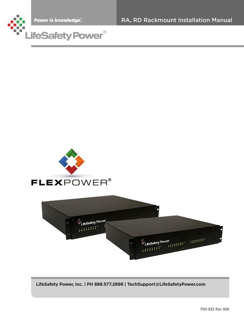
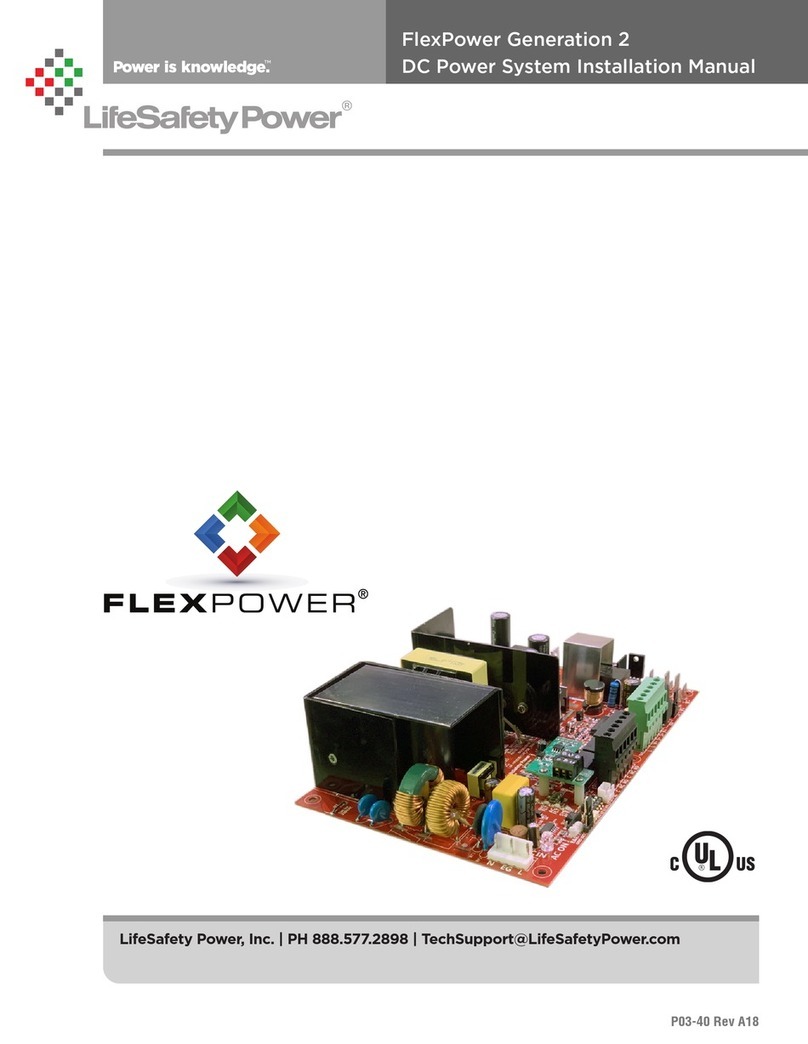
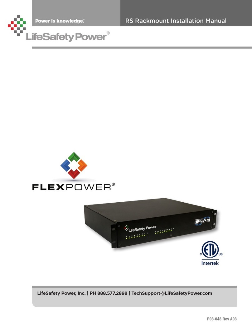
LifeSafety Power FlexPower User manual

LifeSafety Power, Inc. | PH 888.577.2898 | TechSupport@LifeSafetyPower.com
P03-003 Rev A09
AC Power System Installation Manual
FlexPower

FlexPower AC Power System Installation Manual
ii iii
FlexPower Features
VSelect®
Jumper selectable voltage of 24 or 28VAC by zone allows
for the reduction and simplification of service inventory by
eliminating the necessity of stocking units in each voltage.
FlexConnect®
The FlexPower series provides a prewired interconnection
system between the power supplies and accessory boards
of the power system that eliminates inter-module wiring
by the field installer. Field upgrading is as simple as using
common mounting footprints, predrilled mounting holes,
snap-in standoffs, and pluggable wires to add additional
system capability or capacity when needed.
Reliability+®
All power supplies within the FlexPower system are fully
fault protected and feature conformal coating on the elec-
tronic PC boards to protect the electronics from water, dust,
and other corrosive elements found in industrial settings.
GreenSmart®
All members of the FlexPower family are RoHs compliant,
lead-free, and meet the new state and federal requirements
for energy efficiency.
FlexPower Power Management System CCTV Standard Features
FlexPower's advanced feature set provides greater product reliability, increased flexibility, shorter install time, a smaller service
inventory, and an intelligent, economical solution to the problem of reliable system power.

FlexPower AC Power System Installation Manual
ii iii
Symbol Definitions
The following symbols are used throughout this manual.
hThis symbol is intended to alert the installer of shock haz-
ards within the enclosure. Service should only be per-
formed by qualified service personel.
iThis symbol is intended to alert the installer of impor-
tant information intended to help the installer avoid
personal injury or property damage.
Warnings
h Installation and service should be performed only by
qualified service personel and should conform to all
local codes.
h To reduce the risk of electric shock or fire, do not
expose this equipment to rain or moisture.
i This equipment shall be installed in a manner which
prevents unintentional operation by employees,
cleaning personel, or others working in the premesis,
by falling objects, customers, building vibration, or
similar causes.
i This equipment is not intended for use within the pa-
tient care areas of a Health Care Facility.
h Replace fuses only with the same type and rating as indi-
cated in the specifications section of this manual.
i To prevent impaired operation, ensure that all wiring is
routed and secured to prevent accidental open or short
circuit conditions.
Regulatory Information
The equipment discussed within this manual has been
tested to the following standards:
• UL2044
• UL294
• CSA C22.2 #107.1
Conventions Used Within this Manual
Positional information (eg. top, bottom, up, down, left,
right, etc.) is referenced with the board or enclosure in the
the orientation shown in the illustrations in this manual.
Notes and Warnings

FlexPower AC Power System Installation Manual
iv 1
Quick Install Guide
Table of Contents
FlexPower Features ..................................ii
Notes and Warnings .................................iii
Symbol Definitions..................................................iii
Warnings .........................................................iii
Regulatory Information ..............................................iii
Conventions Used Within this Manual ...................................iii
Table of Contents ................................... iv
Section 1 - Installation and Operation ......................1
1.1 Mounting...................................................... 1
1.2 Connections and Setup............................................2
1.2.1 Transformer Secondary Wire Colors ............................... 3
1.3 Typical Installation & Wire Routing .................................. 4
1.4 Power-Up and Basic System Verification Checklist ...................... 5
Section 2 - Troubleshooting and Maintenance ................6
2.1 Troubleshooting Chart............................................ 6
2.2 Maintenance Instructions ......................................... 6
Section 3 - Specifications ..............................7
3.1 Electrical Specifications........................................... 7
3.2 Temperature Specifications ........................................ 7
3.3 Mechanical Specifications......................................... 7
3.4 Replacement Parts .............................................. 8

FlexPower AC Power System Installation Manual
iv 1
Quick Install Guide
Enclosure-Level Products
Mounting an enclosure to a wall is via the two recessed
keyholes and two recessed mounting holes in the back of
the enclosure.
1. (Optional) Remove the enclosure’s cover.
2. Locate the top keyhole mounting holes in the back of the
enclosure.
3. Mark and pre-drill the locations for the keyholes in the
mounting surface.
4. Partially install two fasteners appropriate for the sur-
face on which the enclosure is being installed. Leave the
heads of the fasteners approximately ¼" out from the
surface. Minimum fastener size should be #10 or larger.
5. Hang the enclosure on the two fasteners and mark the
locations of the two bottom mounting holes.
6. Remove the enclosure and pre-drill the locations for the
two bottom mounting holes.
7. Re-hang the enclosure on the top mounting fasteners,
start the bottom two fasteners and tighten all fasteners.
8. Reinstall the enclosure’s cover, if removed in step 1.
i It is the installer’s responsibility to determine the ap-
propriate fastening system for use with the surface to
which the enclosure is being mounted.
Section 1 - Installation and Operation
1.1 Mounting

FlexPower AC Power System Installation Manual
2 3
Quick Install Guide
1AC Input (J9)
The primary AC input for the FPA Series power supplies. Multi-trans-
former supplies should have all transformer primaries connected to-
gether then connect to the AC Line. Input must be 120VAC 60Hz.
• White - Neutral
• Black - Hot
• Green/Yellow - Earth Ground
HAlways connect Earth Ground first and remove last
2A8(P) Board Zone Outputs
The zone outputs on the A8 boards distribute the transformer power
to the devices to be powered. These terminal strips are removable
and accept wire sizes from AWG14 - AWG22. Phasing is indicated on
the PC Board.
3Output Selection Jumpers (JP1 - JP8)
These jumpers select which voltage buss input is selected for the out-
put. Jumper numbers correspond with the zone number (eg. JP1 is
the jumper for OUT1). Possible settings are as follows:
• Position 2 (Left) - 28VAC (18V for 16.5/18V FPA models)
• Position 1 (Right) - 24VAC (16.5V for 16.5/18V FPA models)
• Removed - Disable Output
4Output Fuses (F1 - F8) - Optional
When using the fused version of the A8, these are the fuses for each
zone output. Fuse numbers correspond with the zone number (eg. F1
is the fuse for OUT1). When using the PTC version of the A8, the fuse
will be replaced with a soldered-in PTC.
5Output LEDs (D1 - A8) - Green
These LEDs indicate the availability of voltage on a zone’s output.
When voltage is available on the output terminals, the LED is lit. LED
numbers correspond with the zone number (eg. D1 is the LED for
OUT1).
1.2 Connections and Setup
HEnsure all power is disconnected before wiring.

FlexPower AC Power System Installation Manual
2 3
Quick Install Guide
1.2.1 Transformer Secondary Wire Colors
Brown
Common Voltage Current Voltage Current
FPA100A 0V 24V 4.17A 28V 3.57A
FPA150A 0V 24V 6.25A 28V 5.4A
FPA300A 0V 24V 12.5A 28V 10.7A
Brown
Common Voltage Current Voltage Current
FPA200A 0V 16.5V 6.06 18V 5.56A
Black
Common Voltage Current Voltage Current
0V 16.5V 6.06 18V 5.56A
FPA100/150/300AWinding1
FPA200AWinding2
White
Blue
Blue Orange
Yellow
FPA200AWinding1
Green

FlexPower AC Power System Installation Manual
4 5
Troubleshooting
1.3 Typical Installation & Wire Routing
The drawing above shows a typical installation. Actual con-
figuration and wire routing will vary based on the compo-
nents installed in your system. The following guidelines
should be followed for installation.
• Class 2 Power limited wiring must be separated from
non-power limited wiring by a minimum of 1/4 inch and
must use separate knockouts.
• AC Input Power must enter the enclosure via one of the
3/4" single knockouts
• The installation and all wiring methods shall be in ac-
cordance with ANSI/NFPA70 and all local codes.
• For Canadian Installations - For permanently connected
equipment, a readily accessible disconnect device shall
be incorporated external to the equipment. Output cir-
cuits not connected to removable terminal strips shall
also utilize a readily accessible disconnect device.
• Any wiring passing through knockouts in the bottom or
top surfaces of the enclosure must be enclosed in rigid
or flexible metal conduit.
AC Input
Class 2
Alternate
AC Input

FlexPower AC Power System Installation Manual
4 5
Troubleshooting
1.4 Power-Up and Basic System Verification Checklist
Q 1. Ensure proper configuration of all jumpers.
Q 2. Apply AC power to the FPA power supply.
Q 3. Ensure all green Zone LEDs are lit.
Q 4. Verify zone output voltage with a meter.
a. If the zone's jumper is set in position 1 , the
voltage should be approximately 24VAC
b. If the zone's jumper is set in position 2, the
voltage should be approximately 28VAC
Note that the exact voltage will vary with the
AC line voltage and loading

FlexPower AC Power System Installation Manual
6 7
Specifications
2.1 Troubleshooting Chart
Symptom Possible Problem Information / Possible Solution
No voltage on ALL Zones AC Input voltage missing Verify that 120VAC is present on the input of the transformer
Wire disconnected Verify that all wires are connected between the transformer and
the A8 board(s) in the system. Ensure that all crimp connections
are secure.
Transformer problem Verify that 24 and 28V (or 16.5 and 18V for 16.5/18V FPA Models)
are being output from the transformer. If not, the transformer's
internal protection may have opened. Contact LifeSafety Power.
A8 Board Problem Verify all jumpers and fuses are in place and intact. Contact Life-
Safety Power.
Incorrect voltage out of zone Zone jumper set incorrectly Verify the proper setting of the zone jumper
AC Input voltage incorrect Verify AC input is 120VAC
Improper wiring between
transformer and A8 board(s)
Verify the proper wiring between the transformer and A8 boards.
Contact LifeSafety Power for assistance.
2.2 Maintenance Instructions
The following are the maintenance instructions for the FPA
Series power supply system.
• Disconnect AC power prior to servicing
• Verify the integrity of all fuses (if used) and replace as
necessary using the fuse ratings supplied in the Speci-
fications section of this manual.
• Verify that all output voltages are within range as speci-
fied in the Specifications section of this document
Section 2 - Troubleshooting and Maintenance

FlexPower AC Power System Installation Manual
6 7
Specifications
3.1 Electrical Specifications
FPA Series Power Supplies
Specification FPA100A FPA150A FPA300A FPA600A FPA900A FPA200A
AC Input Voltage 120VAC ±15%
at 60Hz
120VAC ±15%
at 60Hz
120VAC ±15%
at 60Hz
120VAC ±15%
at 60Hz
120VAC ±15%
at 60Hz
120VAC ±15%
at 60Hz
Power 120 Watts 180 Watts 360 Watts 720 Watts 1080 Watts 240 Watts
Output Voltage 24/28VAC 24/28VAC 24/28VAC 24/28VAC 24/28VAC 16.5/18VAC
Total Current 4.1/3.5A 6.2/5.3A 12.5/10.7A 25/21.4A 37.5/32.1A 12/11A
Total Power 100 Watts 150 Watts 300 Watts 600 Watts 900 Watts 200 Watts
Current/Zone With A8
3A/zone max
With A8P
2.5A/zone max
With A8
3A/zone max
With A8P
2.5A/zone max
With A8
3A/zone max
With A8P
2.5A/zone max
With A8
3A/zone max
With A8P
2.5A/zone max
With A8
3A/zone max
With A8P
2.5A/zone max
With A8
3A/zone max
With A8P
2.5A/zone max
Fuse
Ratings
A8 ATM 3A ATM 3A ATM 3A ATM 3A ATM 3A ATM 3A
A8P N/A N/A N/A N/A N/A N/A
BTU Output BTU 68 102 204 410 612 137
3.2 Temperature Specifications
All Models
Ambient Temperature 0°C to 49°C (32°F to 120°F)
Ambient Humidity 93% at 32°C (90°F) maximum
Storage Temperature –30°C to 70°C (–22°F to 158°F)
3.3 Mechanical Specifications
Visit http://www.lifesafetypower.com/products/cctv-ac-power-systems for AutoCAD files.
FPA Transformers Size [Diameter x thickness] inches (mm) Approximate weight
100VA
150VA
200VA
300VA
3.6 x 1.5" (91 x 38 mm)
4.3 x 2.0" (109 x 51 mm)
4.6 x 1.9" (117 x 48 mm)
2.70 lbs (1.22 kg)
3.00 lbs (1.36 kg)
4.95 lbs (2.25 kg)
6.15 lbs (2.79 kg)
A8 / A8P Accessory
4.00 x 2.50 x 0.8" (102 x 64 x 20 mm) 0.14 lbs. (0.064 kg)
E1 Enclosure
12 x 14 x 4.5" (305 x 356 x 114 mm) 7.70 lbs. (3.49 kg) empty
E2 Enclosure
16 x 20 x 4.5" (406 x 508 x 114 mm) 12.30 lbs. (5.58 kg) empty
E5 Enclosure
11.25 x 8.63 x 3" (286 x 219 x 76 mm) 3.45 lbs. (1.56 kg) empty
Section 3 - Specifications

FlexPower AC Power System Installation Manual
8 PB
Section
3.4 Replacement Parts
All Models
Part # Description
A50-001 Replacement Transformer – 150VA, 24/28VAC Secondary, 120VAC Primary, Toroid
A50-002 Replacement Transformer – 300VA, 24/28VAC Secondary, 120VAC Primary, Toroid
A50-003 Replacement Transformer – 100VA, 24/28VAC Secondary, 120VAC Primary, Toroid
A50-004 Replacement Transformer – 200VA, 16.5/18VAC Secondary, 120VAC Primary, Toroid
A02-009 A8 Simple AC Distribution – Replacement Board
A02-010 A8P Simple AC Distribution (Class 2) – Replacement Board
A05-003 Accessory Board Cable Set – Short
A05-004 Accessory Board Cable Set – Long
A05-201 ATM-3 Fuse – Bag of 25
A05-301 Standoffs – Bag of 25
A05-302 Camlock Set
A11-002 NLR - NetLink network communication kit for remote output reset
P03-003 Rev A09 07/19
Important: All information, including illustrations, is believed to be reliable. Users, however, should independently
evaluate the suitability of each product for their particular application. LifeSafety Power makes no warranties as to the
accuracy or completeness of the information, and disclaims any liability regarding its use. LifeSafety Power’s only ob-
ligations are those in the LifeSafety Power Standard Terms and Conditions of Sale for this product, and in no case will
LifeSafety Power or its distributors be liable for any incidental, indirect, or consequential damages arising from the
sale, resale, use, or misuse of the product. Specifications are subject to change without notice. In addition, LifeSafety
Power reserves the right to make changes—without notification to Buyer—to processing or materials that do not affect
compliance with any applicable specification.
LifeSafety Power, FlexPower, NetLink, GreenSmart, FlexConnect, PowerCom, Reliability+, SureCharge, TruWatt, and VSelect are
trademarks or registered trademarks of LifeSafety Power Inc. or its affiliates.
© 2019 LifeSafety Power, Inc.All rights reserved
LifeSafety Power Inc.
899 E Park Avenue
Libertyville, IL 60048 USA
www.lifesafetypower.com
Tel (888) 577-2898
info1@lifesafetypower.com
Other manuals for FlexPower
1
Table of contents
Other LifeSafety Power Power Supply manuals

LifeSafety Power
LifeSafety Power FlexPower Generation 2 User manual

LifeSafety Power
LifeSafety Power FlexPower User manual

LifeSafety Power
LifeSafety Power FLEXPOWER RC75 Series User manual

LifeSafety Power
LifeSafety Power Helix User manual

LifeSafety Power
LifeSafety Power Helix RH150 Series User manual

LifeSafety Power
LifeSafety Power FlexPower RA150 Series User manual
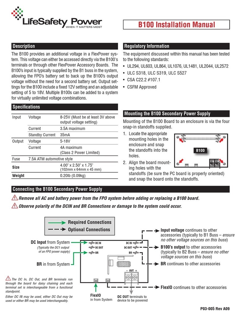
LifeSafety Power
LifeSafety Power B100 User manual

LifeSafety Power
LifeSafety Power FlexPower Vantage FPV4 User manual

LifeSafety Power
LifeSafety Power FLEXPOWER iSCAN RS Series User manual
LifeSafety Power
LifeSafety Power FlexPower Vantage R8 series User manual