manuals.online logo
Brands
  1. Home
  2. •
  3. Brands
  4. •
  5. Redback
  6. •
  7. Amplifier
  8. •
  9. Redback A 4310 User manual

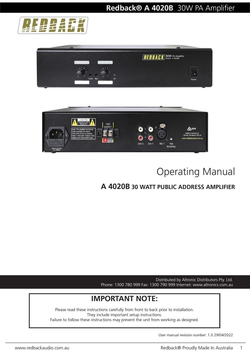
Redback A 4310 User manual

Please follow the instructions in this manual to obtain the optimum results from this unit.
We also recommend that you keep this manual handy for future reference.
OPERATION MANUAL
PUBLIC ADDRESS SYSTEM
4x120W / 4x240W CLASS-D AMPLIFIER
A 4314
A 4310
POWER
OFF
ON
5
0
1
2
3
4 6
7
8
9
10
5
0
1
2
3
4 6
7
8
9
10
5
0
1
2
3
4 6
7
8
9
10
5
0
1
2
3
4 6
7
8
9
10 PEAKPEAKPEAKPEAK SIGSIGSIGSIG CH4CH3CH2CH1 PROTPROTPROTPROT
A 4314
4 x 240W CLASS-D AMPLIFIER
POWER
OFF
ON
5
0
1
2
3
4 6
7
8
9
10
5
0
1
2
3
4 6
7
8
9
10
5
0
1
2
3
4 6
7
8
9
10
5
0
1
2
3
4 6
7
8
9
10 PEAKPEAKPEAKPEAK SIGSIGSIGSIG CH4CH3CH2CH1 PROTPROTPROTPROT
A 4310
4 x 120W CLASS-D AMPLIFIER
1. SAFETY PRECAUTIONS ...............................................................................1
3. FEATURES....................................................................................................3
4. NOMENCLATURE AND FUNCTIONS
4.1 Front Panel ...................................................................................... ...........4
4.2 Rear Panel..................................................................................................4
5. MACHINE OPERATION
5.1 Function......................................................................................................5
5.2 Read before using the amplifier..........................................................................5
5.3 Key operation on the panel................................................................................6
5.4 Remote operation..........................................................................................6
5.5 Select the input channel...................................................................................7
5.6 DC24V backup power (battery) power supply operation..............................................7
5.7 Function Operation of the Panel..........................................................................7
5.8 Indicator instruction of the panel.........................................................................7
6. CONNECTIONS ...............................................................................................8
. .............................................................................................9
. BLOCK DIAGRAM.......................................................................................10
9. ...........
2. PRODUCT OVERVIEW .................................................................................. 3
7
8
APPLICATIONS
SPECIFICATIONS.................................................................. 11
Be sure to read the instructions in this section carefully before use.
Make sure to observe the instructions in this manual as the conventions of safety symbols and messages
regarded as very important precautions are included.
We also recommend you keep this instruction manual handy for future reference.
Safety Symbol and Message Conventions
Safety symbols and messages described below are used in this manual to prevent bodily injury and property
damage which could result from mishandling. Before operating your product, read this manual first and
understand the safety symbols and messages so you are thoroughly aware of the potential safety
Indicates a potentially hazardous situation which, if mishandled, could
result in death or serious personal injury.
Indicates a potentially hazardous situation which, if mishandled, could
result in moderate or minor personal injury, and/or property damage.
Do not place cups, bowls, or other containers of
liquid or metallic objects on top of the unit. If they
accidentally spill into the unit, this may cause a
fire or electric shock.
Do not insert nor drop metallic objects or flammable
materials in the ventilation slots of the unit's cover,
as this may result in fire or electric shock.
When Installing the Unit When Installing the Unit
Should the following irregularity be found during
use, immediately switch off the power, disconnect
the power supply plug from the AC outlet and contact
y our nearest Redback dealer. Make no further
attempt to operate the unit in this condition as this
may cause fire or electric shock.
If you detect smoke or a strange smell coming
from the unit.
If water or any metallic object gets into the unit
If the unit falls, or the unit case breaks
If the power supply cord is damaged (exposure
of the core, disconnection, etc.)
If it is malfunctioning (no tone sounds.)
To prevent a fire or electric shock, never open nor
remove the unit case as there are high voltage
components inside the unit. Refer all servicing
to your nearest Redback dealer.
Do not expose the unit to rain or an environment
where it may be splashed by water or other liquids,
as doing so may result in fire or electric shock.
Use the unit only with the voltage specified on
the unit.Using a voltage higher than that which
is specified may result in fire or electric shock.
Do not cut,kink otherwise damage nor modify the
power supply cord. In addition, avoid using the
power cord in close proximity to heaters, and never
place heavy objects - including the unit itself - on
the power cord, as doing so may result in fire or
electric shock.
Be sure to replace the unit's terminal cover after
connection completion. Because high voltage
is applied to the speaker terminals, never touch
these terminals to avoid electric shock.
Be sure to ground to the safety ground (earth)
terminal to avoid electric shock. Never ground
to a gas pipe as a catastrophic disaster may result.
Avoid installing or mounting the unit in unstable
locations, such as on a rickety table or a slanted
surface. Doing so may result in the unit falling
down,causing personal injury and / or property
damage.
1. SAFETY PRECAUTIONS
1
SAFETY PRECAUTIONS
An all-pole mains switch with a contact separation of at least 3 mm in each pole shall be incorporated in
the electrical installation of the building.
Never plug in nor remove the power supply plug
with wet hands, as doing so may cause electric
shock.
When unplugging the power supply cord, be sure
to grasp the power supply plug; never pull on the
cord itself. Operating the unit with a damaged
power supply cord may cause a fire or electric
shock.
When moving the unit, be sure to remove its power
supply cord from the wall outlet. Moving the unit
with the power cord connected to the outlet may
cause damage to the power cord, resulting in fire or
electric shock. When removing the power cord, be
sure to hold its plug to pull.
Do not block the ventilation slots in the unit's cover.
Doing so may cause heat to build up inside the unit
and result in fire.
Avoid installing the unit in humid or dusty locations,
in locations exposed to the direct sunlight, near the
heaters, or in locations generating sooty smoke or
steam as doing otherwise may result in fire or
electric shock.
Do not place heavy objects on the unit as this may
cause it to fall or break which may result in personal
injury and/or property damage. In addition, the object
itself may fall off and cause injury and/or damage.
Make sure that the volume ontrol is set to minimum
position before power is switched on. Loud noise
produced at high volume when power is switched
on can impair hearing.
Do not operate the unit for an extended period of
time with the sound distorting. This is an indication
of a malfunction, which in turn can cause heat to
generate and result in a fire.
Contact your Redback dealer as to the clean-
ing. If dust is allowed to accumulate in the unit over
a long period of time, a fire or damage to the unit
may result.
If dust accumulates on the power supply plug or in
the wall AC outlet, a fire may result. Clean it peri-
odically. In addition, insert the plug in the wall outlet
securely.
Switch off the power, and unplug the power supply
plug from the AC outlet for safety purposes when
cleaning or leaving the unit unused for 10 days or
more. Doing otherwise may cause a fire or electric
shock.
Due to product upgrades, while some of the
features and specification in the user manual
does not match the actual functions, sorry for
any inconvenience and thanks for your kind
understanding!
When Installing the Unit When Installing the Unit
2
2. PRODUCT OVERVIEW
3.FEATURES
3
One channel high efficiency class D power amplifier
One channel power amplifier in 1U height.
RMS power output of 240W, 350W and 500W.
LED indicators for signal, peak, protection and power.
100V horn output interface.
Power amplifier 24V power port with supply voltage range ( 20V-25.6V ) protection,
avoid making battery long-term feeding failure or breakdown of internal circuit of
high voltage equipment.
Wide voltage (~190-240V 50/60Hz)to adjust to the work scope.
With DC24V backup (battery) function.
Built in high efficient Class D power amplifier.
100V speaker output interface.
Built-in active bandpass filter, effectively filter out unwanted music signal.
With remote control on/off switch function.
With remote monitor amplifier working status function.
Built-in short circuit, overload, high temperature protection.
The D series digital amplifier is rated from 120W to 500W with balanced signal inputs(H5.08-3
European-style connector) and 100V power outputs (H5.08-2 European-style connector).
CH 1 INCH 2 INCH 3 INCH 4 IN
CH 1 OUTCH 2 OUT
CH 3 OUT
CH 4 OUT
GGGG
COMCOMCOMCOM 10 0V1 00 V10 0V1 00V
~240V 50Hz
CH1 CH2
BATT SUPPLY
DC24V I NPUT
CH4
CH3
POWER
OFF
ON
5
0
1
2
3
4 6
7
8
9
10
5
0
1
2
3
4 6
7
8
9
10
5
0
1
2
3
4 6
7
8
9
10
5
0
1
2
3
4 6
7
8
9
10 PEAKPEAKPEAKPEAK SIGSIGSIGSIG CH4CH3CH2CH1 PROTPROTPROTPROT
A 4310
4 x 120W CLASS-D AMPLIFIER
5 6
78 9 10
11
12
7. ~240V 50Hz Power input
8. CH1/CH2/CH3/CH4 Spared (battery)
power interface
9. Cooling fan
10. CH1/CH2/CH3/CH4 100V speaker
output
1. CH1/CH2/CH3/CH4
Volume control of the channel
2. SIG
Signal Indicator
3. PEAK
Clip Indicator
4. PROT
Protection Indicator
5. POWER SWITCH
Up: turn on the power
Down: turn off the power
6. POWER
Power Indicator
4. NO ME NC LATU RE A ND F UN CTI ON S
4.1 FRONT PANEL
4.2 REAR PANEL
4
11. Balanced line input
by phoenix connector
12. CH1/CH2/CH3/CH4 Rj45 control port for
status monitoring and
remote power control
CH1/CH2/CH3/CH4
1234
5. MA CH IN E OP ERAT IO N
Amplifier Function
The role of amplifiers is to enlarge the audio signal from audio sources, such as MIC,
computer and MP3 etc. to boost speaker or pure amplifier to work.
Constant Voltage Amplifier
The output form of constant voltage amplifier output is constant voltage. It requires a certain
load of rated voltage. Constant voltage amplifier connects with speakers by the way of multiple
speakers in parallel form, as long as the total power does not exceed the amplifier total power,
there can be many speakers in a wire. Constant voltage amplifier output voltage is in fixed form,
in fact, the audio amplifier output voltage is subject to change, such as in a moment the constant
voltage amplifier output is 100V, in this moment, amplifier connects with a speaker, the power
amplifier output is 100V, connects with two three, or more speakers, the power amplifier output
is still 100V, of course, this is in the situation of enough power for the amplifier. This constant
voltage amplifier characteristics is very suitable for school to use, for example, in a school,there
are 24 classes, most students are in classroom, turn off the speakers, the speaker and the entire
broadcasting system is disconnected, it is because we use the constant voltage amplifier, a
speaker is disconnected, and it will not affect the voltage in the entire system line, so it will not
affect the broadcast in other classes. Constant voltage amplifier and speaker connections must
be parallel. In the public address system, the distance between speaker and amplifier may be
more far away, in shopping malls, machine room may be on the first floor, and as far as possible.
Function
Read Before Using The Amplifier
Volume Control
The volume depends on the performance of the speaker, position and some other factors. Pls avoid
to use the amplifier in the status of high volume for a long time.
Choice Of The Audio Source
In order to play the best performance of this device, please select the balanced signal sources after
processing by the preamplifier. Local input sensitivity is set to be 0dB (0.77V).
Connection Method
Please do not power on until all connections are completed. The audio cable connection need to
be fixed properly, otherwise it will reduce the sound quality, produce noise, or even damage the
device. Constant Voltage speakers are paralleled connected with the device (constant voltage
amplifier). In a supermarket, there is dozens or hundreds of speakers after an amplifier, these
speakers are on a wire. See wiring diagram of the device for the connection method, the load
with constant voltage speaker (100V) or all of the speakers, the power is not greater than the
power of the amplifier's rated output power.
5
CH 1 INCH 2 INCH 3 INCH 4 IN
CH 1 OUTCH 2 OUT
CH 3 OUT
CH 4 OUT
GGGG
COMCOMCOMCOM 10 0V100V100V100V
~240V 50Hz
CH1 CH 2
BATT SUPPLY
DC24V INPUT
CH4
CH3
POWER
OFF
ON
5
0
1
2
3
4 6
7
8
9
10
5
0
1
2
3
4 6
7
8
9
10
5
0
1
2
3
4 6
7
8
9
10
5
0
1
2
3
4 6
7
8
9
10 PEAKPEAKPEAKPEAK SIGSIGSIGSIG CH4CH3CH2CH1 PROTPROTPROTPROT
A 4310
4 x 120W CLASS-D AMPLIFIER
CH 1 INCH 2 INCH 3 INCH 4 IN
CH 1 OUTCH 2 OUT
CH 3 OUT
CH 4 OUT
GGGG
COMCOMCOMCOM 10 0V100V100V100V
~240V 50Hz
CH1 CH 2
BATT SUPPLY
DC24V INPUT
CH4
CH3
Figure 1
Figure 2
Connect power line AC 190~240V
After the device enter to working status, input balanced audio source signal in the rear
panel,adjust the volume potentiometer to select the appropriate volume. At this point,
it has completed the basic operation of the device.
Key operation on the panel
Remote operation
Figure 3
Turn the power switch button, after connecting the device to AC power, the front panel power
indicators, protection indicators and remote power indicators and remote protection indicators
lit at the same time, after about 3 seconds the light turns off. The amplifier built-in protection
relay closed, power amplifier and the output connection is regular. After device enters to the
working status, it has completed the device local power on operation. Press the power switch,
after power off, power indicators are off. Device power off operation is completed.
Connect DC+24V power supply, blue power indicator and red protection etc. according to the
marked graph of the remote terminal.
Connecting the remote network cable.
Input DC +24 V power supply, then the front panel power indicator light, and remote power
indicator, protection indicator lights at the same time, after about 3 seconds the protection
lights off, power amplifier is active and connected to the output. At this point, the device is
in working status.
6
MAC HI NE O PE RATI ON
POWER
OFF
ON
7
Function Operation of the Panel
Turning master volume control knob on the panel to adjust the volume. Turning clock-
wise slowly, volume gets higher; anti-clockwise, volume gets lower until zero level.
Remote port operation is prior than panel operations, namely when the front panel power
switch is off, the device can still be in power on status.
Cut off the input DC+24V power, then it can be remoted.
Select the input channel
Connecting "INPUT" at CH1, music signal source of balanced input 775mV,0dB at audio
cable, after connecting speaker with output terminal, then turn up volume knob, you could
hear the music.
And the operation of CH1, Ch2,CH3, Ch4 input method is the same.
DC24V backup power (battery) power supply operation
In the rear panel of the device DC24V backup power (battery) input port, "+" connect
with red positive battery termination, "-" connect with negative battery termination;
connecting the wires well as per requirements, connected with 24V DC power supply,
then it can be normal operation to use the device.
Indicator instruction of the panel
" OWER" Blue power indicator, If this signal light is on, the power source is connected.
" SIN" Green signal indicator ,When input audio source and turn on master volume
control knob, the indicator is gleaming. Turning up the volume, the indicator becomes
more bright,which means the signal output is greater.
"PEAK" Orange topping indicator ,When input audio source exceeds input standard
voltage,turn up the master volume control to the max level and turn on the voltage limita-
tion function. At 100V output of constant voltage, if the indicator lightens, it means the
amplifier is at clip state. It is proposed that the amplifier should not work in clip state for
a long time or it will be easily damaged.
"PROT" Red protection indicator ,When the amplifier is in the protection state of short-
circuit, overloading, overheating or fault, the indicator will lighten and cut off the output
at same time.
Attention: Under condition of overloading or unventilated environment, the amplifier will
get overheating. If the amplifier operates in such kind of state for a long time, to protect the
amplifier and speaker, it will automatically trigger thermal protection circuit and cut off the
output of amplifier or the power. After the temperature inside lowers to normal one, it will
recover automatically.
Note: The remote power indicator and power indicator on front panel is with the same
function, remote protection indicator and the protection indicator on front panel is with
the same function.
MAC HI NE O PE RATI ON
100V LINE
Total impedance 100V COM
Speaker connection:
Loosen the pressure screw.
Put the speaker cable under the wire clamp pad.
Tighten the pressure screw and make sure the
connection is good.
1.
2.
3.
NOTE:
100V output must be connected in parallel with the speakers, and should be connected
with the constant voltage speakers, constant voltage speaker is with built-in transformer,
there marked input voltage in back; if it connects with the constant resistance speakers,
it will be easy to damage the speakers .
When use the device, please do not directly touch the 100V speaker output
interface of the exposed metal parts in the rear panel to avoid electrical shock.
83 (A 4310)
42 ( )A 4314
6. CO NN EC TI ONS
8
Speaker connections
Attention:
Connect cable with the speaker, then with the host.
Speaker Selection: Constant Voltage 100V Speaker.
Please use black and red wire for the speaker line, connect black wire to speakers
terminal; the red wire connect with speakers' 100V marked at back, the other end
connect with the" 100V "terminal in the rear panel.
Avoid to operate the amplifier in full power state for a long time.
Do not connect the two speaker wires by short circuit way, to avoid damage the
equipment.
100V COM
CH 1 INCH 2 INCH 3 INCH 4 IN
CH 1 OUTCH 2 OUT
CH 3 OUT
CH 4 OUT
GGGG
COMCOMCOMCOM 10 0V100V100V100V
~240V 50Hz
CH1 CH 2
BATT SUPPLY
DC24V INPUT
CH4
CH3
7. AP PL IC AT IO NS
9
1: GND
2: COLD-
3: HOT+
When connecting, put the red cable to +
terminal at the host, white to "- " terminal,
and the shielded wire to the GND terminal.
The same connection to the output terminal
of the pre-audio source processor.
" "
1 2 3
G
Reserved PortReserved Port Reserved Port Reserved Port
REMOTE
AM/FM DTS TUNER
PREV NEXT USB/CD
EJECT PLAY STOP PLAY
MODE
MUTE
S D
USB
UP
6
AUTO/
MANUAL
5
4
MEM
3
ST/MON
AM/FM
2
1
DOWN
POWER
CD PLAYER
IR STATUS
1 1+2 2
OUTPUT OUTPUT OUTPUT
1 1+2 2 1 1+2 2
OUTPUT
1 1+2 2
OUTPUT
1 1+2 2
OUTPUT
1 1+2 2
OUTPUT
1 1+2 2
OUTPUT
1 1+2 2
OUTPUT
1 1+2 2
OUTPUT
1 1+2 2
OUTPUT
1 1+2 2
SIG SIG SIG SIG SIG SIG SIG SIG SIG SIG
LEVEL LEVEL LEVEL LEVEL LEVEL LEVEL LEVEL LEVEL LEVEL LEVEL LEVEL
2
3
456
7
8
10 0
19
2
3
456
7
8
10 0
19
2
3
456
7
8
10 0
19
2
3
456
7
8
10 0
19
2
3
456
7
8
10 0
19
2
3
456
7
8
10 0
19
2
3
456
7
8
10 0
19
2
3
456
7
8
10 0
19
2
3
456
7
8
10 0
19
2
3
456
7
8
10 0
19
2
3
456
7
8
10 0
19
0
2
3
456
7
8
10 0
19
2
3
456
7
8
10 0
19
0
00
HIGH
LOW
HIGH
+3 0 -3
-8
-13
MODE MODE MODE MODE MODE MODE MODE MODE MODE
P.T.T 1
CHIME
MASTER
1
LOW
MASTER
2
PRIORITY2
PRIORITY3
PRIORITY4
LINE
MIC
POWER
MASTER VOLUME
1
2
MASTER VOLUME
LINE
MIC
LINE
MIC
LINE
MIC
LINE
MIC
LINE
MIC
LINE
MIC
LINE
MIC
LINE
MIC
MIC/LINE 2 MIC/LINE 3 MIC/LINE 4 MIC/LINE 5 MIC/LINE 6 MIC/LINE 7 MIC/LINE 8 MIC/LINE 9 MIC/LINE 10
ON
CD PLAYER
PRE-AMPLIFIER
8. BL OC K DI AG RAM
10
LINE INPUT
Preamplifier
COM
100V
Preamplifier
CLASS-D AMP
Volume
SH-00531 SH-00497
SH-00497
AC 240V 50Hz
Power Factor Correction
SH-00497 Power Switch
GND
RJ45 Control
Power Control
SH-00503
PWM
SH-00497
Power supply
POWER transformer
24V Control
24V Battery
Power Inverter
PFC
24V
SH-00524 GND
limit
Control
band-pass
filter
SH-00497
60Hz -18dB 25KHz -12 dB
SPEKERS
PROT/POWER LED BUS
EMI
Gas tube lightning
MODEL
RATED POWDR OUTPUT
SPDADER OUTPUTS
INPUT SENSITIVITY AND IMPEDANDCE
Frequency response
100V
±385mV/20KΩ,Balanced H5.08 European-style
connector input
80Hz~18KHz(+1dB,-3 ) dB
S/N RATIO
THD
CONTROLS
INDICTORS
≥85dB
≤0.5% at 1KHz,1/3 rated power
Remote power control,volume control and status monitor
Signal,peak,protection and power
PROTECTION High temp,overload & short-circuit
DIMENSIONS
WEIGHT
484X390X44
POWDR CONSUMPTION
POWER SUPPLY
OVERLOAD SOURCE
ELECTROMOTIVE FORCE >11dB,Balanced H5.08 European-style connector input
9. SP EC IF IC AT ION S
11
A 4310 A 4314
4x240W4x120W
4X144W 4X288W
9Kg8.5Kg
~240V 50Hz
PUBLIC ADDRESS SYSTEM
VersionV0.1

This manual suits for next models

1

Other Redback Amplifier manuals

Redback A 4235A User manual

Redback

Redback A 4235A User manual

Redback PHASE 5 A 4264 User manual

Redback

Redback PHASE 5 A 4264 User manual

Redback A 4020B User manual

Redback

Redback A 4020B User manual

Redback A4260B User manual

Redback

Redback A4260B User manual

Redback Phase 5 A 4390A User manual

Redback

Redback Phase 5 A 4390A User manual

Redback PHASE 5 A 4390 User manual

Redback

Redback PHASE 5 A 4390 User manual

Redback A 4262B User manual

Redback

Redback A 4262B User manual

Redback A 4937 User manual

Redback

Redback A 4937 User manual

Redback A 4370A User manual

Redback

Redback A 4370A User manual

Redback A 4037 User manual

Redback

Redback A 4037 User manual

Redback A 4312 User manual

Redback

Redback A 4312 User manual

Redback A 4031C User manual

Redback

Redback A 4031C User manual

Redback A 4205 User manual

Redback

Redback A 4205 User manual

Redback A 4210 User manual

Redback

Redback A 4210 User manual

Redback A 4861 User manual

Redback

Redback A 4861 User manual

Redback A 1922A User manual

Redback

Redback A 1922A User manual

Redback A 4387A User manual

Redback

Redback A 4387A User manual

Redback A 4017 User manual

Redback

Redback A 4017 User manual

Redback PHASE 5 A 4395A User manual

Redback

Redback PHASE 5 A 4395A User manual

Redback A 4377A User manual

Redback

Redback A 4377A User manual

Redback A 1116 User manual

Redback

Redback A 1116 User manual

Redback A4260 User manual

Redback

Redback A4260 User manual

Redback A 4270 User manual

Redback

Redback A 4270 User manual

Redback A 4024 User manual

Redback

Redback A 4024 User manual

Popular Amplifier manuals by other brands

Musical Fidelity HT600 Instructions for use

Musical Fidelity

Musical Fidelity HT600 Instructions for use

Extron electronics XPA U 1004 SB Setup guide

Extron electronics

Extron electronics XPA U 1004 SB Setup guide

Sony TA-FA777ES operating instructions

Sony

Sony TA-FA777ES operating instructions

Wet Sounds SYN-DX Series owner's manual

Wet Sounds

Wet Sounds SYN-DX Series owner's manual

Cobalt Digital Inc 9242 product manual

Cobalt Digital Inc

Cobalt Digital Inc 9242 product manual

Omnitronic PAP Series user manual

Omnitronic

Omnitronic PAP Series user manual

Takstar E200W user manual

Takstar

Takstar E200W user manual

Toro 89-9747 installation instructions

Toro

Toro 89-9747 installation instructions

Alto MISTRAL900 user manual

Alto

Alto MISTRAL900 user manual

musikelectronic geithain RL-Amplifier 2 Instructions for installation and use

musikelectronic geithain

musikelectronic geithain RL-Amplifier 2 Instructions for installation and use

Dynacord CL 800 Specification sheet

Dynacord

Dynacord CL 800 Specification sheet

Mesa 7I33 manual

Mesa

Mesa 7I33 manual

Two-Rock TS-1 owner's manual

Two-Rock

Two-Rock TS-1 owner's manual

Autonics BF5 Series product manual

Autonics

Autonics BF5 Series product manual

Shinybow USA SB-3770 instruction manual

Shinybow USA

Shinybow USA SB-3770 instruction manual

Hafler P230 Assembly and operation instructions

Hafler

Hafler P230 Assembly and operation instructions

Maxon bd10 user guide

Maxon

Maxon bd10 user guide

Pioneer PRS-D400 owner's manual

Pioneer

Pioneer PRS-D400 owner's manual

manuals.online logo
manuals.online logoBrands
  • About & Mission
  • Contact us
  • Privacy Policy
  • Terms and Conditions

Copyright 2025 Manuals.Online. All Rights Reserved.