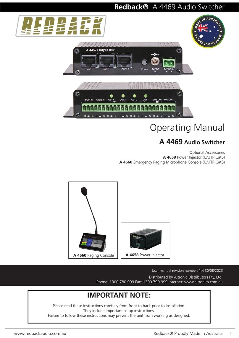
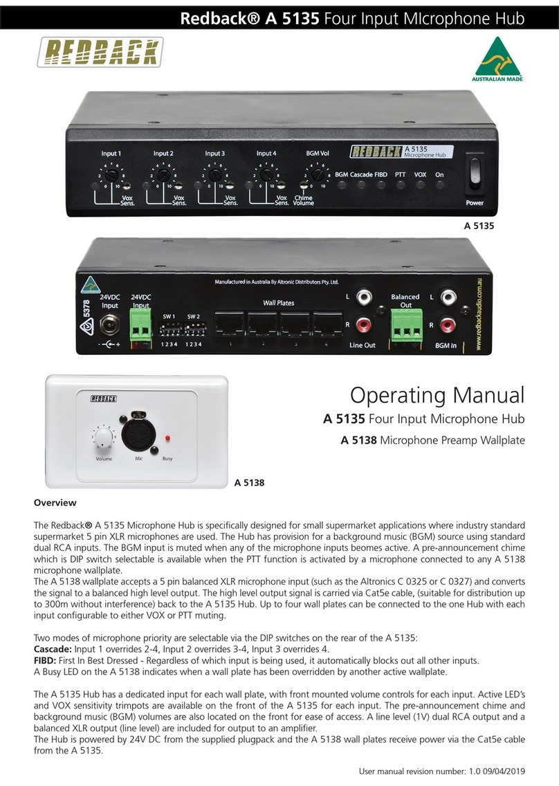
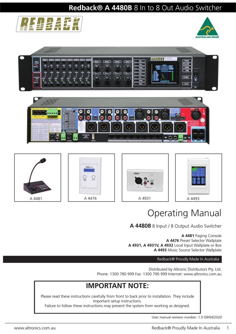
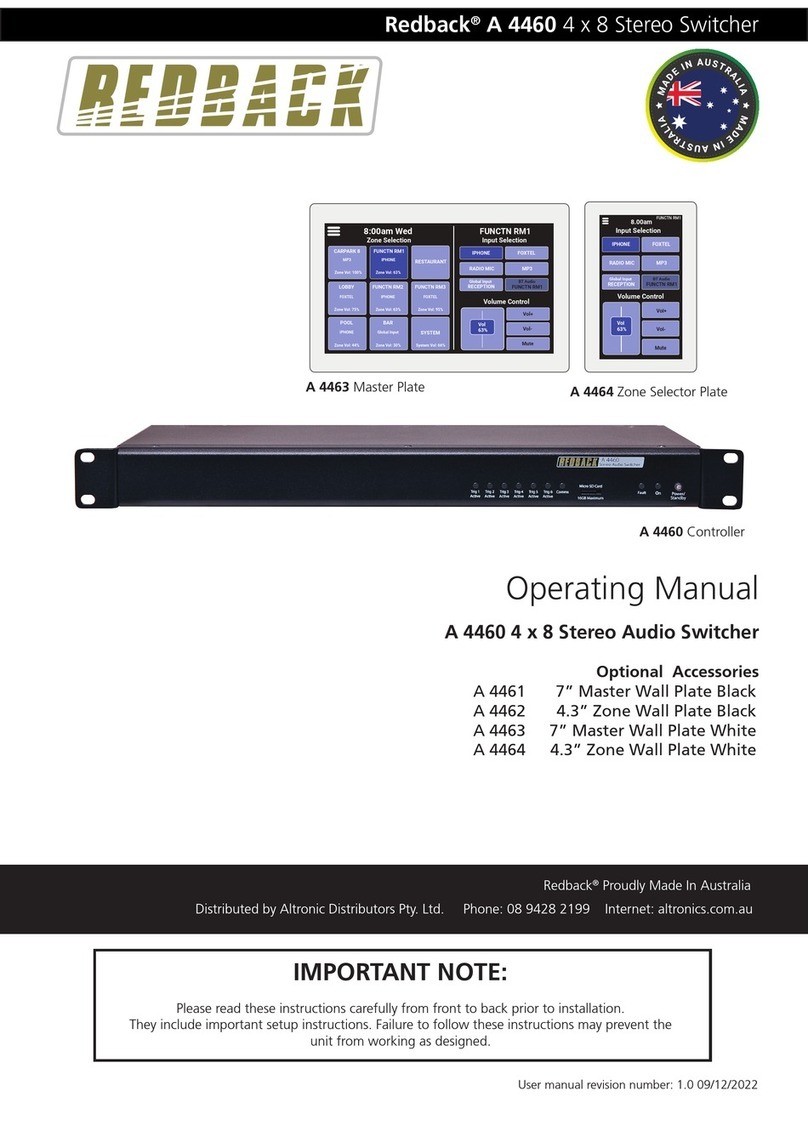
Redback A 4450 User manual

Redback®A 4450 4 x 4 Audio Matrix/Switcher
User manual revision number: 1.5 25/11/2022
Operating Manual
A 4450 4 x 4 Audio Source Matrix/Switcher
Optional Accessories
A 4461 7” Master Wall Plate Black
A 4462 4.3” Zone Wall Plate Black
A 4463 7” Master Wall Plate White
A 4464 4.3” Zone Wall Plate White
A 4660 Paging Microphone Console
IMPORTANT NOTE:
Please read these instructions carefully from front to back prior to installation.
They include important setup instructions. Failure to follow these instructions may prevent the
unit from working as designed.
Redback®Proudly Made In Australia
Distributed by Altronic Distributors Pty. Ltd. Phone: 08 9428 2199 Internet: altronics.com.au
A 4461 Master Plate A 4464 Zone Selector Plate
A 4660 Paging Console
A 4450 Controller

www.redbackaudio.com.auRedback® Proudly Made In Australia2
Redback®A 4450 4 x 4 Audio Matrix/Switcher
REDBACK is a registered trademark of Altronic Distributors Pty Ltd
You may be surprised to learn that Altronics is still manufacturing hundreds of product lines right here in Australia. We
have resisted the move offshore by offering our customers better quality products with innovations to save them time and
money.
Our Balcatta production facility manufactures/assembles:
Redback public address products
One-shot speaker & grill combinations
Zip-Rack 19 inch rack frame products
We strive to support local suppliers wherever possible in our supply chain, helping to support Australia’s manufacturing
industry.
Redback Audio Products
100% developed, designed & assembled in Australia.
Since 1976 we have been manufacturing Redback ampliers in Perth, Western Australia. With over 40 years experience
in the commercial audio industry, we offer consultants, installers and end users reliable products of high build quality with
local product support. We believe there is signicant added value for customers when purchasing an Australian made
Redback amplier or PA product.
Local support & feedback.
Our best product features come as a direct result of feedback from our customers, and when you call us, you speak to a
real person - no recorded messages, call centres or automated push button options.
It’s not only the assembly team at Altronics who are employed as a direct result of your purchase, but hundreds more at
local companies used in the supply chain.
Industry leading 10 year warranty.
There’s a reason we have the industry leading DECADE warranty. It’s because of a long tried and tested history of bullet-
proof reliability. We’ve heard PA contractors tell us they still see the original Redford amplier still in service in schools.
We offer this comprehensive parts & labour warranty on almost every Australian Made Redback public address product.
This offers both installers and end users peace of mind that they will receive prompt local servicing in the rare event of any
problems.
Published by Altronic Distributors
© 2022 Altronic Distributors

www.redbackaudio.com.au Redback® Proudly Made In Australia 3
Redback®A 4450 4 x 4 Audio Matrix/Switcher
CONTENTS
Page
1.0 Introduction 4
2.0 Features 4
3.0 What’s in the box 4
4.0 Front panel guide 5
5.0 Rear panel guide 6
6.0 Front Panel Operation 7
7.0 input and Output Labels 7
8.0 Master Wallplate Operation (Matrix Mode) 8
9.0 Zone Wallplate Operation (Matrix Mode) 9
10.0 Master Wallplate Operation (Selector Mode) 10
11.0 Zone Wallplate Operation (Selector Mode) 11
12.0 APP Operation 11
13.0 Wallplate Settings Menu 12
14.0 Paging Console 13
15.0 Paging Console Settings Menu 15
16.0 DIP Switch Settings 16
17.0 Wallplate and Paging Console Connection Details 17
18.0 Serial Protocols and Third Party Control 18
19.0 Serial Connection Details 19
20.0 Firmware Update 20
21.0 Specications & Warranty 20

www.redbackaudio.com.auRedback® Proudly Made In Australia4
Redback®A 4450 4 x 4 Audio Matrix/Switcher
1.0 INTRODUCTION
The A4450 master unit can be congured to operate as either a 4x4 Matrix, allowing any combination of inputs to be
selected to an output, or as a Switcher, enabling only one input to be selected to an output at any time. This is set by
the installer via a DIP switch on the rear panel. Note it cannot be congured to work as both. It is set as either a matrix, or
switcher. Any connected wallplates will automatically be set to suit the master unit.
Feature packed yet simple to set up and use, this mixer pairs with easy to use wallplate controllers. With 4 inputs selecta-
ble to up to 4 output zones it is ideally suited to gyms, cafes, restaurants, small clubs and function centres.
Designed with end users in mind, this complete audio source controller for buildings and venues provides source selection
and level control from remotely located wallplate controllers located up to 200m from the main unit. Multiple inputs can
be selected/mixed to an output zone as desired. The controller offers a visual indication of which input is selected to which
output on the front panel LCD and illuminated controls.
It accepts both balanced mic (pluggable screw terminals) and line level signals (stereo RCA) for four audio sources and
switches them to matching individual output zones. Any or all inputs can be switched to any and all output zones.
For added convenience all inputs and output zones can be labelled for display on the LCD. This allows users to quickly see
the source playing in each output zone.
A total of 8 remote wall plates and 2 paging consoles can be used on the system. Maximum of 2 plates per cable run (in
parallel or chained via extension connector on rear of plate). The A4660 paging console also includes the functionality of
a master control plate.
If required, the system can be controlled using standard RS-232 control codes for third party control systems.
2.0 FEATURES
• 4 mic/line inputs to 4 zones
• Matrix or selector modes
• Touchscreen & iOS/Android app control
• Adjustable aux level 100mV/1V
• Adjustable balanced mic/line level 3mV/0.7V
• LCD for easy selection of sources to output zones
• LCD provides indication of active sources and output levels
• System cabling via Cat5e UTP.
• Zone and input custom labelling
• Adjustable volume for each input to output selection
• Master & zone source selection wallplates (optional)
• Paging Console (optional)
• Serial control
• 24V DC operation
3.0 WHAT’S IN THE BOX
A 4450 4 x 4 Audio Matrix
24V 2A DC Plugpack
Instruction Booklet
NOTE: Each optional zone, master wallplate or paging console MUST have a
unique ID. Please see section 13.0. Wallplate setting menu “Set Unit Address”.

www.redbackaudio.com.au Redback® Proudly Made In Australia 5
Redback®A 4450 4 x 4 Audio Matrix/Switcher
4.0 FRONT PANEL GUIDE
Fig 1 shows the layout of the A 4450 front panel.
Fig 1
1 Output zone 1 inputs selector
Use these switches to select which input source/s will be sent to output zone 1.
2 Output zone 2 inputs selector
Use these switches to select which input source/s will be sent to output zone 2.
3 Output zone 3 inputs selector
Use these switches to select which input source/s will be sent to output zone 3.
4 Output zone 4 inputs selector
Use these switches to select which input source/s will be sent to output zone 4.
5 Volume
Use this control to adjust the volume of the output zone.
6 LCD Display
This displays the input and output labels and the volume levels.
7 Signal Presence Indicator
This LED indicates when a signal is present at the current output zone.
8 LED VU Meter
This LED bar graph provides a visual indication of the signal at the current output zone.
9 On Indicator
This LED indicates when the unit has power.
10 Standby Switch
When the unit is in standby mode this switch will illuminate red. Press this button to switch the unit ON. Once the
unit is ON the On indicator will illuminate blue. Press this switch again to put the unit back in standby mode.
1 2 3 4 5 8910
67
On
Standby
Power/
Signal
Present
-12dB -9dB -6dB -3dB 0dB-15dB
Volume
Input/Output Selection
Inputs
Output 1
1 2 34
Output 2
1 2 34
Output 3
1 2 34
Output 4
1 2 34Inputs
Outputs
Inputs
4
3
2
1
4
3
2
1
24 Hour 7 Day Timer
A 4500
4 x 4 Audio Switcher
A 4450

www.redbackaudio.com.auRedback® Proudly Made In Australia6
Redback®A 4450 4 x 4 Audio Matrix/Switcher
5.0 REAR PANEL GUIDE
Fig 2 shows the layout of the A 4450 rear panel.
Fig 2
1 RCA Inputs
These line inputs are dual RCA connectors which are internally mixed to produce a mono input signal. The input
sensitivity of these inputs can be adjusted to 100mV or 1V via the switches 2 & 3 of DIP1 & DIP2.
2 Microphone Inputs
There are four microphone inputs which all incorporate a 3 way euro connectors. The input sensitivity of these
inputs can be adjusted to 3mV or 0.7V via the switches 1 & 4 of DIP1 & DIP2. Phantom power is available for
electret type microphones.
3 DIP Switches DIP1 & DIP2
These are used to select the input sensitivities of the aux and mic inputs. Refer to DIP switch settings section (16.0).
4 RCA Outputs
These line outputs are dual RCA connectors which are internally separated from a mono signal. The
sensitivity of these outputs can be adjusted to 100mV or 1V via the switches of DIP3.
5 Balanced Outputs
There are four balanced outputs which all incorporate a 3 way euro connector. The sensitivity of these
outputs are tied to the sensitivities of the RCA outputs. These are set by DIP3.
6 DIP Switches DIP3
These are used to select the output sensitivities of the aux and balanced outputs. Refer to DIP switch settings.
7 Paging Console RJ45 Interface
These are used to connect optional paging consoles (A 4660). Maximum 2 consoles.
8 Wall Plate RJ45 interface
These RJ45 ports connect to the optional A 4461/63 Master and A 4462/64 Zone wall plates.
9 RJ45 Interface Port
For serial control. See section 18.0.
10 DIP 4
These switches provide various options (see DIP switch settings 14.0 for more details).
11 Micro SD Card Socket
This is used for input and output labelling and rmware updates. A micro SD card is supplied.
12 24V DC Input (Backup)
Connects to a 24V DC backup supply with at least 2A current capacity (please observe the polarity).
13 24V DC input
Connects to a 24V DC 2A plug pack with 2.1mm jack (centre tip positive).
www.redbackaudio.com.au
Made in Australia
by Altronic Distributors
+-
+_
DIP 4
1 2 3 4
Micro
24V
DC In
Console 2
SD Card
Adapter
24V
DC In
DIP 1
L
R
Aux In 1Aux In 2
L
R
Mic 1
Mic 2
1 2 3 4
DIP 1
L
R
Aux In 3
Aux In 4
L
R
Mic 3
Mic 4
1 2 3 4
DIP 2
DIP 1
L
R
Aux Out 1Aux out 2
Out 2 Out 1
L
R
Aux Out 3
Aux Out 4
L
R
Out 3
Out 4
1 2 3 4
DIP 3
Input 3 Input 2 Input 1
Input 4
Console 1
Wall Plates
Outputs
3
8910111213 75
1
4
23
6
1 2 3 41 2 3 41 2 3 4
1 2 3 4

www.redbackaudio.com.au Redback® Proudly Made In Australia 7
Redback®A 4450 4 x 4 Audio Matrix/Switcher
6.0 FRONT PANEL OPERATION
The LCD lists the inputs on the left side, the output zones on the right side and displays the volume level in the centre. The
labels for the inputs and outputs can be customised by the user (see section 7.0 for details).
When the A 4450 is in Matrix Mode (Refer to DIP switch setings) any or all of the four inputs can be mixed independently
into any or all of the four output zones of the Matrix. The inputs are selected by the switches on the front panel, which are
grouped together under each of the output zone labels. This is represented by numbers 1- 4 of gure 1.
When the A 4450 is in Switcher Mode (Refer to DIP switch setings) only one input can be selected per output.
To select an input, press the corresponding numbered button. Once selected the switch will ash and the LCD will display
the status of this switch.
For example if Input 3 of the Output zone 2 group (i.e. button 3 from the input 2 group) is selected, the corresponding
switch will ash and the Input 3 and Output zone 2 labels on the LCD will be highlighted as illustrated in gure 3. The
switch will ash for about 10 seconds (unless another switch is activated) and the volume level of Input 3 for Output zone
2 will be displayed on the LCD. While the switch is ashing the volume can be adjusted using the volume control on the
front of the unit.
Note: adjusting the volume adjusts only the volume for the input and output zone combination displayed on the LCD.
Fig 3
Once the switch stops ashing, the switch will stay illuminated to indicate this input is on. To deselect the input, press and
hold the button until the switch light turns off.
If another input is required for output zone 2, then the corresponding input switch can be pressed and the process repeat-
ed.
If the unit is in Matrix Mode all four inputs can be switched on and mixed into output zone 2 if required. The same process
can be repeated for the other input/output congurations.
7.0 INPUT & OUTPUT LABELS
The inputs and outputs which are displayed on the LCD, can be easily customised by making changes to the text les on
the supplied Micro SD card or alternatively use the master wallplate control (see section 13.0). To change the labels via SD
card follow the steps outlined below:
1. Disconnect power from the A 4450.
2. Remove the Micro SD card from the rear of the A 4450 by pushing it in until it clicks, and then releasing it.
3. Insert the Micro SD card into a PC or Laptop with a Micro SD slot. (If the computer doesn’t have this, a compatible
Micro SD card reader will be required).
4. Navigate to and select the Micro SD card.
5. Inside the card will be folders labelled “Inputs” and “Outputs”.
6. To change the Input labels, select the Inputs folder and open the relevant text le. I.e. The “Label2.txt” le to change
the Input 2 label. Once the le is opened with a text editor, change the label to something meaningful to
a maximum of 10 characters (only standard keyboard characters are accepted).
7. Repeat step 6 for the output labels.
8. Once complete, follow windows safe removal procedures for ejecting the Micro SD card.
9. With power still disconnected from the A 4450, insert the Micro SD card. Push it in until it clicks.
10. Reconnect power to the A 4450 and press the “Power/Standby” switch to turn the unit on.
11. The new labels should now be displayed on the LCD.
12. Remove the Micro SD card from the rear of the A 4450 by pushing it in until it clicks, and then releasing it.
(Note: Do not leave the micro SD card inside the A 4450.
On
Standby
Power/
Signal
Present
-12dB -9dB -6dB -3dB 0dB-15dB
Volume
Input/Output Selection
Inputs
Output 1
1 2 34
Output 2
1 2 34
Output 3
1 2 34
Output 4
1 2 34Inputs
Outputs
Inputs
4
3
2
1
4
3
2
1
24 Hour 7 Day Timer
A 4500
4 x 4 Audio Switcher
A 4450
DAB RADIO
DAB RADIO 2
MP3 PLAYER
MAIN BAR
COURTYARD
FOYER
PAY TV
ALFRESCO
VOLUME
52

www.redbackaudio.com.auRedback® Proudly Made In Australia8
Redback®A 4450 4 x 4 Audio Matrix/Switcher
8.0 MASTER WALLPLATE OPERATION (MATRIX MODE)
Fig 3
1 Settings Button
Tap this to access settings to adjust output zone / audio source names, colour themes and backlight settings.
2 Zone Selection Area
This area is used to toggle between the four output zones to adjust to source selection & level control.
3 Output Zone Name
The name of the output zone that sources are displayed for.
4 Input & Volume Selection Area
This area is used to adjust the four audio sources in the chosen output zone.
5 Volume +/- Buttons
Use these buttons to make ne adjustments to level control.
6 Volume Slider
Touch and slide the volume of a chosen audio source up and down as desired.
7 On/Off Selector
Switches an audio source on or off for the chosen output zone. Volume will display at last used setting.
8 Audio Source Name
The name of the audio source.
OPERATION
The master wallplate connects to the controller via Cat5e UTP or similar cabling and can be located up to 200m away. Up
to two plates (master or zone) can be connected on a single cable run, with a maximum of 8 wallplates per system.
The master wallplate allows for audio source selection and level control for every output zone. The left side of the screen
displays the output zones with the custom zone labels you have selected in section 7.0. Below the name, the status of
each audio source and volume level is displayed.
To make changes, tap the output zone you desire on the left and use the volume slider, volume +/- buttons or on/off selec-
tor to make adjustments to the mixed audio output in that zone.
For example, if you wanted to turn the “radio mic” on in “Function RM1”, you would tap the “Function RM1” output
zone on the left, then press the “Off” button associated with the Radio Mic. The source will change colour and the enable
button will display “ON” indicating it is switched on, and the volume will be set to the last used setting.
To adjust the colour theme, tap the menu icon on the top left of the screen. See section 13.0 for information on wallplate
settings.
Zone Selection FUNCTN RM1
Input & Volume Selection
DAB RADIO FOXTEL
RADIO MICROCK RADIO
DAB RADIO : 50%
FOXTEL : 45%
RADIO MIC : OFF
ROCK RADIO : 67%
FUNCTN RM1
DAB RADIO : OFF
FOXTEL : 43%
RADIO MIC : OFF
ROCK RADIO : OFF
RESTAURANT
DAB RADIO : 55%
FOXTEL : OFF
RADIO MIC : 25%
ROCK RADIO : OFF
GARDEN
DAB RADIO : OFF
FOXTEL : OFF
RADIO MIC : 55%
ROCK RADIO : 50%
LOUNGE
Vol
50%
On
Vol-
Vol+
Vol
45%
On
Vol-
Vol+
Vol
67%
On
Vol-
Vol+
Vol
43%
Off
Vol-
Vol+
1
2
4
3
5
6
7
8

www.redbackaudio.com.au Redback® Proudly Made In Australia 9
Redback®A 4450 4 x 4 Audio Matrix/Switcher
9.0 ZONE WALLPLATE OPERATION (MATRIX MODE)
1 Settings Button
Tap this to access zone wallplate settings ie: to adjust wall
plate colour theme and backlight settings.
2 Volume Slider
Touch and slide the volume of a chosen audio source up and
down as desired.
3 Volume +/- Buttons
Use these buttons to make ne adjustments to level control.
4 On/Off Selector
Switches an audio source or or off in the zone. Volume will
display at last used setting.
5 Output Zone Name
The name of the output zone.
6 Audio Source Name
The name of the audio source.
Fig 4
OPERATION
The zone wallplate or paging console connects to the controller via Cat5e UTP or similar cabling and can be located up to
200m away. Up to two plates (master or zone) can be connected on a single cable run, with a maximum of 8 wallplates
per system.
The zone wallplate allows for audio source selection and level control for the zone in which its located. This wallplate dis-
plays the status of the four audio sources and their respective volume levels.
To make changes, simply tap the volume +/- buttons or switch an audio source on or off using the on/off selector. When
an audio source is switched off, the controls will display in a darker colour.
To adjust the colour theme, tap the three lines icon on the top left of the screen. See section 13.0 for information on wall-
plate settings.
DAB RADIO FOXTEL
RADIO MICROCK RADIO
LOUNGE
Vol
62% Vol-
Vol+
Off Vol
7%
Vol-
Vol+
Off
Vol
50% Vol-
Vol+
On
Vol
55% Vol-
Vol+
On
1
2
3
4
5
6

www.redbackaudio.com.auRedback® Proudly Made In Australia10
Redback®A 4450 4 x 4 Audio Matrix/Switcher
10.0 MASTER WALLPLATE OPERATION (SELECTOR MODE)
Fig 5
1 Settings Button
Tap this to access settings to adjust output zone / audio source names, colour themes and backlight settings.
2 Zone Selection Area
This area is used to toggle between the four output zones to adjust to source selection & level control.
3 Output Zone Name
The name of the output zone that sources are displayed for.
4 Input Selection Area
This area is used to select between the four audio sources in the chosen output zone.
5 Volume Slider
Touch and slide the volume of a chosen audio source up and down as desired.
6 Volume +/- Buttons
Use these buttons to make ne adjustments to level control.
7 Muting On/Off Selector
Switches an muting on or off for the chosen output zone. Volume will display at last used setting.
OPERATION
The master wallplate connects to the controller via Cat5e UTP or similar cabling and can be located up to 200m away. Up
to two plates (master or zone) can be connected on a single cable run, with a maximum of 8 wallplates per system.
The master wallplate allows for audio source selection and level control for every output zone. The left side of the screen
displays the output zones with the custom zone labels you have selected. Below the name, the status of the selected audio
source and volume level is displayed.
Note: In selector mode only one audio source can be selected at a time.
To make changes, tap the output zone you desire on the left. Then select an audio source and adjust the level using the
volume slider or volume +/- buttons. Muting can also be switched on and off.
Zone Selection DINING
Input Selection
Volume Control
DAB RADIO : 50%
FAMILY
DAB RADIO 2 : 50%
DINING
KITCHEN PATIO
Vol
50% Vol-
Vol+
FOXTEL : 100%
MP3 PLAYER
Mute Active
Mute
OFF
FOXTEL
DAB RADIO DAB RADIO 2
MP3 PLAYER
1
2
4
3
5
6
7

www.redbackaudio.com.au Redback® Proudly Made In Australia 11
Redback®A 4450 4 x 4 Audio Matrix/Switcher
11.0 ZONE WALLPLATE OPERATION (SELECTOR MODE)
1 Settings Button
Tap this to access zone wallplate settings ie: to adjust wall
plate colour theme and backlight settings.
2 Audio Source Input Selection Buttons
Choose between the audio sources connected to the system.
3 Volume Slider
Touch and slide the volume of a chosen audio source up and
down as desired.
4 Output Zone Name
The name of the output zone.
5 Volume +/- Buttons
Use these buttons to make ne adjustments to level control.
6 Mute On/Off Selector
Switches an muting or or off in the zone. Volume will
display at last used setting.
Fig 6
OPERATION
The zone wallplate or paging console connects to the controller via Cat5e UTP or similar cabling and can be located up to
200m away. Up to two plates (master or zone) can be connected on a single cable run, with a maximum of 8 wallplates
per system.
The zone wallplate allows for audio source selection and level control for the zone in which its located. This wallplate dis-
plays the status of the chosen audio source and the current audio volume level.
To make changes, simply tap the volume +/- buttons, use the volume slider or activate muting using the mute On/Off
selector.
To adjust the colour theme, tap the three lines icon on the top left of the screen. See section 13.0 for information on wall-
plate settings.
12.0 APP OPERATION
iOS/Android app under development. The app will connect to the local zone wallplate via Bluetooth and allow adjustments
of source and level control in that zone.
FAMILY
Input Selection
Volume Control
FOXTEL
DAB RADIO DAB RADIO 2
MP3 PLAYER
Vol
50% Vol-
Vol+
Mute
OFF
1
2
3
4
5
6

www.redbackaudio.com.auRedback® Proudly Made In Australia12
Redback®A 4450 4 x 4 Audio Matrix/Switcher
Adjust
Backlight
System
Actions
Set Unit
Address
Set Access
PIN
Change
Labels
Colour
Scheme
Back
Set Plate
Zone
Set Unit
Address
Adjust
Backlight
System
Actions
Set Access
PIN
Colour
Scheme
Back
13.0 WALLPLATE SETTINGS MENU
Each wallplate has a settings menu which can be accessed using the icon on the top left of the screen (marked 1 in gure
3 & 4). Once in this menu the following screen will be displayed.
Fig 7 - Wallplate Settings. Master (left), Zone (right).
Adjust backlight - Allows you to select active brightness and dimmed brightness levels of the wallplate with the time out
period selectable for each level before the wallplate switches the screen off.
System actions - Allows you to choose settings for audible feedback on touch (on/off), screen rotation and wallplate/fac-
tory reset functions.
Set unit address - Each wallplate in the system must have a unique address from 1 to 16. This setting allows you to enter
the address for the plate you are using. Blanked out numbers are addresses already in use.
Set access PIN - Set an optional access PIN preventing unauthorised access to the wallplates settings. Type in a preferred
PIN and press “E” to accept. Press “C” to delete pin digits or reset PIN.
Change labels (master wallplate only) - Allows you to set and change the custom labels for the output zones and
audio sources.
Colour scheme - Set button colour scheme to preset red, blue or black/white. Note that other colour schemes can be
provided via rmware update.
Set plate zone (Zone wallplate only) - Allows you to select which zone the wallplate is operating in.

www.redbackaudio.com.au Redback® Proudly Made In Australia 13
Redback®A 4450 4 x 4 Audio Matrix/Switcher
Zone Selection
RESTAURANT
SWITCH TO ZONE CONTROL
FUNCTN RM1
GARDEN
LOUNGE
Paging
RECORDINGS
ALL CALL
CANCEL
PAGE
Press (<1s) to activate.
Hold for non-locking activation.
1
2
3
4
5
6
7
14.0 A 4660 PAGING CONSOLE
The optional A 4660 acts both as a paging console and a master control wallplate.
The paging console connects to the A 4450 controller via Cat5e UTP or similar cabling
and can be located up to 200m away. Connection is made to the rear of the A 4450 using
either of the ports labelled “Console 1” and “Console 2”. Refer to gure 13 for connection
details.
Note: Do not connect the paging consoles to the ports labelled “Wall Plates”
PAGING OPERATION
Zone selection for paging is shown on the left hand side of the screen, whilst on the right
hand side a “Page” button can be pressed to commence paging to your chosen zone (see
gure 8). A chime will play prior to paging if enabled in “Microphone Settings”.
To access Zone Selection functionality press the “Switch to Zone Control” button.
Fig 8. A 4660 Paging Screen
1 Settings Button
Tap this to access settings to adjust output zone / audio source names, colour themes, backlight settings and
paging settings.
2 Zone Paging Selection
This area is used to select a zone to page.
3 Switch to zone control mode
Switches the screen to Zone Control Mode to make adjustments to audio sources / levels.
4 Recordings
Access pre-recorded announcements for paging (ie: closing time, re alarm test announcement etc).
5 All Call
Select all zones with a single press. Press page button to commence paging.
6 Cancel
Cancel paging mode after completion of announcement or recording playback.
7 Page Annoucement
Short press for less than 1 second to activate paging mode, this will activate the microphone until the paging
button is short pressed again (on/off action). Tap and hold for non-locking activation for quick annoucements.

www.redbackaudio.com.auRedback® Proudly Made In Australia14
Redback®A 4450 4 x 4 Audio Matrix/Switcher
RECORDINGS
When tted with a Micro SD card, users can record announcements for quick recall and playback when required. To record
an annoucement, press the “Recordings” button and the “Record” button. Instructions are provided on the screen to
assist with recording quality. When ready, press “Start record”, make your annoucement into the microphone, and press
“Stop record” when complete. Press “Save le” and give your recording a suitable name. This recorded annoucement will
now be available in the recording menu. To delete a recording tap the recording le name, tap and hold the “Delete” but-
ton for 5 seconds. The recording system can also be used to playback les from external sources. Any suitable le (MP3,
OGG, WAV format) located in the “recordings” folder on the SD card will be available for playback.
(Note: The Micro SD card will need to be removed from the paging console and the music les added to the “recordings”
folder via the use of a PC or laptop.)
ZONE CONTROL OPERATION
When the paging console is in Master wallplate mode it allows for audio source selection and level control for every out-
put zone. The functionality is exactly the same as a Master Wallplate in Matrix or Switcher modes (Refer to sections 8.0
and 10.0).
To access paging functionality press the “Switch to Paging” button.
1 Settings Button
Tap this to access settings to
adjust output zone / audio source
names, colour themes, backlight
settings and paging settings.
Refer to section 13.0 for details.
2 Zone Selection Area
This area is used to toggle be
-tween the four output zones to
adjust to source selection & level
control.
3 Switch to paging mode
Switches the screen to Paging
Mode to make announcements.
4 Output Zone Name
The name of the output zone
that sources are displayed for. Fig 9. Console in Master Wallplate mode. A 4450 in Matrix Mode.
5 Input & Volume Selection Area
This area is used to adjust the
audio sources in the chosen
output zone.
6 Volume +/- Buttons
Use these buttons to make ne
adjustments to level control.
7 Volume Slider
Touch and slide the volume of
a chosen audio source up and
down as desired.
8 Mute/On/Off Selector
Switches an audio source on or
off for the chosen output zone.
Volume will display at last
used setting.
9 Audio Source Name
The name of the audio source. Fig 10. Console in Master Wallplate mode. A 4450 in Switcher Mode.
Zone Selection FUNCTN RM1
Input & Volume Selection
DAB RADIO FOXTEL
RADIO MICROCK RADIO
DAB RADIO : 50%
FOXTEL : 45%
RADIO MIC : OFF
ROCK RADIO : 67%
FUNCTN RM1
DAB RADIO : OFF
FOXTEL : 43%
RADIO MIC : OFF
ROCK RADIO : OFF
RESTAURANT
DAB RADIO : 55%
FOXTEL : OFF
RADIO MIC : 25%
ROCK RADIO : OFF
GARDEN
DAB RADIO : OFF
FOXTEL : OFF
RADIO MIC : 55%
ROCK RADIO : 50%
LOUNGE
Vol
50%
On
Vol-
Vol+
Vol
45%
On
Vol-
Vol+
Vol
67%
On
Vol-
Vol+
Vol
43%
Off
Vol-
Vol+
SWITCH TO PAGING
1
2
5
4
6
7
8
9
3
Zone Selection DINING
Input Selection
Volume Control
DAB RADIO : 50%
FAMILY
DAB RADIO 2 : 50%
DINING
KITCHEN PATIO
Vol
50% Vol-
Vol+
FOXTEL : 100%
MP3 PLAYER
Mute Active
Mute
OFF
FOXTEL
DAB RADIO DAB RADIO 2
MP3 PLAYER
3
1
2
5
4
7
6
8
SWITCH TO PAGING
9

www.redbackaudio.com.au Redback® Proudly Made In Australia 15
Redback®A 4450 4 x 4 Audio Matrix/Switcher
15.0 A 4660 PAGING CONSOLE SETTINGS MENU
Each paging console has a settings menu which can be accessed using the icon on the top left of the screen (marked 1 in
gures 8, 9 & 10). The majority of settings on the paging console are idential to those outlined for the wallplate in section
13.0. The paging console also adds a button labelled “Microphone settings” as illustrated in gure 11.
Fig 11. Microphone Settings Screen
Pressing the “Microphone settings” button will bring up th screen shown in gure 12.
Fig 12. Microphone Settings Screen
Chime In - Button allows you to enable or disable the pre-annoucement chime on the paging audio. The level can also be
adjusted to suit the installation. For instance a user may require the pre-annoucement chime be louder than the normal
programming.
Chime Out - Button allows you to enable or disable the post-annoucement chime on the paging audio. The level can
also be adjusted to suit the installation. For instance a user may require the post-annoucement chime be louder than the
normal programming.
Paging Level - Adjust the paging level to suit the installation. This allows for paging to be adjusted to suit the level of
programming from other sources connected to the system.
Mic AGC - Allows for the microphones automatic gain control (AGC) effect to be adjusted up or down according to
installation requirements. AGC allows the signal to automatically adjust to compensate for variations in level of peoples
voices when making paging annoucements. Please note high levels of AGC will increase audible noise in the system while
paging.
Microphone Settings
Paging
-25dB
Chime In
-25dB
Chime In
Enabled
Chime Out
-25dB
Chime Out
Enabled
Max AGC
1x
Mic AGC
Enabled
Back
Adjust paging intro/outro chimes
and volume levels.
Control paging microphone level
and automatic gain control setting.
Adjust
Backlight
System
Actions
Set Unit
Address
Set Access
PIN
Change
Labels
Colour
Scheme
Back
Microphone
Settings

www.redbackaudio.com.auRedback® Proudly Made In Australia16
Redback®A 4450 4 x 4 Audio Matrix/Switcher
16.0 DIP SWITCH SETTINGS
The A 4450 has 4 sets of DIP switches, these are used to set input and output sensitivity.
DIP1 and DIP2 select the input level sensitivites for inputs 1 - 4.
DIP 1
Switch 1 - Sets Mic 2 input sensitivity to either OFF - 0.7V or ON - 3mV.
Switch 2 - Sets Aux 2 input sensitivity to either ON - 1V or OFF - 100mV.
Switch 3 - Sets Mic 1 input sensitivity to either OFF - 0.7V or ON - 3mV.
Switch 4 - Sets Aux 1 input sensitivity to either ON - 1V or OFF - 100mV.
DIP 2
Switch 1 - Sets Mic 4 input sensitivity to either OFF - 0.7V or ON - 3mV.
Switch 2 - Sets Aux 4 input sensitivity to either ON - 1V or OFF - 100mV.
Switch 3 - Sets Mic 3 input sensitivity to either OFF - 0.7V or ON - 3mV.
Switch 4 - Sets Aux 3 input sensitivity to either ON - 1V or OFF - 100mV.
DIP3 sets the output level sensitivites for outputs 1 - 4.
DIP 3
Switch 1 - Sets Output 4 sensitivity to either OFF - 1V or ON - 3mV.
Switch 2 - Sets Output 3 sensitivity to either OFF - 1V or ON - 3mV.
Switch 3 - Sets Output 2 sensitivity to either OFF - 1V or ON - 3mV.
Switch 4 - Sets Output 1 sensitivity to either OFF - 1V or ON - 3mV.
DIP 4
Switch 1 - Sets unit to either MATRIX mode - OFF or to SELECTOR mode - ON.
Switch 2 - Not used
Switch 3 - Not used
Switch 4 - Not used
RJ45 cabling conguration for system components (568A ‘Straight through’)
System components are connected using “pin to pin” conguration RJ45 data cabling as shown below. When installing
ensure all connections are veried with a LAN cable tester before switching any system component on.
Failure to follow the correct wiring conguration may result in damage to system components.
IMPORTANT NOTE:
Ensure power is switched off when adjusting DIP switches.
New settings will be effective when power is switched back on.
568A
1 TX+
2 TX-
3 RX +
4
5
6 RX-
7
8
StraightThrough
(both ends)
Pins Face Upwards
1 TX+
2 TX-
3 RX +
4
5
6 RX-
7
8

www.redbackaudio.com.au Redback® Proudly Made In Australia 17
Redback®A 4450 4 x 4 Audio Matrix/Switcher
17.0 WALLPLATE and PAGING CONSOLE CONNECTION DETAILS
A maximum of 8 wall plates can be connected to the A 4450 controller. These are connected to the output ports labelled
“Wall Plates” via Cat5e UTP or similar cabling and can be located up to 200m away.
Note: Do not connect the wall plates to the ports labelled “Console 1 and Console 2”.
Up to two plates (master or zone) can be connected on a single cable run, by using a splitter (such as Altronics P 7053),
or by cascading the cable through the second connector on the back of the wall plate. The example in gure 13 illustrates
various ways to connect the wall plates.
A maximum of 2 paging consoles can be connected to the A 4450 controller via Cat5e UTP or similar cabling and can be
located up to 200m away. Connection is made to the rear of the A 4450 using either of the ports labelled “Console 1”
and “Console 2”. One paging console maximum per output port.
Note: Do not connect the paging consoles to the ports labelled “Wall Plates”
Fig 13. Wallplate and Paging Console connection example
www.redbackaudio.com.au
Made in Australia
by Altronic Distributors
+
-
+_
DIP 4
1 2 3 4
Micro
24V
DC In
Console 2
SD Card
Adapter
24V
DC In
DIP 1
L
R
Aux In 1Aux In 2
L
R
Mic 1
Mic 2
1 2 3 4
DIP 1
L
R
Aux In 3
Aux In 4
L
R
Mic 3
Mic 4
1 2 3 4
DIP 2
DIP 1
L
R
Aux Out 1Aux out 2
Out 2 Out 1
L
R
Aux Out 3
Aux Out 4
L
R
Out 3
Out 4
1 2 3 4
DIP 3
Input 3 Input 2 Input 1
Input 4
Console 1
Wall Plates
Outputs
1 2 3 41 2 3 41 2 3 4
1 2 3 4
Cable runs can be split using
an RJ45 splitter such as
Altronics P 7053
Cable runs maximum of
200m total
Cable runs maximum of
200m total
Cable run cascaded
through wallplate
Cable run cascaded
through wallplate

www.redbackaudio.com.auRedback® Proudly Made In Australia18
Redback®A 4450 4 x 4 Audio Matrix/Switcher
18.0 SERIAL CONTROL PROTOCOL & CODES FOR THIRD PARTY CONTROL SYSTEMS
The A 4450 can be remotely controlled using standard RS232 command codes, transmitted from the likes of a PC or
Laptop or other third party controller. The RS232 output will be required to be converted to RS-485 communication for
connection to the A 4450.
Connection is made via Cat5e UTP or similar cabling with an RJ45 connector which is connected to the port on the rear of
the A 4450 labelled “Adapter” (Refer to gure 2 for location).
Note: This is only available when the A 4450 is in Matrix Mode.
The RS232 transmission protocols are as follows:
Baud rate: 9600
Data bits: 8
Parity: None
Stop bits: 1
Flow control: none
Write command ASCII comma delimited.
Table 1 below outlines the control codes available.
Table 1 - Serial Control Codes
START INPUT OUTPUT STATE VOLUME END
A4450 1 to 4 1 to 4 0 to 2 0 to 255 Carriage Return
(CR)
START = A4450 in ASCII.
INPUT = Which INPUT to adjust.
OUTPUT = Which OUTPUT to adjust.
STATE = 0 / OFF, 1 / ON, 2 / Don’t change state.
VOLUME = 0 / mute 1 to 79 / volume level, 80 / don’t adjust volume, 254 / decrease volume by 1, 255 / Increase vol-
ume by 1.
Examples:
Turn ON INPUT 2 to OUTPUT 4 set VOLUME to 50 = send: A4450,2,4,1,50 CR
Turn OFF INPUT 3 to OUTPUT 2 Don’t change VOLUME = send: A4450,3,2,0,80 CR
Don’t change STATE of INPUT 2 to OUTPUT 4, INCREASE VOLUME = send: A4450,2,4,2,255 CR
Don’t change STATE of INPUT 2 to OUTPUT 4, DECREASE VOLUME = send: A4450,2,4,2,254 CR

www.redbackaudio.com.au Redback® Proudly Made In Australia 19
Redback®A 4450 4 x 4 Audio Matrix/Switcher
19.0 SERIAL CONNECTION DETAILS
RS232 command codes can be transmitted from a PC or Laptop by connecting a lead such as the Altronics S 9721 (USB To
RS-485 Converter) to the USB port. The transmission from this lead is converted to RS485 which makes it compatible for
input to the A 4450.
The output of the S 9721 can then be wired to the Adapter port on the rear of the A 4450. Pin 5 (RS485-A), pin 4
(RS485-B) and pin 8 (ground) of a standard Cat5 cable are the only connections requiring termination.
Pin 5 connects to the (+) connection of the S 9721, pin 4 connects to the (-) connection and pin 8 connects to the centre
ground connection (refer to gure 15).
Fig 14. Altronics S 9721 USB To RS-485 Converter
Fig 15. Serial connection from a PC to the A 4450.
RS485-B (Pin 4)
RS485-A (Pin 5)
GND (Pin 8)
www.redbackaudio.com.au
Made in Australia
by Altronic Distributors
+
-
+_
DIP 4
1 2 3 4
Micro
24V
DC In
Console 2
SD Card
Adapter
24V
DC In
DIP 1
L
R
Aux In 1Aux In 2
L
R
Mic 1
Mic 2
1 2 3 4
DIP 1
L
R
Aux In 3
Aux In 4
L
R
Mic 3
Mic 4
1 2 3 4
DIP 2
DIP 1
L
R
Aux Out 1Aux out 2
Out 2 Out 1
L
R
Aux Out 3
Aux Out 4
L
R
Out 3
Out 4
1 2 3 4
DIP 3
Input 3 Input 2 Input 1
Input 4
Console 1
Wall Plates
Outputs
1 2 3 41 2 3 41 2 3 4
1 2 3 4
To third party serial controller.
E.g. PC/Laptop or other serial output device.
(see section 18 for protocol and connection details).
RS-485
Communication
USB/RS-485
CONVERTER

www.redbackaudio.com.auRedback® Proudly Made In Australia20
Redback®A 4450 4 x 4 Audio Matrix/Switcher
21.0 SPECIFICATIONS
DISTORTION: 0.01%
FREQ. RESPONSE: 140Hz - 20kHz
INPUT SENSITIVITY
Mic inputs: 3mV - 0.7V balanced
Line inputs: 100mV-1V
OUTPUT SENSITIVITY
Outputs: 3mV-1V
OUTPUT CONNECTORS
Balanced out: 3 pin euro connectors
AUX out: 2 x RCA
INPUT CONNECTORS
Inputs: 3 pin euro connectors or 2 x RCA
24V DC power: Screw terminals
24V DC Power: 2.1mm DC Jack
CONTROLS:
Input Selectors: Switch
Power: Power/Standby Switch
Volume: Front Panel Knob
WallPlates & Paging Console
Output Connection: 2 x RJ45 8P8C
Data Transmission: Cat5e cabling max 200m
INDICATORS: Power on,Signal Present,VU Meter
POWER SUPPLY: 24V DC 2A
DIMENSIONS: ≈482W x 125D x 44H
WEIGHT: ≈2.1 kg
COLOUR: Black
* Specications subject to change without notice
+
-
+
-
20.0 FIRMWARE UPDATE
It is possible to update the A 4450 rmware by downloading updated versions from www.altronics.com.au or
redbackaudio.com.au. To perform an update, follow these steps.
1. Download the Zip le from the website.
2. Remove the Micro SD card from the A 4450 and insert it into your PC.
3. Extract the contents of the Zip le to the root folder of the SD Card.
4. Rename the extracted .bin le to “update.bin” (without exclamation marks) .
5. Remove the SD card from the PC following windows safe card removal procedures.
6. With the power turned off, insert the SD card back into the A 4450.
7. Turn power on to the A 4450. The unit will check the SD card and if an update is required the A 4450 will perform the
update automatically.
For updating rmware on the wallplates and paging console (A 4461, A 4462, A 4463, A 4464, A 4660), refer to the
relevant instruction manual.
Table of contents
Other Redback Switch manuals
Popular Switch manuals by other brands

Connect Tech
Connect Tech XHG101 user guide

Cisco
Cisco Small Business 200 Series Administration guide

Rockwell Automation
Rockwell Automation Allen-Bradley Guardmaster 440G-LZS21SP... user manual

Siemens
Siemens SIMATIC NET RUGGEDCOM M2100F installation manual

Lobos Tech
Lobos Tech LB-FEA800M user guide

D-Link
D-Link DWS-3160-24TC Cli reference guide

MaxLite
MaxLite SC-SWSDU-W installation instructions

Blackmagicdesign
Blackmagicdesign ATEM Camera Converter Installation and operation manual

Fujitsu
Fujitsu XG2000 Series user guide

Qlogic
Qlogic SANbox 5200 Series supplementary guide

Celabs
Celabs C5T6 Specifications

LEGRAND
LEGRAND DRD3 v2 installation instructions