Redback RB202 Instructions for use

REDBACK RB202 ASSIST ARM
INSTRUCTION & MAINTENANCE MANUAL
098D 201910
TYRE CHANGER
INSTRUCTION & MAINTENANCE MANUAL
We follow the way the wheel is moving!
Read this entire manual carefully and completely
before installation or operation of the tire changer
GARAGE EQUIPMENT
Redback
098D 201910
TYRE CHANGER
INSTRUCTION & MAINTENANCE MANUAL
We follow the way the wheel is moving!
Read this entire manual carefully and completely
before installation or operation of the tire changer

098D 201910
1
INDEX PAGE
1.Technical data:.............................................................................................................................. 2
2.Safety Warnings:........................................................................................................................... 2
3.Transport and installation:................................................................................................................ 2
3.1. Transport .......................................................................................................................................... 2
3.2. Unpacking & Inspection:................................................................................................................. 2
3.3. Main parts ........................................................................................................................................ 3
3.4. Installation site................................................................................................................................. 3
3.5. Assemble.......................................................................................................................................... 4
4.Necessary condition for the test....................................................................................................... 5
5.Operation.......................................................................................................................................... 6
5.1. Components ..................................................................................................................................... 6
5.2. Operation.......................................................................................................................................... 6
6.Maintenance:................................................................................................................................. 7
7.Exploded drawing............................................................................................................................ 9

098D 201910
2
098D simple help arm
The 098D simple help arm is the auxiliary device for the tyre changer; it is also a unique patent
design with high cost performance and super practical. It will reduce the labor intensity of the
operator greatly, while reducing the risk of the injured tyre and rim after use this device. Correct and
skilled operation will have the effect which half the work with double results.
Please read carefully before installation and use; Manufacturer shall not be liable for any damage
or injury caused by failure to comply with these regulations. Please put this manual in a convenient
spot.
Warning: This instruction manual is important for the machine, please read carefully before
installation and use; also it is important for safe use and machine maintenance of machine. Please
keep this manual properly in order to further maintenance of the machine.
1. Technical data:
2. Safety Warnings:
Use of this machine is especially reserved to trained and qualified professional
persons, those who already read the introduction manual carefully, or someone have
the experience for operating similar machinery.
Please use this device in the special tyre changer of our company, we do not
guarantee that the auxiliary device will be used normally on other tyre changer. The company is not
liable for any changes in the use of machines that are not authorized by the manufacturer.
3. Transport and installation:
3.1. Transport
Please use suitable forklift for handling as fig 1.
3.2. Unpacking & Inspection:
Please pay attention to damage of the machine when opening the package. If any, please contact
the dealer or manufacturer in time, and check the packing list according to the packing list.
Working Pressure 8~10 bar
Assembly weight About 15kg
Package size
L*W*H 670*260*245 mm
Noise Level LpA<75dB
Notice!
The device must be assembled by a
professional.
Before assembling the device, please confirm
that the electricity and gas source are cut off.
Fig 1

098D 201910
3
Caution: Please keep the packing box and other accessories for future use and place where the
child cannot reach.
3.3. Main parts
The 098D simple help arm is structure simple; with analysis of engineering mechanics, the
strength of the structure is completely satisfied with the needs of different tires.
The main parts as Fig 2, the details of the parts please refer to the exploded drawing and BOM.
Note: please contact the manufacturer or designated distributor to purchase the accessories if the
above parts need to be replaced. The company does not guarantee the reliability of accessories which
from any other source other than the original parts of our factory, if the production accidents and
personal injury caused by the replacement of other source, our company is not responsible for it.
3.4. Installation site
Figure 3 shows the installation position; please choose the suitable space to install the 098D
auxiliary arm to the swing arm.
The position of the 098D auxiliary arm which installed in the swing arm is not fixed; the user can
adjust the position according to the actual needs.According to the manufacturers’calculation and
analysis, it is recommended that the distance between the mounting bracket and the center line of the
hex end is the best 230mm, and the positioning block is the best 35mm. (shown as fig 3)
1 Complete right help arm cylinder
2 Tire pressing roller assembly
3 Tire pressing roller support
4 Rise-fall control valve assembly
5 Right pressing arm
6 Mounting bracket
Fig 2
3
4
5
6
1
2

098D 201910
4
3.5. Assemble
1) Please disconnect the machine from electric power supply and pneumatic power supply;
2) Install the mounting bracket 2 of the 098D auxiliary arm on the swing arm which is
260mm from the centerline of the hexagon; (fig 3 and fig 4)
3) Use the M10*130 outer hex bolt 1、M10 flat washer 3 and M10 outer locking nut 4 to
installed the mounting bracket 2 on the swing arm;
4) Fix the tyre pressing arm 9 with tyre pressing arm pin 5、big washer 6 and M16 locking
nut 7;
5) Install the rise-fall control valve assembly on the pressing arm 9, fixed the control valve
protect cover 8 on the control valve assembly with the cross head screw 11.
6) Install the complete help arm cylinder 14 on the pressing arm 9 with hex socket head
screw 13, and then installed the parts of 15-19 in place.
7) Cut the outlet hose of the oil-fog make in a suitable position, connect the hose with quick
insert T-union , and connect the hose to the control valve through hole H1and hole H2, then
connect the control valve and the complete help arm cylinder with the hose, shown as fig 5.
图
Fig 3

098D 201910
5
8) Arrange and fix the hose to avoid the accidents caused by the clutter of the hose in the
process of use.
4. Necessary condition for the test
Operate the 098D auxiliary arm must make the tyre changer and air compressor connest well,
and ensure input the compressed air of 8-10bar steady pressure.
The connection of the tyre changer and air compressor is as below:
Caution: Before installation and connection, check to be sure that the electricity power supply
corresponds to the machine technical data.All the installation of electric and pneumatic devices must
be operated by a professional electrician.
Connect the compressed air connector which is on the machine right side with compressed air
system. The electric grid that the machine connects to must have fuses protection device and good
outer cover grounding protection. Install the leakage automatic air switch on the maim power supply;
leakage current is set at 30mA.
Caution: No power plug for this machine, the user should self-connect one power plug no less
than 16A as well as in line with the machine voltage. Or directly connect with the power supply
according to the above requirements.
1
2
34
5
67
9
11
8
12
13
16
15
14
17
1819
10
H1
H2
H1H2
CA
Fig 4 Fig 5

098D 201910
6
5. Operation
Helping arm at right side is auxiliary device of tyre
changer for helping operator to demount and mount tyre.
5.1. Components
The operation component of the auxiliary arm is the
rise-fall control valve D, the function as below:
The rise-fall control valve D is used for lifting the tire
pressing roller assembly to suit all the required height of
demount/mount tyre changer.(fig 2) The control valve D up,
then the tire pressing roller rise; the control valve D down,
then the tire pressing roller fall.(fig 6)
5.2. Operation
It is difficult to demount and mount big low profile tyre.
If operation is proper, it is very easy to use helping arm
device to demount and mount tyre from rim. The helping arm
device may also be used when demounting and mounting
normal tyre with resistance.
a. Clamp rim
Firstly, press both side tyre loose as per operation
instruction in user’s manual. Force of demounting and
mounting is big when helping arm device is used.And rim
may be damaged easily. It is recommended that to clamp rim
from outside(jaw protector may be installed on jaws). Tread relevant pedal to make jaws open to
clamp edge of rim, move helping arm’s rotary arm to far-end. Put on tyre, tread relevant pedal to make
jaws close and to approach rim
b. Demount tyre
1. Press tyre with tire pressing roller assembly to a position 3cm lower than rim edge, lubricate
tyre bead, rotate turntable, lift tire pressing roller assembly. (Fig 7)
2. Move demounting/mounting head close to edge of rim, keep a 2-3mm gap between
demounting/mounting head and rim plane,operate locking handle(K,Fig 9)to lock vertical arm,
adjust screw bolt in column to position swing arm, make sure 2-3mm gap between
demounting/mounting head and rim edge side
Fi
g
8
Fi
g
7
Fig 6
Fig 10
Fig 9

098D 201910
7
3. Nearby demounting/mounting head, insert lift lever N into tyre,use lift lever to lift bead upon
knob of demounting / mounting head. Manually rotate roller C to inner side,pull handle D down,
make roller C to press rim,keep 3-5mm gap between demounting/mounting head and rim, make
sure demounting/mounting head not damage rim, rotate turntable, demount tyre upper bead ( Fig 8).
4. Push handles D up, lift tire pressing roller assembly, loosen right pressing arm.
Lift tyre up, insert lifting level into bottom tyre bead nearby demounting/mounting head, lift bead
upon knob of demounting / mounting head and rotate turntable to demount down tyre bead.
c.Mount tyre
1. Lubricate tyre and rim edge with lubricant to avoid damage of tyre. Adjust height of
demounting/mounting head and make tyre bottom bead upon rear of demounting/mounting head and
below front of demounting/mounting head. Rotate turntable to mount bottom bead.
2. Make tyre top bead upon rear of demounting/mounting head and below front of
mounting/mounting head, move right pressing arm and make sure it is locked, pull handle D down to
make tire pressing roller assembly to press top bead to position below demounting/mounting head.
Lock tyre pressing head of 098D help arm on rim edge, rotate turntable, finish tyre mounting (Fig 10).
6. Maintenance:
Caution: please disconnect the machine from electric power supply and pneumatic power
supply.
Caution: only the professional persons can do the maintenance. To prolong the machine's life,
maintain the machine timely according to the manual. Otherwise, it will impact the reliability of the
machine or even cause injury to operator and others nearby.
Caution: before performing any maintenance, disconnect the tyre changer from the electric
power supply and pneumatic power supply, and tread the Jaws open and close Pedal or Turntable
Rotation Pedal for 3~4 times to evacuate all compressed air from the machine. Damaged parts must
be replaced by professional persons with the spare parts provided by manufacturer.
The specific maintenance please refers to the corresponding section of the tyre changer. If
there are any questions, please contact the manufacturer.
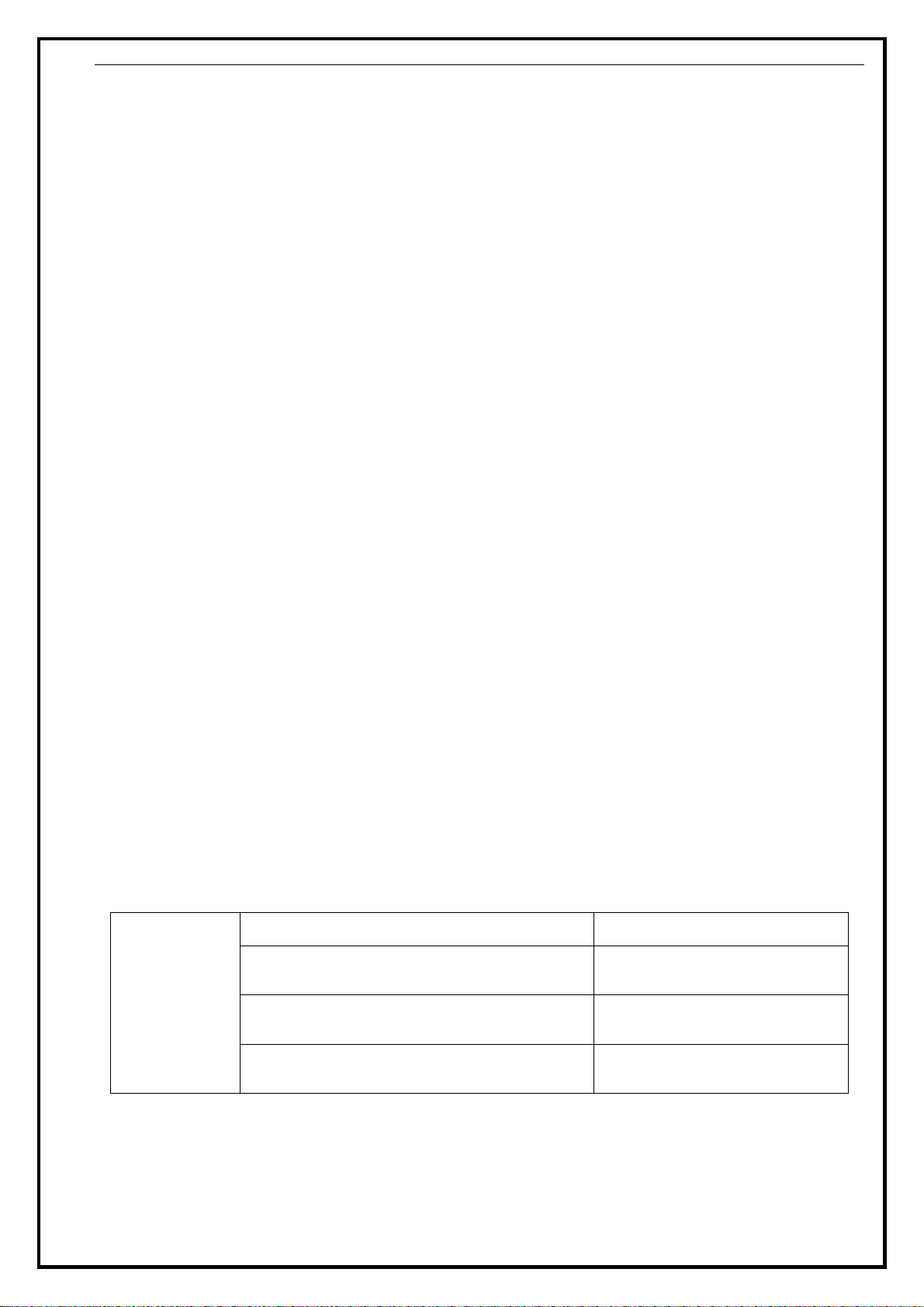
Trouble shooting table:
Note: In order to ensure the rise-fall control valve and the cylinder are reliable, the rise-fall
control valve should kept clean; the following instructions can be maintained.
The
Bead Breaker
shovel
operates
difficultly.
Jammed silencer Clean it or replace it.
The seal rings on the Bead Breaker
cylinder are broken. Replace it.
Leakage of Air network Check all the parts on
the air network.
The rise-fall control valve is broken. Replace it.

098D 201910
8
1. Disconnect the machine from electric power supply and pneumatic power supply,
dismount the two screw 11 in fig 4, remove the rise-fall control valve protect cover;
2. Dismount the two mufflers which are on the rise-fall control valve; (the A in fig 11)
3. Use the compressed air to clean the dirt on the muffler, if damaged, refer to the
exploded drawing and list to replaced it.(chapter 8)
A
Fi
g
11

098D 201910
9
7. Exploded drawing
F9850
F9851
F9852
F9853
F9854
F9855
F9856
F9857
F9814
F9858
F9859
F9859
F9861
F9860
F9813 F9815
F9823
F9804
F9806
F9831
F9807
F9829
F9830
F9832
F9833
F9827
F9813
F9805
F9827-1
F9827-2
F9827-3
F9827-4
F9827-5
F9827-6
F9827-7
F9827-5
F9827-8
F9827-9 F9827-10
F9827-9
F9827-11
F9827-12
F9827-13

098D 201910
10
F9804 CX-005-200000-0
Rise-fall switch base
plate F9858 C-098-020400-D Crash pad
F9805 B-017-040161-0
Cross flat head screw
M4*16 F9858 CX-098-020300-D Cushion connection seat
F9806 B-017-040301-0
Cross-round head screw
M4X30 F9858 B-004-120071-1
Hex nut(white)
M12*1.75*6
F9807 B-007-100121-0
Hex socket head bolt
M10*12 F9859 B-025-080101-0 Round head hex screw
F9813 S-012-010406-0
L-union 1/4-φ6 F9860 B-024-050101-1
Hex socket head bolt
M5*10
F9814 B-004-040001-1 Nut ( silver ) M4 F9861 B-004-060001-1 Nut M6
F9815 S-030-010818-0 Handle valve F9862 CX-098-020000-D 098D pressing arm(right)
F9823 C-007-181000-0
Control valve protection
cover F9827-1 C-098-070400-2 Help arm cylinder piston
rod
F9827 CW-105-209800-
2 Complete 098 cylinder F9827-2 C-098-070100-0 Help arm cylinder front
cover
F9829 CX-098-040000-0
Pressing roller bracket
support F9827-3 B-055-400002-0 Snap ring φ40
F9830 C-098-060100-0 Tire pressing roller 1 F9827-4 S-000-030265-0 O-seal φ30*2.65
F9831 B-055-300002-0 Snap ring Ø30(hole) F9827-5 C-098-070600-0 Cylinder washer Φ
31*50*15
F9832 CX-098-050000-0 Tire pressing roller shaft F9827-6 C-098-075400-0 009 help arm cylinder
piston Φ70
F9833 C-098-060200-0 Tire pressing roller 2 F9827-7 B-001-120001-0 Self-locking nut M12
F9850 CX-098-030000-0
Pressing arm pin (right) F9827-8 CX-009-070300-0 Help arm cylinder barrel
F9851 B-014-101301-0 Outer hex bolt M10*130 F9827-9 C-098-070500-0 Guide cover φ30*33*15
F9852 CX-098-110000-
D Mounting bracket seat -D F9827-10 S-000-063265-0 O-seal φ63*2.65
F9853 B-040-102020-1 Flat washerφ10 F9827-11 S-000-063355-0 O-sealφ63*3.55
F9854 B-001-100001-0 Locking nut M10 F9827-12 U-006-000001-0 Guide belt 4*2
F9855 CX-200-140000-0 Big washer F9827-13 CX-098-070200-0 Cylinder rear cover
F9856 B-001-160001-0 Self-locking nut M16
F9857 S-023-010801-6 Muffler 1/8
Table of contents