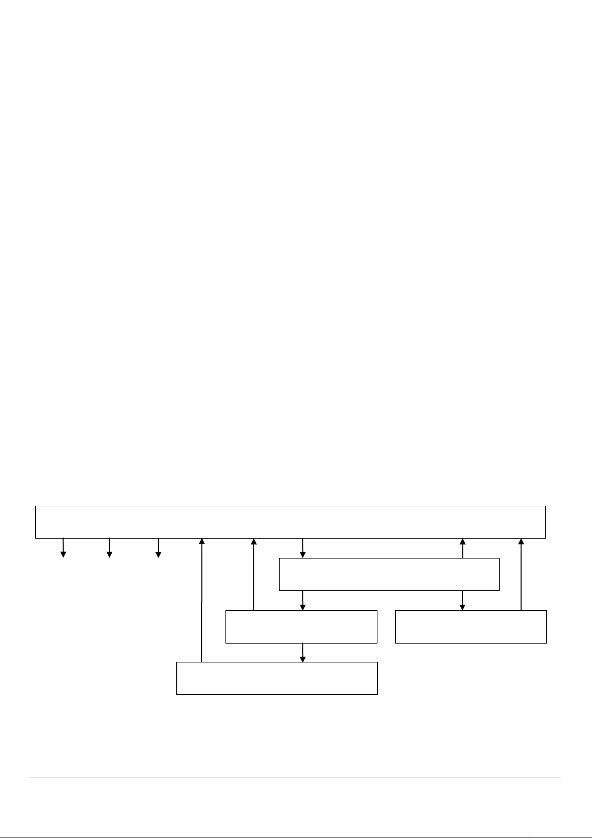
SmokeSight Option Card V0.1.0
1. If the existing alarm or alarms that you wish to remove are functional perform a ‘Return to Factory Defaults’ on
those alarms only. From Operation Mode this can be achieved by 4Tap, 5Tap, 5Tap of the Test+Hush button on
those alarms to be removed only.
2. Remove power to the existing alarm or alarms that you wish to remove from the network.
3. On any remaining smoke alarm select ‘Remove Slave Radio Node’. From ‘Operation Mode’ this can be achieved
by 4Tap, 1Tap, 2Tap, pause, 2Tap of the Test+Hush button. The network will then check to see which alarm
nodes are active and will remove any inactive alarm nodes from the network. This alarm only will remain in
‘Radio Interlink Configuration Mode’ as indicated by 3flash + 3beep every 10secs.
4. This smoke alarm will be placed into ‘Operation Mode’ 2mins after the last tap of the Test+Hush button or by
4Tap of the Test+Hush button. On any network alarm confirm that the built node count reported in ‘Operation
Mode’ agrees with your expected node count.
2.8.4 Delete Radio Network
This function deletes an existing radio interlink network.
1. Select ‘Delete Radio Network’ on any networked alarm. From ‘Operation Mode’ this can be achieved by 4Tap,
1Tap, 3Tap, pause, 3Tap of the Test+Hush button. The master node will then remove all alarm nodes, including
itself from the network. All alarms will remain in ‘Radio Interlink Configuration Mode’ as indicated by 3flash +
3beep every 10secs.
2. All smoke alarms will be placed into ‘Operation Mode’ 1hr after the last tap of the Test+Hush button or by 4Tap
of the Test+Hush button. On any network alarm confirm that the built node count reported in ‘Operation Mode’
agrees with your expected node count.
2.9 Auto Test
The Auto Test function provides scheduled, automatic testing of the smoke alarm. Testing consists of momentarily
simulating smoke internal to the smoke alarm which activates the smoke alarm’s siren. The option card listens for
the correct smoke alarm tone and reports an option card alarm if the test failed. The test establishes, on a regular
basis, that the smoke alarm’s smoke sensor, controller and siren are functional. Test duration is 5secs and can be
configured to be performed at a convenient time. The default time is 14days and 0hrs following insertion of the
option card batteries. The Auto Test establishes that only the local smoke alarm, on which the test is performed, is
functional. While interlinked alarms may also sound, Auto Test does not confirm operation of interlinked smoke
alarms. Access to Auto Test, Configuration Mode is only possible if the Auto Test switch is switched to ON.
2.9.1 Configuration
1. Switch on/Confirm that the Auto Test switch is set to ON. Refer to Enable Switches for details. The factory
default, test settings are every two weeks from the day and time that the option card is first supplied with
power. Continue with the following steps only if you wish to change Auto Test times.
2. Select ‘Auto Test Configuration Mode’ - From Operation Mode this can be achieved by 4Tap, 2Tap of the
Test+Hush button. Confirmation of this mode is reported by 4flash+4beep.
3. If you wish to alter the test ‘Frequency’ 1Tap, followed by 1Tap for every week, 2Tap for every two weeks, 3Tap
for every four weeks.
4. If you wish to alter the test day ‘Days from Now’ 2Tap, followed by 1Tap for tomorrow, 2Tap for two days time
up to 7Tap for the current day ie 0 days from now.
5. If you wish to alter the test hour ‘Hours from Now’ 3Tap, followed by 1Tap for 1 hour from now, 2Tap for two
hours from now up to 24Tap for the current hour ie 0 hours from now.
6. The smoke alarm will be placed into ‘Operation Mode’ 2mins after the last tap of the Test+Hush button or by
4Tap of the Test+Hush button. Confirm that the Auto Test Time from Now reported in ‘Operation Mode’ agrees
with your expected test time.