RedEarth SunRise SGS 1-PH AUTO User manual

SunRise Home Battery System
Model: SGS 1-PH AUTO with LG & BYD battery
Installation Manual

SunRise Manual - Version 2.3 SGS 1-PH AUTO – 29 Aug 2019
Safety instructions:
Physical specifications:
Weight: 107kg up to 227kg (no battery to max. of 5 batteries = 16.5kWh). Each battery weighs 24kg.
Dimensions:
104 cm H x 97 cm W x 54 cm D
Safety Instructions:
Physical Specifications:
WARNING: Installation and Maintenance of the Sunrise System should only be done by a
qualified Solar & Battery Electrician
WARNING: PV Arrays exposed to Sunlight will supply D.C Voltage to SunRise Battery System.
WARNING: Lithium Battery hazard

Overview:
The SunRise Home Battery is an Australian-made product that is designed to reduce your electricity bill. It does this
by storing your excess solar power for use at night.It can also provide backup power for your essential loads during
power outages.
SunRise is designed to be easy to install and can be located either inside or outside. It should be placed in a shaded
area. It can be placed on a 600x1200mm concrete base or be mounted on a wall on standard heavy-duty
airconditioner brackets. All Circuit breakers and DC Isolators are included within the system, so no isolators need to
be attached to the wall.
This manual describes the installation of the Model: SGS 1-PH AUTO of the SunRise System.
A 3-phase version of the SunRise is also available.
The SunRise system can be installed with or without batteries. Batteries can easily be added later, as demand grows
and budgets allow. Batteries must be of the same make and model.
•When installed with batteries excess PV solar electricity generated during the day will be used to reduce the
amount of electricity imported from the grid at night. In addition the battery ensures essential household
loads (fridges, lights etc) can be powered during a power outage. This uses an automatic transfer switch
included inside the SunRise unit.
•When installed without batteries excess PV generated during the day can be exported to the grid, which
reduces your electicity bill. Ensuring you have the best electricity plan from your provider will improve your
return.
•The SunRise system can also easily be retrofitted to an existing PV solar system.
The SunRise combines an AS4777.2 certified SunGrow 5kW inveter (SH5K-20) with the following battery options:
Up to 5 LG batteries (48Vdc Lithium-ion 6.5KWh/3.3kWh nominal each – Model EM048126P3/EM048063P3).
Up to 4 BYD Batteries (48Vdc Lithium-ion 2.56kWh nominal each – Model B – Plus Pro 2.5)
This Installation Guide should be read in conjuction with the following Sungow, LG & BYD User Manuals supplied
with the system.
Installation should conform to AS/NZS 3000 & AS/NZS 5033.
A total of 6.65kW of solar panels can be connected to the systems two
MPPT’s to claim full STCs (1.33 x 5.0kW). The maximum DC string
voltage is 600Vdc.
The SunRise SGS system can be remotely
monitored via SunGrow’s web portal or via
their their app (iSolarCloud app).
RedEarth Energy Storage can also provide a
remote monitoring service to ensure ongoing
operation of the SunRise battery system. Contact RedEarth Tech
Support on 0487 002 451.
Overview:

A typical complete installation of the SunRise Home Battery will require the electrical connection of the following
cables;
1. Install AC cables from the Main Switch Board (MSB) directly to the terminals inside the SunRise system (Grid
and EPS/Essential load supplies). Either a single 3Core + Earth cable or two 2C+E cables of sufficient diamter
for the distance can be used.
2. Install the supplied current monitor wire (from SunRise system to MSB) to monitor the grid feed-in level. A
standard Cat5/6 cable can be used.
3. Connection of up to 2 arrays of PV solar panels to the DC Isolator in the SunRise system. It is important to
connect the +ve and -ve cables of each string to the correct terminals in the DC Isolator (maximum of
6.65kW of panels and maximum PV string voltage of 600VDC)
4. Optional – Cat5E internet cable (to provide more reliable comms for remote monitoring) WiFi is included in
the system as default.
In addition, the installer will need to
program the Sungrow inverter for the
customer’s specific requirements (e.g.
level of grid-feed allowed by the utility)
Use either the Sungrow iSolarCloud APP
operating in local mode or via the
display panel on the front of the inverter
(remove the vent cover on the left side
of the SunRise to access the inverter’s
display panel)
Finally, the installer should connect the
SunRise to the customer’s internet if
remote monitoring is required. (see
OEM SunGrow documents included with
the SunRise system for additional details)
Note: The SunRise is not designed to act as the customers main switch board (MSB) as it does not include space for
additional main & customer circuit breakers or RCDs.

The following image shows the SunRise SGS 1-PH AUTO system with all components installed (including the
maximum 5 x 6.5kWh LG M48 batteries). The 2nd image shows the SunRise SGS without the batteries in place. Note:
The Sunrise is delivered with the inverter inside, but without the batteries inside the unit to allow the system to be
more easily transported and installed.
SunRise system overview:


The internal wiring layout is shown below.
The right side of the SunRise system includes the AC and DC Switch assemblies, the left side allows access to the
control panel of the inverter.

Details of the SunRise switch gear is shown below. The design of the SunRise includes all the Isolation in the
enclosure. If the inverter needs to be removed for repair, then the enclosure remains behind with the Isolation
intact. This is a similar approach to that adopted by Fronius with their solar inverters and removes the requirement
to add AC and DC Isolators on the wall next to the system.
The system is supplied without the batteries installed. This allows the enclosure to be more easily carried to difficult
installation locations. Once the system is in place the batteries are installed.
All connections are made with plugs except the AC connection from the Main Switch Board of the house, and the
two DC Solar strings connected to the built-in PV ARRAY DC ISOLATOR.

Following these steps will ensure you have a quick and easy install of the SunRise system:
1. Learn about the SunRise system and its options from RedEarth Energy Storage. (and read this manual)
2. Confirm the end-customers’ requirements, and which SunRise options are required. (for example, number of
batteries, backup option required, wall-mount?)
3. Transport, position and assemble the SunRise system. The SunRise can be installed on a concrete base or
mounted on heavy duty air-con brackets (available from RedEarth). The solar array is installed separately.
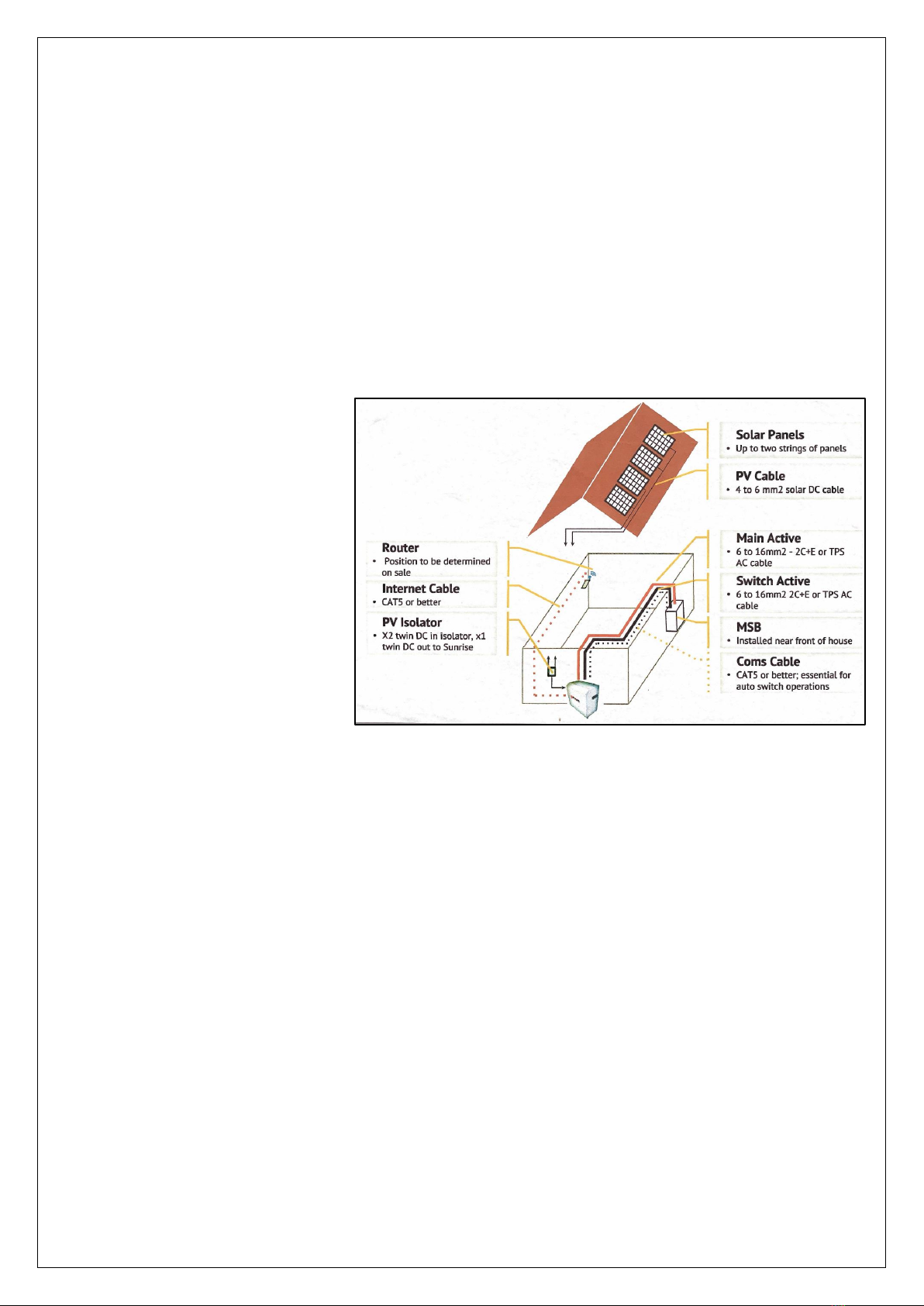
4. Wire the SunRise system to the Main Switch Board (MSB), including the grid feed CT monitor, and connect
the Solar arrays. If remote monitoring is required, then connect the internet (hard-wired or WiFi)
Back-up capability: To get the most benefit from the Back-up capability of the SunRise, the MSB loads should
be split into essential and non-essential loads. Appropriate MCBs, labels and a By-Pass switch are included in
the SunRise Parts kit.
5. Confirm the wiring is correct and then power-up the SunRise system. With your phone establish a link to the
on-board Wi-Fi of the Sungrow inverter. (see included Sungrow manual if required) and then program the
Sungrow to meet customer requirements (e.g. maximum feed-in Watts, maximum battery discharge SOC)
6. Setup remote monitoring: Program the Sungrow inverter to access the customer’s local Wi-Fi (if it is to be
used, otherwise connect the internet cable). Contact RedEarth during programming to confirm access for
remote monitoring of the SunRise system if required. (Tech support 0487 002 451)
7. Perform a customer induction (including system monitoring using the Sungrow app on their phone if
possible). Apply appropriate labels in/on MSB (see included SunRise Signage Overview document). Complete
a commissioning report as required by the CEC and clean-up the job site.
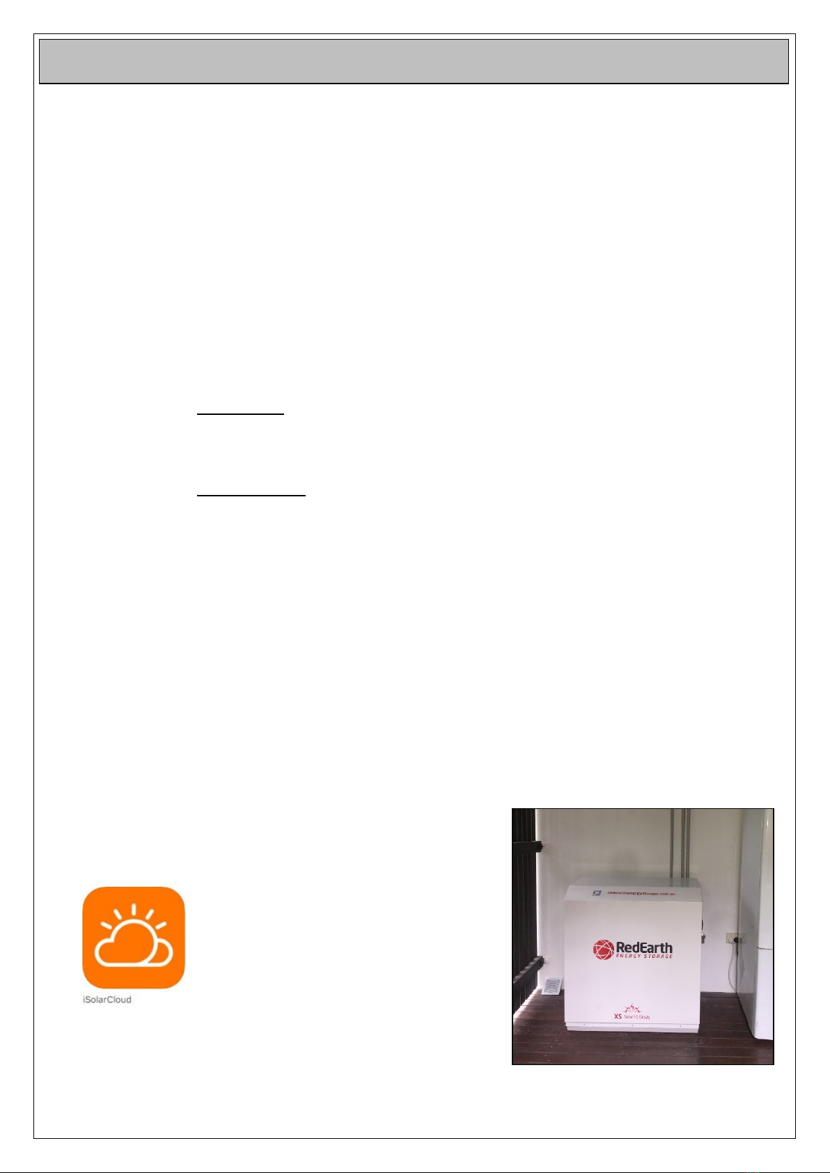
The SunRise system is designed to be easy to install. It is delivered without the
batteries installed to make it easier to install in difficult to reach areas.
A video showing the installation is available by scanning the image here. (scan the
image at right to view the video)
Additional support is available through video link/face time or by visiting the
RedEarth manufacturing facility in Brisbane, Australia. RedEarth’s Tech Support
number is +61 487 002 451.
RedEarth has additional material on its website, www.redearthenergystorage.com.au
For larger customers RedEarth also offers the option of onsite training either in your facility or on your jobsite.
Confirm details of the job:
•How much solar is required (a maximum of 6.65kW can be connected to the SunRise while still receiving all
the STC’s).
•Retro fitting to an existing solar system is easily done. There is no need to touch the existing PV system. The
CT from The SunRise system is placed on the incoming line to the house. In that way it also monitors what
the existing solar system is doing. This ensures that no more than the installer programmed feed-in, can
occur.
•How much battery is required? Up to 5x3.3kWh LG batteries can be installed (other battery options are
available from RedEarth including BYD and Troppo). If back-up power is more important, then more battery
should be installed. Additional batteries can be easily added later.
STEP 1: Learn about the SunRise System and its options:
STEP 2: Confirm job details and order the right SunRise options:
7 Steps to an easy install:

•If remote monitoring is required, is there internet available? Wi-Fi or hard-wire option? RedEarth can assist
with 3G/4G options if required.
•Confirm it is a single-phase house. Note that RedEarth has another version of the SunRise system for 3-phase
houses.
•Does the customer require back-up capability? If so, what is the condition of the MSB? Does it have space for
the additional 3 poles of switches for the backup system? Do you need to replace some of the existing 2-pole
RCDs with 1-pole RCBOs?
•Can the system be placed in a shaded area on or off the ground? How far is it from the MSB? What AC cable
size is required for the distance? RedEarth can provide cable. Remember that the essential loads are
permanently powered via the transfer switch inside the SunRise (if back-up capability is required)
•Is an optional remote earth fault alarm required, e.g. in the garage?
The SunRise System is delivered in individual boxes to allow for
easy installation on site.
The image at right shows a SunRise system being picked up at a
RedEarth facility in Brisbane.
Parts supplied with the SunRise system:
1. SunRise enclosure – pre-wired and factory tested with
the Sungrow inverter installed.
2. 1 box for each LG battery module supplied. These
include the correct communication cable as well as pre-
terminated DC battery cables of the correct length. Up to 5 LG battery modules can be installed (maximum
of 5 x 3.3 kWh batteries) Other battery options can be ordered including BYD and Troppo batteries.
3. 1 x Parts Kit containing all parts to complete the installation of the SunRise battery system in a normal
house.
4. 1 x set of manuals including OEM documents for the LG battery and Sungrow inverter.
5. Optional – Heavy duty wall-mounting bracket set.
6. Optional – 3-Core + Earth Orange Circ cable. To connect the SunRise to the Main Switch Board with only one
cable.
The SunRise system can be installed either indoors (e.g. in a shed) or outdoors. The system should be installed in a
shaded area. Note: If the system overheats it will shut down to protect itself.
Positioning of the SunRise system:
Stand-off from the floor, wall and ceiling/roof:
The SunRise System is to be installed at least 90mm off the wall to allow space for airflow from the vents and fans. It
is designed to be placed either on a concrete base/floor or mounted on 3 heavy duty air-con brackets above the
ground (max system weight 227kg). The mounting height of the base should not be > 50cm above the ground, to
allow positioning of the batteries and inverters during system assembly. At least 50cm clearance is required from the
top of the system to the roof/ceiling so that the cover can be removed, and cables checked.
•Distance from any heat source (e.g. hot water, air-con unit, gas heaters): >0.6m.
•Distance from any equipment including water taps >0.6m
•Clearance distances from windows and vents >0.6m.
•Do not block the rear vents by pushing the unit right up against a wall.
STEP 3: Transporting, positioning and assembling the Sunrise System:

•Do not block the air inlet by placing objects hard up against the sides of the system. Air enters through the
base of the system.
•Install in a shaded area outside direct sunlight.
1) Ground mount:
The SunRise can be bolted to the ground to prevent movement. Four
holes are provided, where dynabolts can be inserted. The holes
should be covered with 25mm caps (supplied) to maintain the IP43
rating of the system. (Note: prepare the wiring and conduit to pass
into the rear of the SunRise system prior to bolting it to the ground.
The image on the right shows the four holes for securing the system
to concrete, as well as one of the 25mm caps.
The image at left shows one of the holes
looking down from the top.
2) Wall mount:
The system can also be wall mounted using standard heavy-duty
airconditioning mounting bracket (available from RedEarth). These
images show a SunRise system installed on a wall. It is important
that the air-con brackets are correctly assembled to provide their full
rated strength. In addition the brackets themselves need to be
screwed to the wall; not just the supporting rail.
The SunRise system is
then bolted to the
three brackets using
the six bolts holes in
its base.
Airflow routing:
Air enters the SunRise system through four 300mm square vents. Air exits the system via four 125mm square
openings in the rear of the unit. These openings contain either a fan or a vent. In hotter climates up to 4 fans can be
installed. The fan operation is controlled by a thermal switch located near the top of the unit. This should be set to
activate the fans at 20-30 degrees.

LG battery cables KEEP SAME LENGTH (AS SUPPLIED BY Redearthng up the FPA3:
The diagram below shows an overview of the electrical connection inside the SunRise System.
STEP 4: Wiring up the Sunrise:

A typical complete installation of the SunRise will require the electrical connection of;
1. AC cables to the Main Switch Board (MSB) (Grid/Solar and Essential/EPS). If the Backup option is required
then the loads will need to be split in the MSB between essential and non-essential loads.
2. Install the CT current monitor in the MSB (use the supplied cable to power the CT monitor from the MSB).
Then install the 8 metre long CT current monitor comms cable from the MSB to the Sungrow inverter inside
the SunRise system. It can be extended if required.
3. Connect the PV array cables to the PV isolator inside the SunRise
4. Optional – Cat5E internet cable to the SunRise (otherwise use Wi-Fi)
Note: All isolators and MCBs are included in the Sunrise, so no wall-mounted isolators are required.
Note: The SunRise is not designed to act as the customers main switch board (MSB) as it does not include space for
additional main & customer circuit breakers or RCDs.
Follow the steps below to connect the SunRise battery system to the property.
1. Remove the aluminium lid of the SunRise enclosure by undoing the screws holding it in place, then lifting it
off. Note that the left side panel can also be removed to make it easier to install the Inverter.
2. The SunRise parts kit is inside sent the unit (see image below)
oTake the CT meter and install it in the MSB

3. Cable entry options: Pass all cables into and out of
the unit through the M25 penetrations that are
provided in the rear of the enclosure. The cable
glands provided in the Parts Kit allow standard
flexible conduit to be connected while maintaining
the IP rating of the enclosure. (Note: penetrations
can be made elsewhere in the enclosure, if more
appropriate) Use the provided cable glands or other
suitable glands to maintain the IP rating of the
system.
4. Connect the external cables;
oDecide if the optional wiring for the back-up
feature is required. If it is then in the MSB split
the loads into Essential and Non-essential:
This allows the Back-up feature to be used to
support selected essential loads during a
blackout. A maximum of 3kVA can be supplied
during back-up operation (5kVA during the
day, if PV is connected directly to the SunRise
system), however it is recommended to
connect far lower loads to the essential circuit
as the amount of energy available is limited to
the battery capacity (and the solar
contribution during the daytime) – The Parts
Kit contains a 25A 2-pole MCB to isolate the
Inverter (Grid/Solar) and Essential/EPS
circuits. In addition, a 63A Changeover switch
is included. This is a By-pass switch that
directly connects the Essential loads to the
Non-essential loads. It is only used if the
SunRise system is not operating, or not yet
installed. Labels are also included to use in
the MSB.
oConnect the AC cables of the Grid and
Essential supplies from the Main Switch
Board (MSB) directly to the terminals inside
the SunRise system (Grid/Solar and
EPS/Essential load supplies). A single 3-Core +
Earth cable of sufficient diamter for the
distance can be used (RedEarth can supply
this cable). Otherwise two 2C+E cables can be
used. In this case the two earths and neutrals
are connected to the Grid/Solar Earth and
Neutral terminals. Note that the essential
circuits are permanently supplied via the
transfer switch inside the SunRise system.
This means that twice the distance from the
MSB to the SunRise needs to used to
determine the cable size for the Essential load circuits.

oConnect the PV cables from the Solar arrays (if installed) to the MC4
Connectors coming out of the DC Isolator. They are postioned below the
Sungrow backup box labelled PV1 & PV2. The PV DC Isolator is hidden
behind a an enclosure to protect from accidential touch.
oThe current transducer CT cable (8 meters long) is already connected to
the SunGrow inverter. It needs to be routed from the SunRise system
back to the MSB.
oOptional internet cable can be connected from the home hub to the
inverter. Wi-Fi is available as standard. The inverter cover needs to be
removed to plug the internet cable in. The image at right shows where
to connect the cable, in position 3.
oOptional Remote Earth Fault Alarm
– Terminals are provided inside the
SunRise system that provide 230Vac
in the case of an Earth Fault. These
can be used to power an alarm in a
more frequented part of the home,
for example the garage. RedEarth
can supply a suitable alarm.
5. (a) Install the LG batteries.
oFirst connect the additional DC battery cables to the battery
bus bars (if extra batteries were ordered). These are provided
with the batteries. They are installed in the Bus bars provided
and shown at right.
oInstall the batteries with the battery terminals towards the
front of the unit: The batteries are lowered directly onto the
battery rails in the system. Position the Master battery (1st
battery) on the right of the system, away from the inverters.

oBMS communication cable from the
inverter to the Master battery. This cable is
already connected inside the Sungrow
inverter. The other end needs to be plugged
into the Master LG battery. Additional LG
batteries are then connected using the
inter-battery 10-pin lead provided with
each additional battery (black with yellow
ends). Note: 3.3 and 6.5kWh batteries
cannot be mixed.
oPlug the DC battery cables into the correct
terminals on the LG batteries. The battery is
now ready to be turned on.
5. (b) or Install the BYD batteries.
a. First connect the additional DC battery cables
to the battery bus bars (if extra batteries
were ordered). These are provided with the
batteries. They are installed in the Bus bars
provided and shown at right.
b. Install the batteries with the battery
terminals towards the front of the unit: The
batteries are lowered directly onto the
battery rails in the system. Position the
Master battery (1st battery) on the right of
the system, away from the inverters.
c. BMS communication cable from the BYD
BMU to the Master battery. This cable is
already connected inside the BMU. The other
end needs to be plugged into the Master BYD
battery. Additional batteries are then
connected using the inter-battery lead
provided with each additional battery.
d. Set the Red DIP Switch to number each
battery incrementally from 1 to 4.
e. Plug the DC battery cables into the correct
terminals on the batteries. The battery is now
ready to be turned on.
6. Once the wiring described above is completed the system is ready for Start-up.

Refer to the included OEM SunGrow manuals for additional details on the operation of each of the individual
components.
Pre-start-up Procedures:
With the lid removed confirm the following;
1. AC cables are connected into the inverter to the correct terminals of the terminal block.
2. The system is correctly earthed, either via the customer’s local earth or through a locally installed earth
stake.
3. The PV cables are connected to the DC Isolator, and the polarity is correct.
4. The battery terminal connections are correct. (if batteries are included in the system)
Start-up the battery in the SunRise system: (if batteries are included, otherwise skip this section)
LG Battery
1. Once cables are properly connected, ensure all breakers (AC and DC MCBs) are turned off.
2. Press and hold the power button on the Master LG battery (whichever has the blue communication cable
plugged into it. All other LG batteries will turn on. After less than a minute they will finish their start-up
procedure and indicate their current state-of-charge. The table below describes the lights that will be
shown on the LG batteries during start-up.
STEP 5: Starting up the Sunrise System:

3. After the LG battery has completed start-up, which takes < 1 minute, the indicators as shown below will be
on. For LG battery Trouble shooting refer to pp31 of the LG Installation manual which has been included
with your SunRise system.


BYD Battery
1. Press the Grey On/Off button to switch on the battery.
2. Green LED lights will indicate current SoC.
Start-up the Inverter of the SunRise system:
1. Reinstall the cover of the SunRise system.
2. Switch on the PV Array DC isolator on the right side of the system. The SunGrow inverter
will turn on if there is power from the PV panels.
3. Once the LG battery has completed its startup procedure, switch on the Main Battery DC
Isolator on the side of the system (if batteries are included).
4. The SunGrow inverter will establish communication with the battery.
5. Next program the SunGrow inverter, as required by the customer and utility. To do this you will need to
refer to the Sungrow manuals provided with the SunRise system.
oLocal Mode link: with your phone establish a link to the on-board Wi-Fi of the Sungrow inverter
using the iSolarCloud app. This requires you to connect to the Wi-Fi signal from the Sungrow
inverter. Find it in your Wi-Fi settings. Once you have done this go to Local Mode in the Sungrow
App and you will be linked to the inverter.
oNote: all the programming can also be done on the control
panel of the inverter itself if you do not want to connect via
your phone and Local Mode. To access the control panel
remove the vent on the left side of the system as shown
here.
oWork through the settings on the SunGrow App.
6. Turn on the AC MCBs and confirm the operation of the system,
including the operation of the EPS system (if batteries are included).
Note: the EPS system can support a maximum of 3000VA loads
during an outage, and so requires the loads in the MSB to be
appropriately split. Note also that if only one LG battery is included
then the EPS can only support 3000VA of loads during an outage. This
is the maximum power that a single LG battery can provide.
The system should now be fully operational. Check that all readings are as
expected. Refer to the trouble shooting guides in the included LG Chem and
Sungrow manuals if required.
•The SunRise is either hard-wired to the home internet or uses the customer’s Wi-Fi.
•If the customer’s WiFi is to be used, then the SunGrow inverter needs to be programmed to access it. This
will require the customer to provide their WiFi password. Refer to the included Sungrow manuals to setup
remote monitoring.
•If there is no internet available RedEarth can supply a 3G/4G dongle as an option.
Contact RedEarth once the system is online and the remote monitoring will be confirmed.
STEP 6: Setup remote monitoring:
This manual suits for next models
2
Table of contents