REDEKOP NH CR User manual

1
TM
NH CR
Removal Guide
for Installation of Redekop MAV Straw Chopper (SCU Ready)
CH0214-01_R0 Feb_2022
Redekop Manufacturing 2014
Saskatoon SK Canada S7K 3J7
Ph: 1.306.931.6664
1.866.REDEKOP (1.866.733.3567)
Email: [email protected]
Web: www.redekopmfg.com

2
NH CR
Factory Component Removal Guide for
Installation of Redekop MAV Straw Chopper
Table of Contents
Section
Safety 0
Drive Shield Removal 1
Disconnect Wire Harness 2
Fuel Tank Support Removal 3
Drive Belt Removal 4
Rear Upper Roof Panel Removal 5
Chopper Removal 6
Spreader Removal 7
Draper/Conveyor Removal 8
Draper Hydraulic Motor Removal 9
Jackshaft Removal 10
Upper Drive Sheave Removal 11
Seed Loss Monitor Panel Removal 12

3
1. Left Rear Access Panel
2. Drive Shield
3. Wire Harness
4. Fuel Tank
5. Drive Belt
6. Rear Upper Roof Panel
7. Chopper
8. Spreader
9. Draper/Conveyor
10. Jackshaft
11. Upper Drive Sheave
12. Seed Loss Monitor Panel
NH CR
Factory Component Removal Guide for
Installation of Redekop MAV Straw Chopper
Component Reference
12
3
4
5
6
7
8
9
11
12
5
10

4
Supplies required to assist during the removal procedure:
Blocking
- 10 x 8 x 43 inches / 250 x 200 x 1100 mm
- required for section 0.13.2
Pallet
- 40 x 70 inches /1000 x 1800 mm
- required for section 4.3
Locking Mechanism
- required for section 3
Gear Puller
- required for section 2.4
Requirements:

5
0 Safety
0.1 Instructions
0.1.1 IMPORTANT: Read through this instruction
manual thoroughly and familiarize yourself with the
machine before removing these components. Do not skip
steps or perform them out of order.
This instruction manual explains the proper procedure
for preparing the combine and removing the Factory
Components in order to install the Redekop MAV
Chopper.
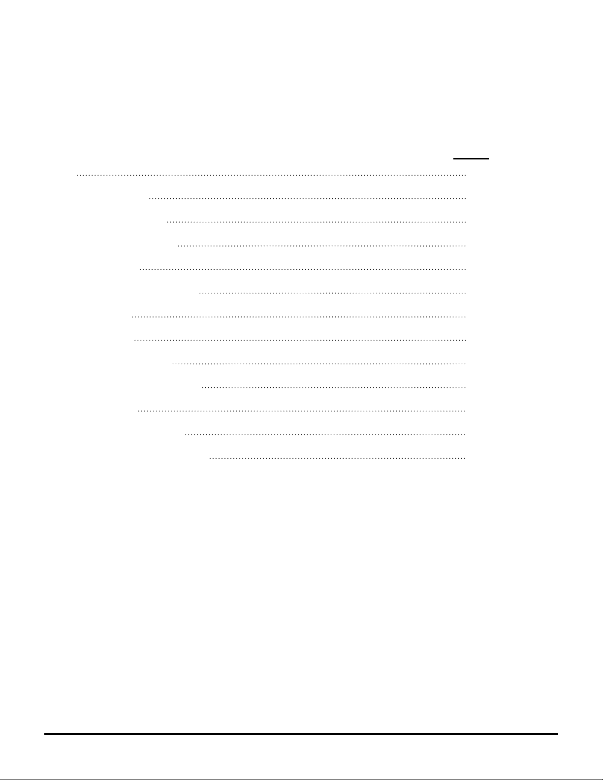
0.2 Recognize Safety Information
0.2.1 This is a safety-alert symbol. When you see this
symbol on your straw chopper or in this manual, be alert
to the potential for personal injury.
Follow recommended precautions and safe operating
practices.
0.3 Understand Signal Words
0.3.1 A signal word - DANGER, WARNING, or
CAUTION - is used with the safety-alert symbol.
DANGER identies the most serious hazards.
WARNING or CAUTION safety signs are located near
specic hazards or precautionary areas in this manual.
0.4 Follow Safety Instructions
0.4.1 Carefully read all safety messages in this manual
and on your machine. Keep safety signs in good
condition. Replace missing or damaged safety signs. Be
sure new equipment components and repair parts include
the current safety signs. Replacement safety signs are
available from your dealer.
There can be additional safety information contained on
parts and components sourced from suppliers that is not
reproduced in this manual.
Learn how to operate the machine and how to use
controls properly. Do not let anyone operate without
instruction.
Keep your machine in proper working condition.
Unauthorized modications to the machine may impair
the function and/or safety and aect the machine’s life.
If you do not understand any part of this manual and
need assistance, contact your dealer.

6
0.7 Remove Key from Ignition
0.7.1 ALWAYS shut o combine engine prior to working
on it.
Apply park brake, remove key and lock operators cab.
If the combine is equipped with an additional safety
master power switch, turn this to the Power OFF position.
0.5 Safe Operating Practices
0.5.1 DO NOT stand near combine when machine is
running.
ALWAYS refer to your Combine Operator’s Manual and
review the Safety section before operating machine.
The Combine Operator’s Manual details safe operating
practices that must be followed to protect you and others
from accidental injury and/or death.
Operate machine only when all guards are correctly
installed.
Before moving away, always check immediate vicinity of
machine (e.g. for children). Ensure adequate visibility.
Use a horn as a warning immediately before moving
away.
When making turns, always take into consideration the
width of the attachment and the fact that the rear end
of the machine swings out. Attachments and ground
conditions aect the driving characteristics of the
combine.
Never leave combine unattended as long as engine is
running.
0.6 Work In Ventilated Area
0.6.1 Engine exhaust fumes can cause sickness or
death. If it is necessary to run an engine in an enclosed
area, remove the exhaust fumes from the area with an
exhaust pipe extension.
If you do not have an exhaust pipe extension, open the
doors and get outside air into the area.

7
0.9 Practice Safe Maintenance
0.9.1 Understand service procedure before doing work.
Keep area clean and dry.
Never lubricate, service, or adjust machine while it is
moving. Keep hands, feet and clothing away from power-
driven parts. Disengage all power and operate controls
to relieve pressure. Lower equipment to the ground. Stop
the engine. Remove the key. Allow machine to cool.
Securely support any machine elements that must be
raised for service work.
Keep all parts in good condition and properly installed.
Fix damage immediately. Replace worn or broken parts.
Remove any buildup of grease, oil or debris.
On self-propelled equipment, disconnect battery ground
cable (-) before making adjustments on electrical systems
or welding on machine.
0.8 Block Wheels
0.8.1 Park the combine on level ground.
Always engage the park brake and block the combine
wheels prior to working to prevent the combine from
moving.
0.11 Avoid Contact With Moving Parts
0.11.1 Keep hands, feet and clothing away from power
driven parts. Never clean, lubricate or adjust machine
when it is running.
0.10 Guards and Shields
0.10.1 Keep guards and shields in place at all times.
Ensure that they are serviceable and maintained
correctly.

8
0.12 Avoid High-Pressure Fluids
0.12.1 Inspect hydraulic hoses periodically – at least
once per year – for leakage, kinking, cuts, cracks,
abrasion, blisters, corrosion, exposed wire braid or any
other signs of wear or damage.
Replace worn or damaged hose assemblies immediately.
Escaping uid under pressure can penetrate the skin
causing serious injury.
Avoid the hazard by relieving pressure before
disconnecting hydraulic or other lines. Tighten all
connections before applying pressure.
Search for leaks with a piece of cardboard. Protect hands
and body from high-pressure uids.
If an accident occurs, see a doctor immediately. Any uid
injected into the skin must be surgically removed within
a few hours or gangrene may result. Doctors unfamiliar
with this type of injury should reference a knowledgeable
medical source.
0.13 Dispose of Waste Properly
0.13.1 Improperly disposing of waste can threaten the
environment and ecology. Potentially harmful waste
includes such items as oil, fuel, coolant, brake uid, lters
and batteries.
Use leakproof containers when draining uids. Do not
use food or beverage containers that may mislead
someone into drinking from them.
Do not pour waste onto the ground, down a drain or into
any water source.
0.14 Use Proper Lifting Equipment
0.14.1 Lifting heavy components incorrectly can cause
severe injury or machine damage.
Follow recommended procedure for removal and
installation of components in the manual.
Ensure lifting equipment is rated for the job
Ensure operator is appropriately licensed to operate
lifting equipment

9
0.16 Sound Level
0.16.1 This product produces sound pressure levels in
excess of 90 dB within 10m of discharge area.
Hearing protection is required!
Interference with speech communication, acoustic signals
is possible.
0.15 Personal Protective Equipment (PPE)
0.15.1 A Qualied Person designated by the employer,
who is knowledgeable about and familiar with all
relevant specications and assembly instructions and
is capable of identifying existing or potential hazards
in surroundings or working conditions which may be
hazardous or dangerous to employees shall determine
appropriate Personal Protective Equipment required for
this assembly.
Personal Protective Equipment (PPE) are devices worn
by the employees to protect against hazards in the
environment. Examples include safety glasses, face
shields, respirators, gloves, hard hats, steel-toe shoes,
and hearing protection. Wear close tting clothing and
safety equipment appropriate for the job.
Operating equipment safely requires the full attention of
the operator. Do not wear radio or music headphones
while operating machine.
0.17 Prepare for Emergencies
0.17.1 Be prepared if a re starts.
Keep a rst aid kit and re extinguisher handy.
Keep emergency numbers for doctors, ambulance
service, hospital and re department near your
telephone.

10
0.19 Remove Accumulated Crop Debris
0.19.1 The build up of cha and crop debris in the
engine compartment, on the engine, and near moving
parts is a re hazard. Check and clean these areas
frequently.
0.20 In the Event of Fire
0.20.1 Stop work immediately at rst sign of re. This
may be the smell of smoke or the sight of smoke or
ames.
If a re can be safely extinguished, proceed carefully and
follow these guidlines:
1. Remove re extinguisher from bracket and carry it to
the area of re.
2. Approach area of re wind to your back.
3. Pull the safety pin out of actuating lever.
4. Hold extinguisher upright and aim hose at base of
ames.
5. Squeeze lever to discharge re extinguisher.
6. Move hose to cover the source of the re evenly with
extinguishing agent.
CAUTION: Do not risk personal injurty. If a
re is too far advanced, do not try to extinguish it.
0.18 Fire Extinguisher
0.18.1 A 6 kg (15 lb) general-purpose re extinguisher
meeting national certication requirements must be
installed on left side of operator’s platform.
Maintain re extinguisher to keep it in operating condition.
Make sure that the re extinguisher is always ready for
use. Refer to the re extingisher’s manual for instructions
on how to operate it. Once extinguisher is operated - no
matter how long - it must be recharged.
Keep the engine clean and free of dust, cha and straw
to prevent the possibility of re.

11
1.1 Lift up the left side access panel (A)
1 Drive Shield Removal
C
C
B1
A
1.2 Remove drive shield (C)
B
1.1.1 Turn Master Power O (B)

12
2.2 Disconnect wire harness (C) from right rear light (C1)
- cut nylon cable ties that tie harness to chopper
2.3 Disconnect wire harness (D) from sensors x3
- cut nylon cable ties that tie harness to chopper
2.4 Tie harness up out of the way
C1 C
D
D
D
2 Disconnect Wire Harnesses
2.1 Disconnect wire harness (B) from left rear light (B1)
- cut nylon cable ties
B
B1
3 Fuel Tank Support Removal
3.1 Drain fuel from rear fuel tank at side fuel
tank valve (A) into clean container(s)
- to decrease the weight to be supported by the
strapping in next steps
- fuel to be relled into fuel tank at completion
A

13
3.2 Remove rear glamour panel (B)
B
3.3 Secure rear fuel tank (D)
3.3.1 Run a ratchet strap (E) x2 around the rear fuel tank
bottom support bracket (C) on each end and secure to the
auger bracket (F) and handrail (G)
3.3.2 Secure a ratchet strap (E) to the rear fuel tank
bottom support bracket (C) near the middle and secure to
the handrail
3.3.2 Tighten straps (E& F)
CD
E
E
E
D
3.2 Remove side mounting hardware (C1) x4 mounting
fuel tank support (C) to chopper
- both sides
- to be reinstalled after the new chopper is installed
C
C1
F
G

14
4 Drive Belt Removal
Procedure required only if SCU is being installed
Do NOT remove drive belt if SCU is NOT being
installed
4.1 Loosen belt tensioner (A) on jackshaft (B)
4.1.1 Rotate tension link pivot (A1) clockwise
A1 B
C
A
4.2 Remove drive belt (C)
A1
A
C
C
B

15
5 Rear Upper Roof Panel Removal
5.1 Remove side mounting hardware (A1) x3
- both sides
5.2 Remove top mounting hardware (A2) x5
5.3 Remove rear upper roof panel (A)A
A1
A2
A
6 Chopper Removal
This component weighs
500 lbs / 230 kg
Use a forklift with appropriate
capacity
6.1 Remove top front sidewall mounting bolt (A1) x1
- both sides
A1
A1

16
B1
B
B
6.2 Loosen belt tension rod (B1) for belt tensioner (B2) for
combine drive belt (B) to jackshaft (C)
6.2.1 Remove combine drive belt (B) from jackshaft (C)
C
B2
6.3 Raise a pallet (D) with extra blocking (D1)
underneath the chopper (A) to hold the chopper in place
when all supports are removed.
- secure rear end of chopper down, for the
chopper is front heavy and will lean forward
D1
D
A
6.4 Remove bottom mounting bolts (E1) x2 mounting
jackshaft (E) to support plate (F)
E1
E
F

17
6.6 Remove mounting hardware (F1) x3 mounting
suppport plate (F) to combine
- may have to loosen hardware (F2) on inside of combine
- both sides
F
F
F1
F
F2
6.5 Remove chopper mounting hardware (A2) x4 from
combine wall
- both sides
A2
6.7 Remove chopper (A) from combine
A

18
7 Spreader Removal
7.1 Disconnect hydraulic hoses (A) at quickcouplers
running from spreader (C) to hydraulic block
- slide hoses out of sleeve (A1)
7.2 Disconnect electrical connector (B)
A
A1
A
B
AB
7.3 Ensure spreader (C) is horizontal
7.3.1 Lay hydraulic hoses and electrical harness on top
of spreader (C)
C
C
7.4 Provide blocking (D) below spreader (C) for support
upon removal
C
7.5 Remove mounting hardware (C1) x2 mounting
spreader arms to rear of combine
- both sides
C
C1
D

19
8 Draper/Conveyor Removal
8.1 Disconnect and remove sensor (B) for draper/
conveyor (A)
B
A
B
8.2 Remove hydraulic motor and mounting bracket (C)
mounted to outer left side of combine
C

20
CG
9.1 Remove draper hyd motor (K) from combine
K
K1
K2
K3
H
Parts List:
HH147 Hyd. Hose .5 x 24L (C) Qty 1
H14-06F Fit Hyd Cap 6 FORS (G) Qty 1
9 Draper Hydraulic Motor Removal
Table of contents
Other REDEKOP Food Processor manuals