RedHotDot HOT MIG-19 User manual

HOTMIGMIG‐19–MIG‐27–MIG‐29
FR NOTICE D’UTILISATION………...6
EN USER’S MANUAL…………………11
DE BETRIEBSANLEITUNG………….16
ES MANUAL DEL USUARIO………...21

HOTMIGMIG‐19–MIG‐27–MIG‐29
I – MIG-19 / MIG-27
13 6
7 3
12
2
11
1
5
4
9 8
10
II – MIG-29
Fig 2-B :
13
6
3
5
12
16 15 1
10
4
15
7 2
11
4
Fig 2-C : 9
8
III
AB

HOTMIGMIG‐19–MIG‐27–MIG‐29
IV
V
VI

HOTMIGMIG‐19–MIG‐27–MIG‐29
VII
1
MIG-29
2
•Prémonter les vis
manuellement sans les bloquer
•Pre-install the screws
manually without blocking them
Vis/Screws
M5x12 (x8)
Ecrous/Nuts
M5x8 (x8)
MIG-19 – MIG-27 – MIG-29
3
Visser toutes les vis du support bouteilles
Tighten all the screws of the gas bottle stand
4

HOTMIGMIG‐19–MIG‐27–MIG‐29
M5x12 (x4)
56
MIG-29 (option ref. 032880 / 038897 / 032958 / 032972 )

HOTMIGMIG‐19–MIG‐27–MIG‐29FR
DESCRIPTION
Merci de votre choix ! Afin de tirer le maximum de satisfaction de votre poste, veuillez lire avec attention ce qui suit : Les
MIG-19, MIG-27 et MIG-29 sont des postes de soudure semi-automatique « synergic » sur roues, ventilés pour le soudage
(MIG ou MAG). Ils sont recommandés pour le soudage des aciers, des inox, des alu-miniums et pour le soudo brasage des
aciers haute résistance avec les fils CuSi et CuAl (idéal en réparation carrosserie). Leur réglage est simple et rapide grâce à
la fonction « vitesse de fil synergique ». Les T1 et MIG-29 fonctionnent sur une alimentation 400V triphasée. Le MIG-19 /
MIG-27 fonctionnent en 230V monophasées.
ALIMENTATION ÉLECTRIQUE
Le courant effectif absorbé (I1eff) pour les conditions d’utilisation maximales est indiqué sur l’appareil. Vérifier que
l’alimentation et ses protections (fusible et/ou disjoncteur) sont compatibles avec le courant nécessaire en utilisation.
L’appareil doit être placé de façon telle que la fiche de prise de courant soit accessible.
-Ces appareils sont livrés avec une prise 16A de type Rs-015 CEE.
-Les MIG-19 / MIG-27 doivent être reliés à une prise 230V 1PH AVEC terre protégée par un disjoncteur 16A retardé et
différentiel 30mA.
-Les MIG-27, MIG-29 doivent être relié à une prise 400V 3ph AVEC terre protégée par un disjoncteur 16A retardé et
différentiel 30mA. Ne pas utiliser de rallonge ayant une section inférieure à 2,5 mm².
DESCRIPTION DU POSTE (FIG 1 & 2)
1- Interrupteur marche arrêt
2- Réglage de puissance par un commutateur 7 positions
suivant le poste : permet d’ajuster la tension de soudage
en sortie de générateur. Le réglage de tension de sortie
est proportionnel à l’épaisseur du matériau à souder.
(fig. 6)
3- Clavier de réglages des paramètres de soudage
(mode manuel ou automatique).
4- Raccords torche au standard européen.
5- Connecteur de commande du spool gun.
6- Support torches avant.
7- Câble d’alimentation (2m MIG-19, 3m MIG-27,
6m MIG-29).
8- Sortie pince de masse pour les MIG-19 / MIG-27, câble
de masse avec pince 200A pour le MIG-29.
9- Support bouteilles (maxi 1 bouteille 4m³ pour
le MIG-19 et maxi 2 bouteilles de 4m³ pour les
MIG-27, MIG-29).
10- Chaine de fixation pour bouteille. Attention :
bien fixer la bouteille !
11- Support bobine Ø 200/300 mm.
12- Electrovanne torche 1.
13- Support de câble torche arrière.
Pour les MIG-29:
14- Support bobine Ø 200mm.
15- Electrovanne torche 2.
16- Electrovanne torche spool gun

HOTMIGMIG‐19–MIG‐27–MIG‐29FR
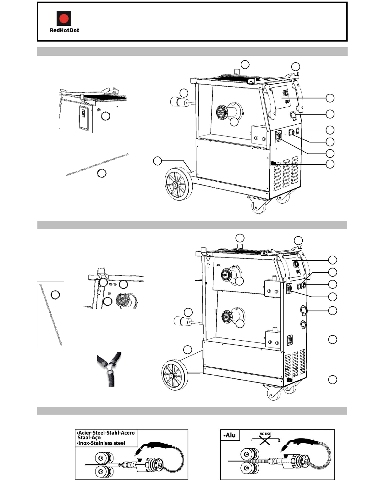
SOUDAGE SEMI-AUTOMATIQUE EN ACIER/INOX (MODE MAG) (FIG 3)
Ces appareils peuvent souder du fil acier et inox de 0,6/0,8 et 1. (fig 3A) L’appareil est livré d’origine pour fonctionner
avec du fil Ø0,8 mm en acier. Lorsque vous utilisez du fil de diamètre 0,6 mm ; il convient de changer le tube contact.
Le galet du moto-dévidoir est un galet réversible 0,6 / 0,8mm. Dans ce cas, le positionner de telle façon à lire 0,6 mm
sur le flanc visible du galet. L’utilisation en acier ou inox nécessite un gaz spécifique au soudage argon + CO2 (Ar +
CO2). La proportion de CO2 varie selon l’utilisation. Pour le choix du gaz, demander conseil à un distributeur de gaz.
Le débit de gaz en acier se situe entre 8 et 12 L/min selon l’environnement et l’expérience du soudeur.
SOUDAGE SEMI-AUTOMATIQUE ALUMINIUM (FIG 3)
Ces appareils peuvent souder du fil aluminium de 0,8 et 1 mm. (fig 3B).
Pour souder l’aluminium, il faut utiliser un gaz neutre: argon pur (Ar). Pour le choix du gaz, demander conseil à un
distributeur de gaz. Le débit du gaz se situe entre 15 et 25 L/min selon l’environnement et l’expérience du soudeur.
Ci-dessous les différences entre l’utilisation soudage acier et soudage aluminium :
-La pression des galets presseurs du moto-dévidoir sur le fil : mettre un minimum de pression afin de ne pas écraser
le fil.
-Tube capillaire : retirer le tube capillaire avant de connecter la torche aluminium avec une gaine en téflon.
-Torche : utiliser une torche spéciale aluminium. Cette torche possède une gaine téflon afin de réduire les
frottements.
-NE PAS couper la Gaine au bord du raccord !! cette gaine sert à guider le fil à partir des galets. (figure 3-B)
-Tube contact : utiliser un tube contact SPECIAL aluminium correspondant au diamètre du fil.
SOUDAGE SEMI-AUTOMATIQUE DES ACIERS À HAUTE LIMITE ÉLASTIQUE
Ces appareils sont recommandés par les fabricants d’automobiles pour soudobraser les tôles à haute limite élastique
avec un fil en cuprosilicium CusI3 ou cuproaluminium CuAl8 (Ø 0,8mm et Ø 1mm). Le soudeur doit utiliser un gaz
neutre: argon pur (Ar). Pour le choix du gaz, demander conseil à un distributeur de gaz. Le débit du gaz se situe entre
15 et 25 L/min.
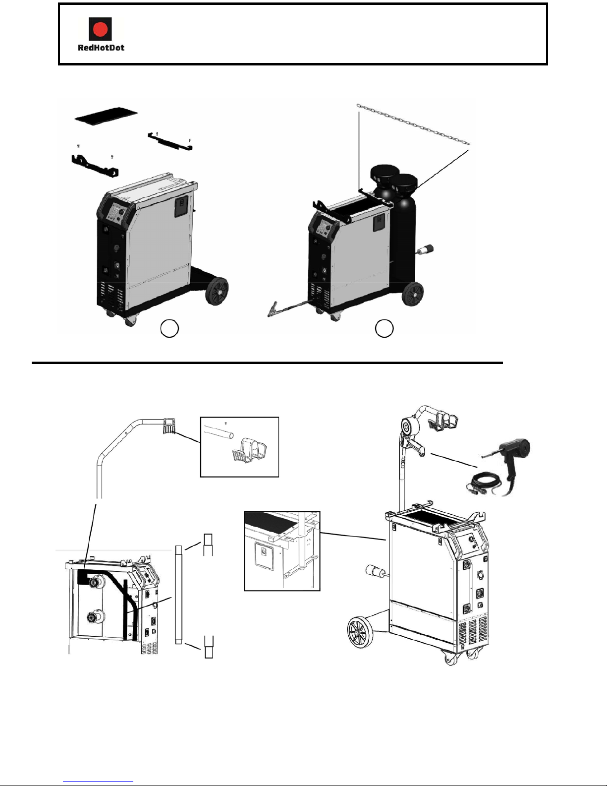
RACCORDEMENT GAZ (FIG 2)
Visser le mano-détendeur sur la bouteille de gaz (le manodétenteur n’est pas livré avec
le poste). Pour une utilisation avec une ou deux bouteilles de gaz.
Pour relier 2 bouteilles de gaz aux 3 torches, il faut couper le tuyau en 3 et connecter 1 Y. (fig 2C)
Pour relier une seule bouteille de gaz aux 3 torches, il faut couper le tuyau en 4 et connecter 2 Y.
Connecter chaque bouteille sur les électrovannes en respectant l’ordre :
- électrovanne T1 en haut à gauche (fig 2B:13)
- électrovanne Spool gun en haut à droite (fig 2B:17)
- électrovanne T3 en bas. (fig 2B:16) Pour éviter toute fuite de gaz, utiliser les colliers livrés avec l’appareil.
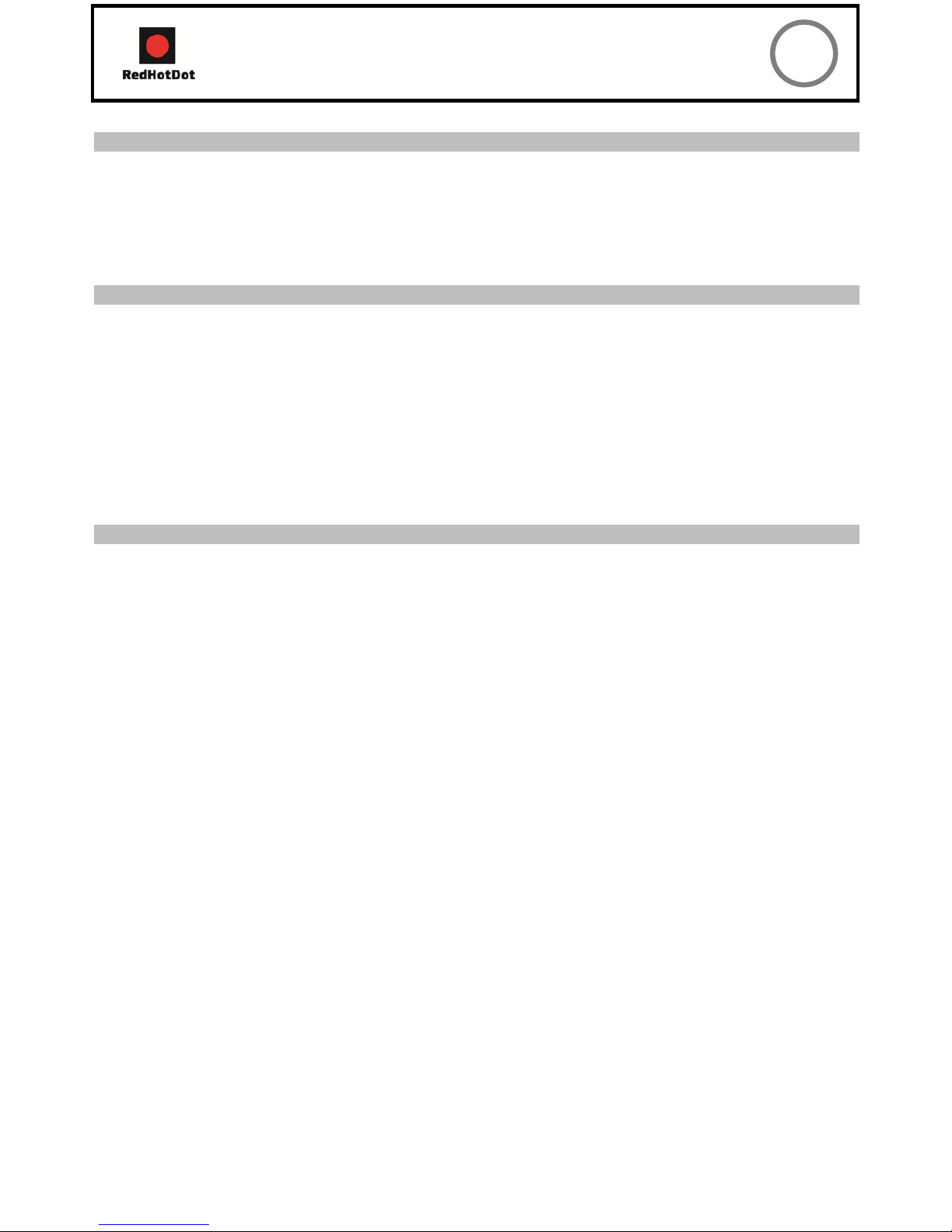
PROCÉDURE DE MONTAGE DES BOBINES ET DES TORCHES (FIG 4)
-Ouvrir la trappe du poste.
-Positionner la bobine en tenant compte de l’ergot d’entrainement (fig 4:2) du support bobine.
-Régler le frein de la bobine (fig 4:3) pour éviter lors de l’arrêt de la soudure que l’inertie de la bobine n’emmêle le fil.
De manière générale, ne pas serrer trop fort !
-Les galets moteur (fig 4:4) sont des galets double gorge (0,6/ 0,8 et 0,8/ 1). L’indication qu’on lit sur le galet est
celle que l’on utilise. Pour un fil 0,8 mm, utiliser la gorge de 0,8.
-Pour la première mise en service :
-Desserrer la vis de fixation du guide fil (fig 4:6)
-Pour régler la molette des galets presseurs (fig 4:5), procéder comme suit :
-Desserrer au maximum, actionner le moteur en appuyant sur la gâchette de la torche, serrer la molette tout en res-
tant appuyé sur la gâchette. Plier le fil en sortie de la buse. Mettre un doigt sur le fil plié pour l’empêcher d’avancer.
Le réglage du serrage est bon lorsque les galets patinent sur le fil même si le fil est bloqué en bout de torche.
-Choisir le diamètre du tube contact au bout de la torche. Utiliser un tube contact adapté au diamètre du fil utilisé. Le
réglage courant: la molette des galets (fig 4:5) sur graduation 3 pour l’acier et 2 pour l’aluminium.Nb: pour le fil
aluminium mettre un minimum de pression afin de ne pas écraser le fil.

HOTMIGMIG‐19–MIG‐27–MIG‐29FR
CHOIX DES BOBINES
Configurations possibles:
type fil
Torche 1 Torche 2
Spool gun
Gaz
MIG-19,
MIG-27,
MIG-29 NIG-29
MIG-19,
MIG-27,
MIG-29
Ø300
x
acier Ø200
x x
argon
Ø100 x +
CO2
inox
Ø200
x x
Ø100 x
CuSi3
Ø200
x x
CuAl8 Ø200
x x
Alu Ø300 x* argon
AlMg5
Ø200 x*
x*
pur
AlSi5
Ø100 x
AlSi12
Ø100 x
CuSi3:préconisation OPEL et Mercedes
CuAl8:préconisation Peugeot/Citroën/Renault
AlSi12:préconisation pour l’aluminium automobile à partir de tôle d’épaisseur comprise entre 0,6 et 1,5 mm
*prévoir gaine téflon/tube contact spécial
alu Ôter le tube capilaire
CLAVIER DE COMMANDE (FIG 5)
1- Choix du mode de soudage: -
NORMAL(2T) : soudage standard 2 temps
-DELAY : fonction «point de chainette», avec réglage
du diamètre de l’intermittence de point
-SPOT : fonction bouchonnage/spot, avec réglage
du diamètre du point.
2- Réglage de la vitesse :
Potentiomètre d’ajustage de la vitesse du fil. La vitesse
varie de 1 à 15m/minute.
3- Potentiomètre de réglage SPOT/DELAY.
4- Mode Manual :
En mode manuel, la vitesse de dévidage du fil est déter-
minée par l’utilisateur en ajustant le potentiomètre (2).
MODE "MANUAL" (FIG 5)
5- Mode Synergic :
Positionner le potentiomètre (2) au milieu de la zone
«OPTIMALE SYNERGIQUE».
Dans ce mode le poste détermine la vitesse de fil
opti-male à partir de 3 paramètres :
-Tension -
Diamètre de fil
-Nature du fil Il est possible d’ajuster la vitesse du fil
+/-En position Normal (2T), 2 modes sont proposés
pour faciliter le réglage du poste: Manual ou Synergic.
6- Voyant de protection thermique sur le clavier de
com-mande : signale une coupure thermique lorsque
l’appa-reil est utilisé de façon intensive (coupure de
plusieurs minutes).
Pour régler votre poste procéder comme suit:
-Choisissez la tension de soudage à l’aide du commutateur 7 positions
exemple: position 1 pour de la tôle de 0,6 mm et position 7 pour de la tôle de 4
mm -Ajustez la vitesse du fil à l’aide du potentiomètre (2)
conseil:
L’ajustement de la vitesse du fil se fait souvent «au bruit»: l’arc doit être stable et avoir très peu de
crépitement. Si la vitesse est trop faible, l’arc n’est pas continu.
Si la vitesse est trop élevée, l’arc crépite et le fil a tendance à repousser la torche.

HOTMIGMIG‐19–MIG‐27–MIG‐29FR
MODE "SYNERGIC" (FIG 5)
Grâce à cette fonction, plus besoin de régler la vitesse du fil.
Pour cela:
-Positionner le potentiomètre (2) vitesse de fil au milieu de la zone «Optimal Synergic»
-Sélectionner:
-La nature du fil (5)
-Le diamètre du fil (5)
-La puissance (commutateur 7 positions en face avant) Pour sélectionner la position adéquate en fonction de l’épais-
seur à souder se référer au tableau (fig-6)
A partir de cette combinaison de paramètres, l’appareil détermine la vitesse de fil optimale et le poste est prêt à sou-
der.
Il est ensuite possible d’ajuster la vitesse du fil si nécessaire + ou - grâce au potentiomètre (2).
Pour chaque torche , mémorisation des dernières configurations de soudage est effectuée (diamètre du fil, nature du
fil, mode).
Choix du GAZ (uniquement pour le soudage acier):
En mode synergique, le poste détermine les paramètres de soudage en fonction du gaz utilisé. Par défaut, en sou-
dage acier, le poste est configuré «argon+CO2».
Pour changer de gaz et configurer le poste en mode CO2 ou revenir en mode Argon+CO2, procéder comme suit:
1-appuyer sur le bouton «Type» pendant 5 secondes jusqu’à ce que le clavier s’éteigne puis relacher le bouton.
2-Dans un délai de 5 secondes choisir la configuration souhaitée avec le bouton:"choix mode".
-Normal (2T)=>Argon+CO2(réglage par défaut)
-Delay=>CO2 100%
3-La validation se fait soit par la touche "Type" soit en attendant un délai de 5 secondes.
4-Une fois validé, le poste revient en mode fonctionnnement normal et la modification reste enregistrée même une
fois le poste éteint.
MODE SPOT (FIG 5)
Cette fonction permet de réaliser des travaux de pointage. Pour ajuster la durée du point, utiliser le potentiomètre (3).
MODE DELAY (FIG 5)
Pour effectuer vos travaux en «points de chaînette», ajuster le potentiomètre (3). Cette fonction permet de souder
des tôles très fines en acier ou en aluminium, en limitant le risque de perçage et de déformation de la tôle (surtout
pour le soudage aluminium).
SPOOL GUN (OPTION)
Présentation et fonctionnement torche spool gun
-La torche spool gun se monte sur le connecteur de la torche.
-Le spool gun fonctionne soit en mode Manual ou en mode Synergic.
-En mode manuel ou synergique, seul le bouton de réglage de vitesse du fil déporté sur la torche est actif (le poten-
tiomètre vitesse de fil est inactif).
-Mode Synergic:
-Placer le bouton vitesse du fil de la torche au centre de sa plage puis ajuster si nécessaire.
1- Bouton d’ouverture/fermeture capot
2- Ecrou de serrage bobine
3- Ecrou de frein bobine(ne pas trop serrer)
4- Vis de réglage de tension des galets
5- Bouton de réglage de vitesse du fil

HOTMIGMIG‐19–MIG‐27–MIG‐29FR
Procédure de montage
Bobine:
-Ouvrir le capot-Enlever l’écrou de maintien (nb: pas de vis inversé)
-Serrer l’écrou frein afin de bomber l’axe bobine (ne pas trop serrer)
-Insérer votre bobine
-Pour insérer le fil dans les galets appliquer une pression sur la «vis de réglage tension galets».
-Retirer le fil de la torche en enroulant la bobine.
-Retirer la torche.
-Brancher le connecteur de puissance du spool gun sur le connecteur de la torche 1.
-Brancher le connecteur de commande du spool gun.
FACTEURS DE MARCHE ET ENVIRONNEMENT D'UTILISATION
- Le poste décrit a une caractéristique de sortie de type "tension constante". Son facteur de marche selon la
norme EN60974-1 est indiqué dans le tableau suivant:
X/60974-
I max
60%(T cycle=10min) 100%(T cycle=10min)
1 à 40°C(T
cycle=10min)
MIG-27 25% à 150A 110A 90A
MIG-29 25% à 150A 110A 90A
MIG-19 15% à 140A 80A 60A
Note: Les essais d’échauffement ont été effectués à température ambiante et le facteur de marche à 40°C a été
déter-miné par simulation.
-Ces appareils sont de classe A. Ils sont conçus pour un emploi dans une environnment industriel ou professionnel.
Dans un environnement différent, il peut être difficile d’assurer la compatibilité électromagnétique, à cause de
perturba-tions conduites aussi bien que rayonnées. Ne pas utiliser dans un environnement comportant des poussières
métalliques conductrices.
-Les MIG-19, MIG-27 et MIG-29 sont conforme à la CEI 61000-3-12, à condition que la puissance de court-circuit Ssc soit
supé-rieur ou égale à 1,8MVA au point d’interférence entre l’alimentation de l’utilisateur et le réseau public de distribution. Il
est de la responsabilité de l’installateur ou de l’utilisateur du matériel de s’assurer, si nécessaire en consultant l’exploitant du
réseau de distribution, que le matériel est raccordé uniquement à l’alimentation telle que la puissance du court-circuit
Ssc soit supérieur ou égale 1,8MVA.
CONSEIL ET PROTECTION THERMIQUE
-Respecter les règles classiques du soudage.
-Laisser les ouïes de l’appareil libres pour l’entrée et la sortie d’air.
-Laisser l’appareil branché après soudage pour permettre le refroidissement.
-Protection thermique: le voyant s’allume et la durée de refroidissement est de quelques minutes en fonction de la
température ambiante.

HOTMIGMIG‐19–MIG‐27–MIG‐29EN
DESCRIPTION
Thank you for your choosing this product. In order to get the best from your purchase, please read with care the fol-
lowing instructions:
The MIG-19, MIG-27 and MIG-29 are «synergic» semi-automatic welding units on wheels, ventilated for welding (MIG
or MAG). They are recommended to weld steel, stainless steel, aluminium and for “MIG Bra-zing” of high-tensile
strength steels with CuSi and CuAl wires (ideal for car body repairs). Their adjustment is quick and easy with their «
synergic wire speed » function. The MIG-27 and MIG-29 work on 3-phase 400V. The MIG-19 work on single phase
230V.
ELECTRICITY SUPPLY
The absorbed current (I1rms) is indicated on the device, for its maximum setting. Check that the power supply and its
protection (fuse and/or circuit breaker) are compatible with the current needed by the machine. The device must be
positioned so that the socket is always accessible.
-The MIG-19 have to be connected to a single phase power supply - 230V earthed power supply with a circuit
breaker 16A and 1 differential 30mA.
-The MIG-27, MIG-29 have to be connected to a 3-phase power supply 400V earthed power supply with a a circuit
breaker 16A and 1 differential 30mA. Do not use with extension leads with a cable cross section below 2.5mm².
CONTROLS AND FEATURES (FIG 1 & 2)
1- switch On-Off
2- 7 positions power adjustement switch : aloows adjust-
ment of the welding voltage at the generator output.
The adjustment of the output voltage is proportional to
the thickness of the material to weld. (fig 6)
3- welding settings adjustement keyboard (manual
or automatic mode)
4- European standard torch coupling
5- spool on gun coupling command
6- torch support
7- supply cable (2m MIG-19, 3m MIG-27, 6m MIG-29).
8- out earth cable for MIG-27 and MIG-19, earth
cable with a 200A clamp for MIG-29.
9- gas bottles support (max 1 bottle 4m³ for MIG-
19 and max 2 bottles 4m³ for MIG-27 and MIG-29).
10- fastening chain for bottles
11- reel sopport 200/300 mm
12- solenoid valve torch 1
13- torch cable support
MIG-29 :
14- reel support 200 mm
15- solenoid valve torch 2
16- solenoid vavle for spool gun

HOTMIGMIG‐19–MIG‐27–MIG‐29EN
SEMI-AUTOMATIC WELDING FOR STEEL/STAINLESS STEEL (MAG MODE)(FIG 3)
These welding can weld 0.6/0.8 and 1.0mm steel and stainless steel wires (fig 3A). The device is capable of working
with Ø 0.8 mm steel wire (contact tube Ø 0.8, roller Ø 0.6/0.8 and Ø 0.8/1.0). If you need to use Ø 0.6mm wire, you
will have to change the contact tube, and ensure that the reversible rollers in the wire feeder are posititioned correctly
(so that the writing that states “0.6mm” is visible when in place). For Steel or Stainless Steel, you will need to use
specific gas - Argon + CO2 (Ar + CO2). The proportion of CO2 will vary depending on usage. The gas flow in steel is
between 8 and 12L / min depending on the environment and experience of the welder. For the specific requirements,
seek advice from your gas distributor.
SEMI-AUTOMATIC WELDING FOR ALUMINIUM (FIG 3)
These welding can weld 0.8 and 1mm aluminium wires (fig 3B).
To weld aluminium, neutral gas “pure argon” (AR) is required. When choosing gas, ask a gas distributor for advice.
The gas flow in aluminium should be between 15 and 25 L / min depending on the environment and experience of the
welder.
Things to note when welding with Aluminium:
-Set the pressure rollers of the wire feeder on the wire at the minimum pressure so as not to pinch the wire
-Remove the capillary tube before connecting the aluminium torch
-When welding aluminium use a special aluminium torch with Teflon sheath to reduce friction. Do not cut the sheath
near the connector! It is used to guide the wire from the rollers. (diagram 3-B )
-Contact Tip: Use a contact tip SPECIAL aluminium corresponding to the diameter of the wire.
-Contact Tip: Use the specific Aluminium contact tip corresponding to the diameter of the wire.
SEMI-AUTOMATIC BRAZING WELDING FOR HIGH-TENSILE STRENGTH STEELS
These welding are recommended by car manufacturers to braze-weld high-tensile strength plates with a cuprosilicium CusI3
wire or cuproaluminium CuAl8 wire (Ø 0.8 mm and Ø 1 mm). The welder must use a neutral gas: pure argon (Ar). For
specific gas requirements, seek advice from your gas distributor. The gas flow required s between 15 and 25 L / min.
GAS CONNECTION (FIG 2)
Connect the manometer (flowmeter) to the gas bottle (manometer not supplied with the product).For use with one or
two bottles of gas.
To connect two bottles of gas to three torches, split the pipe into 3 pieces and attach a 3-way “Y” connector. (fig 2-C
) To link a single bottle of gas with 3 torches, cut the pipe into 4 pieces and attach two 3-way “Y” connectors.
Connect each bottle to the solenoid valves in the following order: -T1 solenoid valve to the top left (fig 2B:13)
-Spool gun solenoid to the top right (fig 2B:17) -T3 solenoid valve to the bottom (fig 2B:16)
To avoid any gas leaks, always use the collars supplied with the product.
PROCESS OF REELS AND TORCHES ASSEMBLY (FIG 4)
Open the device trapdoor.
-Place the reel on the driving pin (fig 4:2) of the reel support.
-Adjust the reel brake (fig 4:3) to avoid the reel inertia tangling the wire when welding stops. In general, do not
tighten too much!
-The electrical roller (fig 4:4) is a double groove roller (0,6/ 0,8 and 0,8/1). The indication on the visible side of the
roller is the diameter in use. For a 0,8 wire, use the 0,8 groove.
-For the first use:
-Release the fixing screw of the wire guide.
To set the adjusting knob of the pressing rollers (fig 4:5), proceed as follow: loosen the knob fully, start the motor by
pressing the torch trigger, tighten the adjustment knob whilst pressing the trigger. Bend the wire where it comes out of the
nozzle and hold it in place to stop its progress. The setting is correct when the guide roller slides over the wire even when it
is blocked at the end of the torch. A common adjustment is the rollers command (fig 4:5) on the scale 3 for steel
and 2 for aluminium.Nb: for the aluminium wire put a minimum pressure in order not to crush the wire.

HOTMIGMIG‐19–MIG‐27–MIG‐29EN
CHOICE OF REELS
Possible settings :
type fil
Torche 1 Torche 2
Spool gun
Gaz
MIG-19,
MIG-27,
MIG-29 MIG-29
MIG-19,
MIG-27,
MIG-29
Ø300 x
acier Ø200 x
x
argon
Ø100
x
+
CO2
inox
Ø200 x
x
Ø100
x
CuSi3
Ø200 x
x
CuAl8 Ø200 x
x
Alu
Ø300
x*
argon
AlMg5
Ø200
x* x*
pur
AlSi5 Ø100
x
AlSi12
Ø100
x
CuSi3: Recommandation OPEL & MERCEDES CuAl8:
Recommandation Peugeot/Citroën/Renault
AlSi12: Recommendation for automotive aluminium from metal sheet of 0,6mm to 1,5 mm of thickness.
* Consider Teflon sheath and special aluminium contact tip
«MANUAL» MODE (FIG 5)
1-welding mode choice :
-Normal (2T) : standard two-stage welding
-Delay: intermittent welding modes for an
optimised operating procedure.
-Spot:spotwelding with ajustable spot diameter
2- Wire speed settings : wire speed fitting
potentiometer. The speed varies from 1 to 15L/minute.
3- Spot/delay potentiometer fitting
4- Manual mode : In manual mode, the wire speed is
determinated by the user by adjusting the potentiometer
(2).
5- Synergic mode: position the potentiometer (2) in the
middle of the «optimal synergic» zone. In this mode,
the device determines the optimal wire speed according
to 3 parameters :
-Voltage
-Wire diameter
-The power mode.
It’s possible to adjust the wire speed +/-.
In position Normal(2T), 2 modes are proposed to ease
the settings of the device: Manual or Synergic.
6- thermal protection light : informs when a short break
is necessary following intensive use.
«MANUAL» MODE (FIG 5)
To set your device, proceed as follow:
- Choose the welding voltage using the 7 positions switch
Example: position 1 for 0,6mm metal sheets and position 7 for 4 mm metal sheets.
- Adjust the wire speed with the potentiometer(2).
Advice:
The wire speed adjustment is often determinated « with the noise »: the arc must be stable and have a low
crackling. If the speed is too low, the arc is not continuous. If the speed is too high, the arc crackles and the
wire pushes back the torch.

HOTMIGMIG‐19–MIG‐27–MIG‐29EN
«SYNERGIC» MODE (FIG 5)
This function will set the wire speed automatically.
For this:
Position the wire speed potentiometer (2) in the middle of the« Optimal synergic »
zone. -Select:
-The wire type (5)
-The wire diameter (5) The power mode (7 position switch), to select the right position in accordance with the
thic-kness of the part to weld, please refer to the table (fig 6)
From this combination, they determines the optimal wire speed and the device is ready to weld. It is also possible
to adjust the wire speed if necessary by adjusting potentiometer (2) + or – manually. A memory of the last
welding configuration is done (wire diameter, wire type, mode).
GAS choice (only for steel welding) :
In synergic mode, it's determines the welding settings in accordance with the gas used. By default, in steel
welding the machine is set in « Argon + CO2 ».
To change the gas and set the machine in C02 mode or come back in Argon + CO2 mode, process as
explained: 1-Press « Type » for 5 seconds until the keyboard switches off the release.
2-Within 5 seconds, choose the required setting with the key «choose mode ».
-Normal (2T) => Argon + CO2 (default setting)
-Delay => CO2 100%
3-The confirmation is done either by the « Type » key, or by waiting for 5 seconds.
4-Once confirmed, the machine reverts to the normal functioning mode but the modification is registered even
when the machines is switched off.
SPOT MODE (FIG 5)
This function allows spot welding. To adjust the length of each spot, use the potentiometer (3).
DELAY MODE (FIG 5)
Allows intermittent welding, the delay can be adjusted through the potentiometer (3).
This function allows welding very thin steel or aluminium metal sheet, limiting the risk of piercing and
distortion (especially for aluminium welding).
SPOOL GUN (OPTION)
Spool gun description and functionning
-The spool on gun torch must be installed on the torch T1 connector.
-The spool on gun works either in « Manual » mode or either in « Synergic » mode.
-In « manual » or « Synergic » mode, only the wire speed adjustment knob on the torch (4) is active (the wire
speed potentiometer of the device is not active).
-« Synergic » mode:
-Place the wire speed knob on the torch (4) at the middle of its area then adjust if necessary.
1- Hood Opening/closing knob
2- Reel holding nut
3- Reel locknut (do not tighten too much)
4- Rollers tension adjusting screw
5- Wire speed adjusting knob

HOTMIGMIG‐19–MIG‐27–MIG‐29EN
Assembly process
Reel :
-Open the hood (1)
-Remove the reel holding nut (2) (NB. : no reversed screw)
-Tighten the locknut (3) to bulge the reel axis (do not tighten too much)
-Insert the reel-To insert the wire in the rollers, apply pressure on the «roller tension setting screw »
Torch:
-Pull out the wire of the T1 torch in winding up the reel.
-Pull out the T1 torch
-Plug the power connector of the spool on gun on the T1 connector.
-Plug the control connector of the spool gun-Place the switch on T1 position.
FACTEUR DE MARCHEDUTY CYCLE AND WELDING ENVIRONMENT
- The welding unit describes an output characteristic of «constant current» type. The duty cycles following the
norm EN60974-1 (at 40°C on a 10mn cycle) are indicated in the table here below:
X/60974-
I max 60%(T cycle=10min)
100%(T cycle=10min)
1 à 40°C(T
cycle=10min)
MIG-27
25% à 150A 110A
90A
MIG-29
25% à 150A 110A
90A
MIG-19
15% à 140A
80A 60A
Note: The warming test was done at room temperature and the duty cycle at 40°C were determinated by simulation.
-These are A-class devices. They are designed to be used in an industrial or professional environment. In a different
environment, it can be difficult to ensure electromagnetic compatibility, due to conducted disturbances as well as radiation.
-This device complies with IEC 61000-3-12, provided that the power of the short-circuit Ssc is equal to or greater than
1.8MVA at the interface between the machine and the mains power network. It is the responsibility of the installer or user of
the equipment to ensure if necessary by consulting the operator of the mains electricity, that the equipment is only
connected to a power supply where the power of short-circuit ssc is equal to or greater than 1.8MVA.
ADVICE AND THERMAL PROTECTION
-Respect the basic rules of welding.
-Leave the air holes of the device open to allow air circulation.
-Leave the device plugged after welding to allow its cooling.
-Thermal protection: The light turns on and the cooling duration is a couple of minute according to the area
temperature.

HOTMIGMIG‐19–MIG‐27–MIG‐29DE
BESCHREIBUNG
Wir freuen uns, dass Sie sich für ein Markengerät der Firma RHD entschieden haben und danken Ihnen für das
entgegengebrachte Vertrauen. Um das Gerät optimal nutzen zu können, lesen Sie bitte die Betriebsanleitung
sorgfältig durch.
Die MIG-27 und MIG-29 müssen an eine 400V 3ph. Die MIG-19 müssen an eine 230V 1ph.
NETZANSCHLUSS - INBETRIEBNAHME
Die maximale Stromaufnahme (I1eff) finden Sie auf dem Typenschild des Gerätes. Überprüfen Sie, ob Ihre Stromver-
sorgung und die Schutzeinrichtungen (Netzabsicherung) zum Betrieb der Maschine ausreichend sind.
-Diese Geräte werden mit einem 16A Netzstecker (type RS 015 CEE) geliefert.
-Die MIG-19 müssen an einer 230V 1ph Steckdose mit Schutzleiter und einer 16A Absicherung mit 30mA
Fehlerstromschalter betrieben werden.
-Die MIG-27 und MIG-29 müssen an einer 400V 3ph Steckdose mit Schutz-leiter und einer 16A Absicherung mit 30mA
Fehlerstromschalter betrieben werden. Benutzen Sie kein Verlängerungska-bel, dessen Querschnitt kleiner als 2.5
mm² ist.
GERÄTEBESCHREIBUNG (FIG 1 & 2)
1- Ein / AUS Schalter.
2- 7-stufiger Schweißspannungsregler zur Anpassung der
Schweißleistung. (fig 6)
3- Bedienfeld zur Einstellung der Schweißparameter.
4- Eurozentralanschluss zum Anschluss der
Schweißbrn-ner.
5- Steueranschlussbuchse für Spoolgun.
6- Brenner Support.
7- Stromkabe
8- Massekabel mit 200A Zange
9- Auflageplatte für 2 Gasflaschen. (max. 2 Flaschen von
20L)
10- Befestigungskette für Gasflaschen
11- Aufnahmedorn für Drahtrolle Ø 200/300 mm
12- Magnetventil Brenner 1 (T1)
13- Brenner-Kabel
Support. MIG-29:
14- Aufnahmedorn für Drahtrolle Ø 200 mm
15- Magnetventil Brenner 2
16- Magnetventil Spoolgun

HOTMIGMIG‐19–MIG‐27–MIG‐29DE
SEMI-AUTOMATISCHES SCHWEISSEN FÜR STAHL / EDELSTAHL (MAG MODUS)(FIG 3)
Die MIG-19, MIG-27 und MIG-29 können Ø0,6 / Ø0,8 und 1,0mm Stahl- und Edelstahle-Drähte verschweissen. Das
Gerät ist bei der Lieferung für den Betrieb mit Ø 0.8 mm Stahldraht eingestellt (Drahtrolle Ø0.6 / Ø0.8 und Ø0.8 /
Ø1.0). Sollten Sie Ø0.6 mm Draht verwenden, muß das Kontaktrohr ausgetauscht werden. Die Drahtförderrollen sind
mit je 2 unterschiedlichen Förderspuren versehen (Ø0.6 / Ø0.8 mm bzw. Ø0.8 / Ø1.0 mm). Die jenige Spur deren
Bezeichnung zu lesen ist, befindet sich im Eingriff. Stahl- und Edelstahl-Schweißen verlangen die Anwendung von
spezifischen Gasge-mischen wie Argon + CO2 (Ar + CO2). Der Mengenanteil der Komponenten variert je nach
Anwendung. Bitten Sie bei der Auswahl des richtigen Gases einen Gase-Fachhändler um Empfehlung. Die richtige
Gasdurchflussmenge bei Stahl beträgt 8 bis 12 L/min je nach Umgebung und Schweisserfahrung.
SEMI-AUTOMATISCHES SCHWEISSEN FÜR ALUMINIUM (MIG MODUS) (FIG 3)
Die MIG-19, MIG-27 und MIG-29 können 0,8 mm und 1,0 mm Aluminiumdrähte verschweissen. (fig3B)
Um Aluminium zu schweißen, ist das neutrale Gas “Rein-Argon” (AR) erforderlich. Bitten Sie bei der Auswahl des
Gases einen Gas-Fachhändler um Empfehlung. Die richtige Gasdurchflussmenge bei Aluminium beträgt 15 bis 25
L/min je nach Umgebung.
Wesentliche Unterschiede in der Einrichtung der Maschine zwischen Stahl und Aluminium sind unter anderem:
-Aluminiumdraht muss mit möglichst geringem Anpressdruck zwischen den Drahtförderrollen transportiert werden,
da er sonst deformiert und ungleichmäßig gefördert wird. (fig 3B)
-Kapilarrohr: Bei dem Einsatz eines speziellen Aluminiumbrenners sollte das im Zentralanschluß steckende Rohr ent
fernt warden. Hier wird die aus dem maschinenseitigen Brennerende herausragende Teflon/Kunsstoffseele statt
dessen bis zum Antrieb geführt.
-Brenner: benutzen Sie einen speziellen Brenner für Alu. Dieser Brenner verfügt über eine Teflonführungsseele, wo-
durch die Reibung im Brenner reduziert wird.Kontaktrohr: Benutzen Sie ein Kontaktrohr SPEZIELL für Alu, das dem
Drahtdurchmesser entspricht.
SEMI-AUTOMATISCHES LÖTEN FÜR HOCHFESTE STÄHLE (MIG MODUS)
Die MIG-19, MIG-27 und MIG-29 werden von Automobilherstellern für das Löten hochfes-ter Stahlbleche mit einem
Kupfer-Silizium- (CuSI3) oder Kupfer-Aluminium (CuAl8) - Draht (Ø0.8 mm und Ø1 mm) empfohlen. Als Schutzgas
wird hier „Reinargon“-Gas verwendet Bitten Sie bei der Auswahl des Gases einen Gase-Fa-chhändler um
Empfehlung.DieGasdurchflussmenge beträgt 15 bis 25L/min.
GAS-ANSCHLUSS (FIG 2)
Montieren Sie einen Druckminderer für Argon/CO2 an der Gasflasche (der Druckminderer ist nicht im Lieferumfang
enthalten).Für Anwendung mit 1 oder 2 Gasflaschen.
Um zwei Gasflaschen mit drei Brennern zu verbinden, schneiden Sie den Schlauch in 3 entsprechendeTeile und
koppeln Sie die von den Magnetventilen kommenden Schläuche mit dem Y-Verbinder.
Um eine einzige Gasflasche mit 3 Brennern zu verbinden, schneiden Sie den Schlauch in 4 entsprechendeTeile und
kop-peln Sie die Schläuche mit 2 Y-Verbinden (fig 2C) Befestigen Sie je einen Schlauch an den
Magnetventilanschlüssen : -Magnetventil T1 oben links (fig 2B:13).
-Magnetventil Spool Gun oben rechts (fig 2B:17).
-Magnetventil T3 unten (fig 2B:16).Um Gasverlusst zu vermeiden, benutzten Sie die in der Zubehörbox
enthaltenen Schlauchklemmen.
MONTAGE DER DRAHTROLLEN UND SCHWEISSBRENNER (FIG 4)
-Entfernen Sie den linken Seitendeckel des Gerätes.
-Positionieren Sie die Drahtrolle auf der Aufnahme (fig 4:2) und dem Führungsdorn
-Justieren Sie die Drahtrollenbremse (fig 4:3) um die Drahtrolle bei Schweißstop gegen Nachdrehen zu sichern.
Ziehen Sie diese generell nicht zu fest.
-Die Antriebsrollen (fig 4:4) sind mit je 2 Spuren (0,6/0,8 und 0,8/1,0) versehen. Der sichtbare Wert, ist der zur Zeit
benutzte. Verwenden Sie immer die für den jeweiligen Drahtdurchmesser richtige Spur.
-Bei der ersten Anwendung:
-Lockern Sie die Fixierungsschrauben der Drahtführung (fig 4:5)
Um den Transportandruck korrekt einzustellen (fig 4:5) betätigen Sie bei eingelegtem Draht den Brennertaster und justieren
die Andruckmutter so, dass der Draht konstant transportiert wird. Zu starker Andruck wirkt sich negativ aus. Legen Sie zur
Kontrolle den aus dem Kontaktrohr austretenden Draht zwischen Daumen u. Zeigefinger und lösen den Brennertaster aus.
Wird der Draht bei leichtem Fingerdruck noch konstant gefördert ist der Antrieb korrekt eingestellt. Die übliche
Andruckeinstellung des Drahttransports (fig 4:2) befindet sich bei 3 für Stahl und 2 für Aluminium.Tipp: Legen Sie zur
Kontrolle den aus dem Kontaktrohr austretenden Draht zwischen Daumen und Zeigefinger und lösen Sie
den Brennertaster aus.

HOTMIGMIG‐19–MIG‐27–MIG‐29DE
DRAHTROLLENAUSWAHL
Mögliche Konfigurationen:
type fil
Torche 1 Torche 2
Spool gun
Gaz
MIG-19,
MIG-27,
MIG-29 MIG-29
MIG-19,
MIG-27,
MIG-29
Ø 300 x
acier Ø 200 x
x
argon
Ø 100
x
+
CO2
inox
Ø 200 x
x
Ø 100
x
CuSi3
Ø 200 x
x
CuAl8 Ø 200 x
x
Alu
Ø 300
x*
argon
AlMg5
Ø 200
x* x*
pur
AlSi5 Ø 100
x
AlSi12
Ø 100
x
Empfehlung:
CuSi3: für OPEL & MERCEDES
CuAl8: für Peugeot/Citroën/Renault
AlSi12: für Karosserie-Alubleche 0,6mm bis 1,5 mm
* zusätzlich empfohlen: Teflonseele und Kontaktrohre speziell für Alu
BEDIENEIHEIT (FIG 5)
1- Auswahl Brennertastermodus :
-NORMAL (2T) : Standard Schweißen 2 Takt
-DELAY : Funktion “Schweißpause”
-SPOT : Funktion “Heftschweißen” (Schweißzeit)
2- Einstellung der Drahtvorschubgeschwindigkeit
Poten-tiometer regelt von 1 – 15 m/min
3- Zeiteinstellung für Spot/Delay Potentiometer regelt von
0,1 – 5 Sek
4- Manuell Modus : Im Manuell Modus wird die Dra-
htvorschubgeschwindigkeit mit dem Potentiometer vom
Benutzter eingestellt (2).
5- ynergic Modus : Stellen Sie das Potentiometer 2 in
der Mitte der “OPTIMAL SYNERGIC” Zone ein. In
diesem Modus regelt das Gerät die richtige
Geschwindigkeit anhand von 3 Kriterien :
-Spannungstufe -
Drahtdurchmesser
-Drahttyp.
Hier wird über das Drahtvorschubpotentiometer
eine Feinregulierung ermöglicht.
In Position Normal (2T) sind 2 Modi verfügbar:
MANUELL oder SYNERGIC.
6- Kontrollampe für Thermoüberwachung.
«MANUELL» MODUS (FIG 5)
Geräteeinstellung:
-Schweißpannung über 7-Stufenschalter entsprechend der Blechdicke wählen.
-Beispiel: Position 1 für 0.6mm Bleche und Position 7 für 4mm Bleche.
-Drahtvorschubgeschwindigkeit mittels Potentiometer (2) anpassen.
Tipp:
Die korrekte Drahtvorschubgeschwindigkeit ist am Abbrandgeräusch zu erkennen: Der Lichtbogen sollte stabil und ohne
große Spritzerbildung brennen. Wenn die Geschwindigkeit zu gering ist, brennt der Lichtbogen nicht konti-nuierlich.
Wenn die Geschwindigkeit zu hoch ist, erzeugt der Lichtbogen Spritzer und drückt den Brenner weg.

HOTMIGMIG‐19–MIG‐27–MIG‐29DE
"SY
NE
RGIC" MODUS (FIG 5)
In dieser Funktion muss die Drahtvorschubgeschwindigkeit nicht separat eingestellt werden. Geräteeinstellung:
-Stellen Sie das Potentiometer‚ auf die Zone „Optimal Synergic“ (7).
-Wählen Sie aus:
-Drahttyp (5) -
Drahtdurchmesser (5) -
Leistung (7-Stufenschalter).
Wählen Sie die richtige Position je nach Blechstärke. Siehe Referenztabelle auf vorheriger Seite (8).
Anhand dieser Parameter wird bei MIG-19, MIG-27 und MIG-29 die optimale Drahtvorschubgeschwindigkeit
schweißbe-reit eingestellt. Eine Feinregulierung erfolgt hier im „Optimal Synergic“- Bereich des Drahtvorschubreglers
(2). Für die jeweiligen Brenner wird die letzte Einstellung für Drahtdurchmesser, Drahttyp und Modus gespeichert.
SCHUTZGASAUSWAHL (nur bei Stahlschweißen)
Im Synergic Modus bestimmt die MIG-19, MIG-27 und MIG-29 entsprechend dem uasgewählten Schutzgas
selbsttätig die geeigneten Schweißeinstellungen.
Das Gerät ist für Stahlschweißarbeiten automatisch auf „Argon + CO2“ voreingestellt.
Um den Schutzgastype zu ändern und das Gerät im CO2 Modus einzustellen oder zum Argon+CO2 Modus
zurückzuwechseln, gehen Sie bitte wie folgt vor:
1-Drücken Sie 5 Sek. lang die Taste „Type“ bis sich das Bedienfeld ausschaltet.
2-Stellen Sie nun innerhalb von 5 Sek. mit der entsprechenden Taste den gewünschten Brennertastermodus
ein: -Normal (2T) => Argon + CO2
-Delay=> 100% CO2
4-Warten Sie weitere 5 Sek., um die Einstellungen zu bestätigen oder Drücken Sie die „Type“ Taste.
5-Danach kehrt das Gerät in seinen normalen Funktionsmodus zurück. Die Einstellungen werden gespeichert und
können auch dann noch abgeufen werden, wenn das Gerät zeitweilig ausgeschaltet war.
SPOT MODUS (FIG 5)
In dieser Funktion erzeugt die Maschine über die Einstellung der Punktzeit immer gleich große Schweißpunkte.
DELAY MODUS (FIG 5)
Diese Funktion eignet sich u.a. zum Schweißen sehr dünner Bleche. Das Gerät setzt zwischen die einzelnen Schweiß-
punkte eine entsprechend eingestellte Pause.
SPOOL GUN (OPTION)
Beschreibung und funktion des spool gun brenners
Der Spool Gun Brenner wird am Brenneranschluß T1 angeschlossen.
Der Spool Gun Brenner kann sowohl im „Manuell“ als auch im „Synergic“ Modus verwendet werden.
In beiden Modi ist der Drahtvorschubregler an der Maschine ausgeschaltet. Eine Regelung erfolgt nur über das
Poten-tiometer am Brenner.
« Synergic » Modus :
-Stellen Sie den Regler für Drahtgeschwindigkeit zunächst auf mittlere Position und regeln Sie bei Bedarf nach.
1- Taste Öffnen / Schliessen der Abdeckung
2- Schraube für Drahtrolle
3- Fixierung für Drahtrolle (Nicht zu viel ziehen)
4- Einstellung Drahtandruck
5- Potentiometer für Einstellungen der Drahtgeschwindigkeit

HOTMIGMIG‐19–MIG‐27–MIG‐29DE
Anschuss spool gun-brenner
Drahtrolle :
-Abdeckung öffnen (1) -
Schrauben entfernen (2)
-Drahtrolle einlegen
-Um den Draht in den Antrieb zu führen drüucken Sie den Spannhebel zur Öffnung der
Andruckeinstellung Brenner :
-Entfernen Sie den Draht aus Brenner T1.
-Entfernen Sie Brenner T1.
-Schliessen Sie den Spool Gun-Brenner am Anschluß T1 an.
-Schliessen Sie den Steuerleitungsstecker an der vorgesehenen Buchse an.
.
FACTEUR DE MARCHEEINSCHALTDAUER - UMGEBUNGSBEDINGUNGEN
- Das Gerät arbeitet mit einer „Konstantstrom-Kennlinie“. Die Angaben für die Einschaltdauer folgen der Norm
EN60974-1
X/60974-
I max
60%(T cycle=10min) 100%(T cycle=10min)
1 à 40°C(T
cycle=10min)
MIG-27 25% à 150A 110A 90A
MIG-29 25% à 150A 110A 90A
MIG-19 15% à 140A 80A 60A
Bemerkung: Der Überhitzungstest wurde bei Raumtemperatur durchgeführt und die Einschaltdauer bei 40°C durch
Simulation ermittelt.
-Die MIG-19, MIG-27 und MIG-29 ist ein A-Klasse Gerät für den industriellen und/ oder professionellen Gebrauch
geeignet. In einem anderen Umfeld ist die elektromagnetische Verträglichkeit schwieriger zu gewährleisten.
Verwenden Sie das Gerät nicht in Räumen, in denen sich in der Luft metallische Staubpartikel befinden, die Elektrizität
leiten können.
-Vorausgesetzt, dass die Kurzschlussleistung Ssc an der Schnittstelle zwischen privatem Nutzer und öffentlichem Ver-
sorgungsnetz größer oder gleich 1.8MVA ist, stimmt dieses Gerät mit der Norm EN 61000-3-12 überein. Es liegt in der
Verantwortung des Elektroinstallateurs bzw. des Geräteanwenders dafür Sorge zu tragen, dass das Gerät
ausschließlich an eine Stromversorgung mit einer Kurzschlussleistung Ssc größer oder gleich 1.8MVA angeschlossen
wird. Wenden Sie sich bei eventuellen Fragen bitte an den lokalen Stromnetzbetreiber.
HINWEISE
-Beachten Sie bitte die Grundregeln des Schweißen.
-Verschliessen Sie nicht die Lüftungsöffnungen des Gerätes um die Luftzirkulation zu ermöglichen.
-Lassen Sie das Gerät nach Beendigung der Arbeit noch eine Zeit eingeschaltet um die Abkühlung zu ermöglichen.
-Thermoschutz: Nach Aufleuchten der Kontrollampe benötigt das Gerät je nach Umgebungstemparatur einige
Minuten zur Abkühlung.
This manual suits for next models
2
Table of contents
Languages:
Other RedHotDot Welding System manuals
Popular Welding System manuals by other brands

Lincoln Electric
Lincoln Electric HOT ROD 500S Operator's manual

Lincoln Electric
Lincoln Electric Flextec 500X Operator's manual

Forney
Forney 325P operating manual

EWM
EWM Picotig 200 puls TG operating instructions

Autojack
Autojack Mig Master MIG100 Safety and operating manual

Magmaweld
Magmaweld MONOTIG 220ip user manual