Redtronic BULLITT ADVANCED User manual

ADVANCED
USER MANUAL
Summary of changes:
•Applicable to Software version 2.1
•Change to programming method to ensure customers cannot accidentally
change feature settings
•Added information on setting up Stop/Tail/Indicator lamps
•Improved explanation of features
•Explanation of dipswitch settings on master controller
•Explanation of ‘inclusion / exclusion flag’
•Part numbers introduced for lighthead modules

M003 Issue: 1.5 Created by: Technical Dept. 1 February 2020
Contents: -
1.0
Introduction
2
2.0
Lightbar Specification
2
3.0
Power Specification
2
4.0
LBAR Main Controller
3
4.1 Input / Output functions
4.2 Wiring and Connectivity
3
3
5.0
Setting the Flash Pattern
4
6.0
5.1 360 Output 1&2
5.2 Alley Lights
CAP168 / ICAO / CAA / ACAA / Airport mode
4
5
5
7.0
Setting Dim Mode
5-6
8.0
ECE R65 Monitor Output
6
9.0
Setting the Colour
6
10.0
Programming the Lightbar
7
10.1 Setting an Input function (F1-F9)
10.2 Reset Input
7
7
11.0
Traffic Director
8
11.1 TDIR Rear Only
11.2 Changing Traffic Director Operation
11.3 Warning Lamp Mode
11.4 Setting Traffic Director Length
11.5 Enable ‘Chase’ Mode
8
8
8
8
8
12.0
Additional Programmable Inputs
9
12.1 Front/Rear Split
12.2 Cruise Mode
12.3 Front Flood Takedown Flash
12.4 Front Floods
12.5 Stop lamp
12.6 Tail lamp
12.7 Left Indicator
12.8 Right Indicator
12.9 Rear Worklamp
12.10 Rear Worklamp –Set front / rear operation
12.11 360 Worklamp
12.12 Flexi-Flash
12.13 Changing Flexi-Flash Operation
12.14 Setting Flexi-Flash Modules
12.15 Inclusion / Exclusion flag
9
9
9
9
9
10
10
10
11
11
11
10
10
10
11
13.0
Upgrades
15
13.1 LED Modules
13.2 Alley Lights
15
17
14.0
Fuse Requirements
18
15.0
Synchronisation
19
16.0
Restore Factory Settings
19
17.0
Cleaning the Lightbar
20
18.0
Troubleshooting
21
19.0
Additional Equipment
21
Appendix 1 –Dipswitch settings
22
Appendix 2 –Diagnostics
22
Appendix 3 –Spare Parts / List Pricing
23-24
Glossary of Terms
25

M003 Issue: 1.5 Created by: Technical Dept. 2 February 2020
1.0 Introduction
The Bullitt Advanced Lightbar is an intelligent, user-friendly programmable Lightbar system. The
Lightbar utilises cutting-edge technology alongside revolutionary Patent approved design for
aerodynamic form. It presents the ideal solution for users demanding more from their Lightbar than
standard models.
2.0 Lightbar Specification
Lengths available:
•55cm / 21.5”
•71cm / 28”
•88cm / 34.5”
•105cm / 41”
•121cm / 47.5”
Standard Features:
•IP69K Rated
•Aerodynamic Drag 1.45mpg/0.62kpl
•10-30v Operation
•23 Optional Functions
•9 Programmable Inputs
•360-degree Output 1
•16 Flash Patterns
•10 Colour Options (Multi-Colour only)
•CAP168
•Dim Function (50% & 25%)
•Synchronisation
•Rotate Flash Patterns (2 speeds)
•ECE R65 Monitor Output
•Voltage Sense: 9.5v De-power
3.0 Power Specification
Bullitt Advanced Lightbars are manufactured to operate within the voltage range of 10-30v DC
negative ground (-ve earth). This will require setting upon installation to ensure correct functionality
Supply Voltage
11-30v DC full brightness
10-11vDC Possible Reduced brightness (begins to reduce below 11v for green, blue and white LED’s)
9.5v DC Lightbar shuts down
Supply Current
Up to 20A when operational, dependant on supply voltage, LED colour and number of LED modules.
Approximately 5mA when inactive (refer to 14.0 Fuse Requirements)
Programmable Features:
•360-degree Output 2 (Colour 2)
•Colour Select
•In-built Traffic Director on Front
•In-built Traffic Director on Rear
•Optional in-built Traffic Director on Front & Rear
at same time
•Front/Rear Split (Independent or Simultaneous)
•Alley Light (Left & Right)
•Front Floods
•Rear Worklamp
•Flexi-Flash –ability to set a specific or pair of
lightheads on front or rear in a specific location
(flash or permanent on lamp {rear red})
•Front Take-Downs
•138cm / 54”
•154cm / 60.5”
•171cm / 67”
•187cm / 73.5”
•204cm / 80”

M003 Issue: 1.5 Created by: Technical Dept. 3 February 2020
Standby
Mode
4.0 LBAR Main Controller
There are nine programmable inputs (F1-F9) available to programme a variety of 23 optional
features.
4.1 Input / Output functions
4.2 Wiring & Connectivity
PCB IDENTS

M003 Issue: 1.5 Created by: Technical Dept. 4 February 2020
5.0 Setting the Flash Pattern
5.1 360 Output 1 & 2 (Standard Flash Patterns)
The Bullitt Advanced Lightbar has 16 x ECE R65 approved flash patterns available that can be
programmed to the outputs
FLASH PATTERN
LED FUNCTION
FLASH PATTERN
LED FUNCTION
1
Quad
Left-Right
9
Quad
Mix Mode
2
Triple
Left-Right
10
Triple
Mix Mode
3
Double
Left-Right
11
Double
Mix Mode
4
Single
Left-Right
12
Single
Mix Mode
5
Quad
All On
13
Quad
In-Out
6
Triple
All On
14
Triple
In-Out
7
Double
All On
15
Double
In-Out
8
Single
All On
16
Single
In-Out
a) When in 360/1 (Green Wire) or 360/2 (F1-F9 set function: See section 8.0):
b) Apply the brown (Pattern Select) wire to +ve momentarily. Repeat until the desired
flash pattern has been programmed
c) To return to the first pattern (Quad Left-Right), apply brown permanently to +ve for
a two (2) seconds
d) Release the brown wire

M003 Issue: 1.5 Created by: Technical Dept. 5 February 2020
5.2 Alley Lights –‘Permanent on’ or ‘Flash’
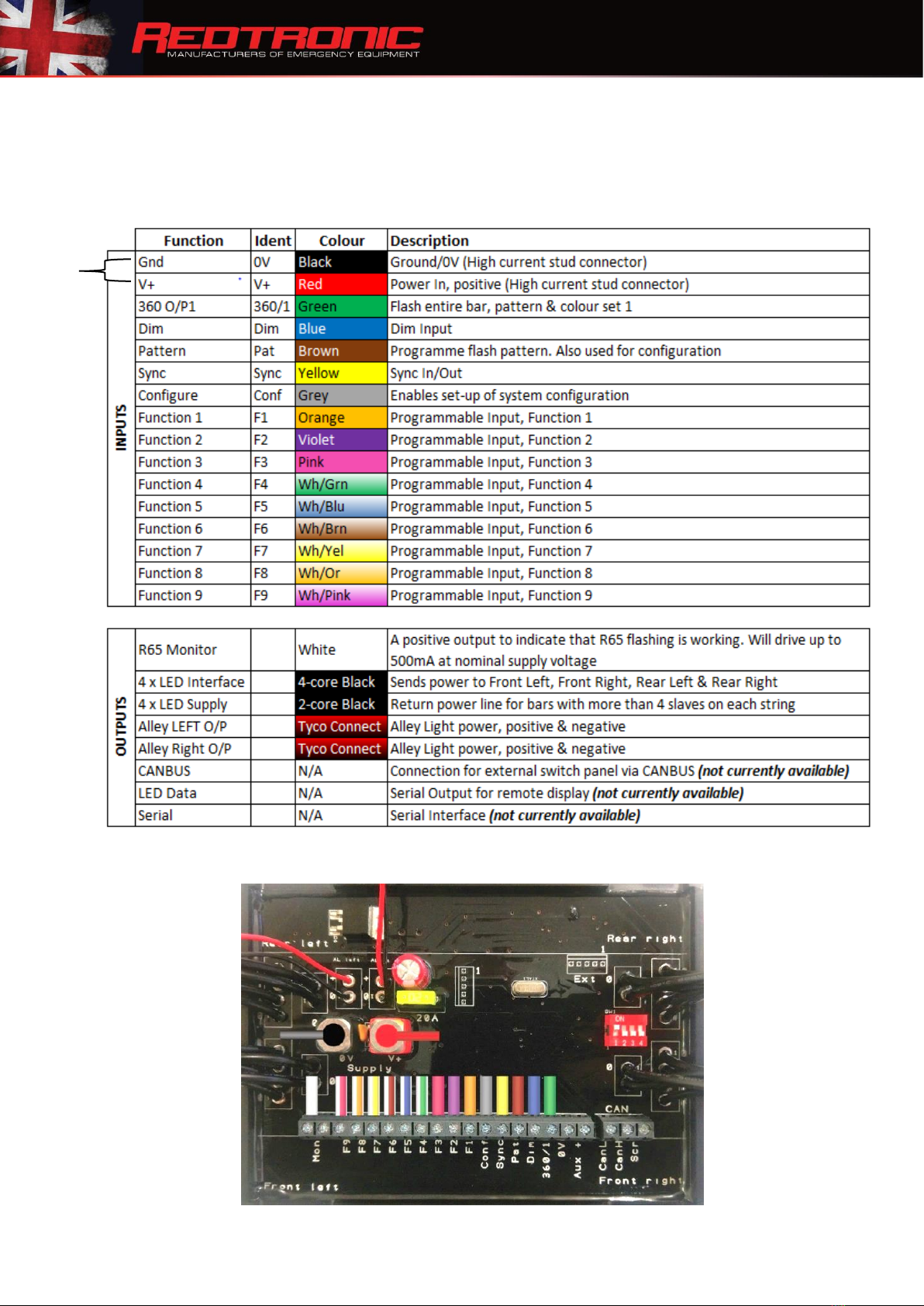
a) Ensure the Lightbar is in ‘Standby’ mode by connecting Red +ve Black -ve
b) Apply the Alley Left & Alley Right input wires to +ve permanently
c) Apply the brown (Pattern Select) wire to +ve momentarily
d) The Alley Lights will now flash in an alternating pattern
e) To Revert to ‘Permanent on’ apply the brown (Pattern Select) wire to +ve momentarily
f) If wanting to use more than ‘alley light’ for illumination, simply Apply the grey
(Config) wire to +ve permanently
a) Apply the brown (Pattern Select) wire to +ve momentarily
b) Release the grey wire
Note: Changing Alley Lights to ‘Flash’ will not affect the pattern of the lightbar when it is
not selected
6.0 CAP168 / ICAO / CAA / ACAA (whilst in 360/1, 360/2, Cruise Mode, Rotate patterns) - (61fpm)
This function is built-in to the Cruise and Rotate flash patterns as standard. If you require it
on another wire, setting Dil Switch 2 to ‘ON’ gives the addition of CAP168 pattern (Airport
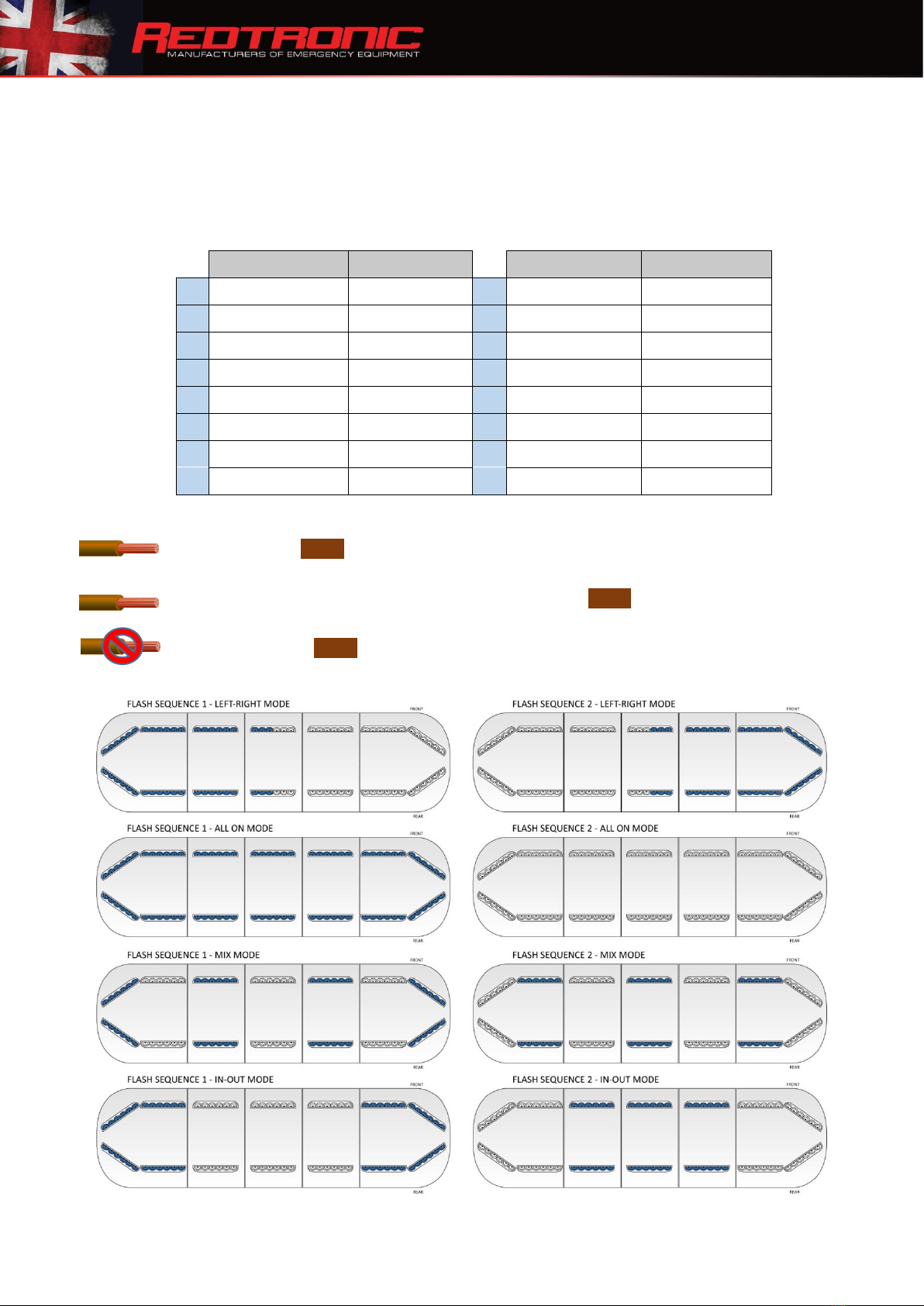
Mode) to the 360/1, 360/2 flash pattern options –in all 4 different flash modes (left-right,
all-on, mix, in-out). In addition, the colour can be individually set to each output (refer to 9.0
Setting the Colour)
6.1 360/1 & 360/2 Outputs
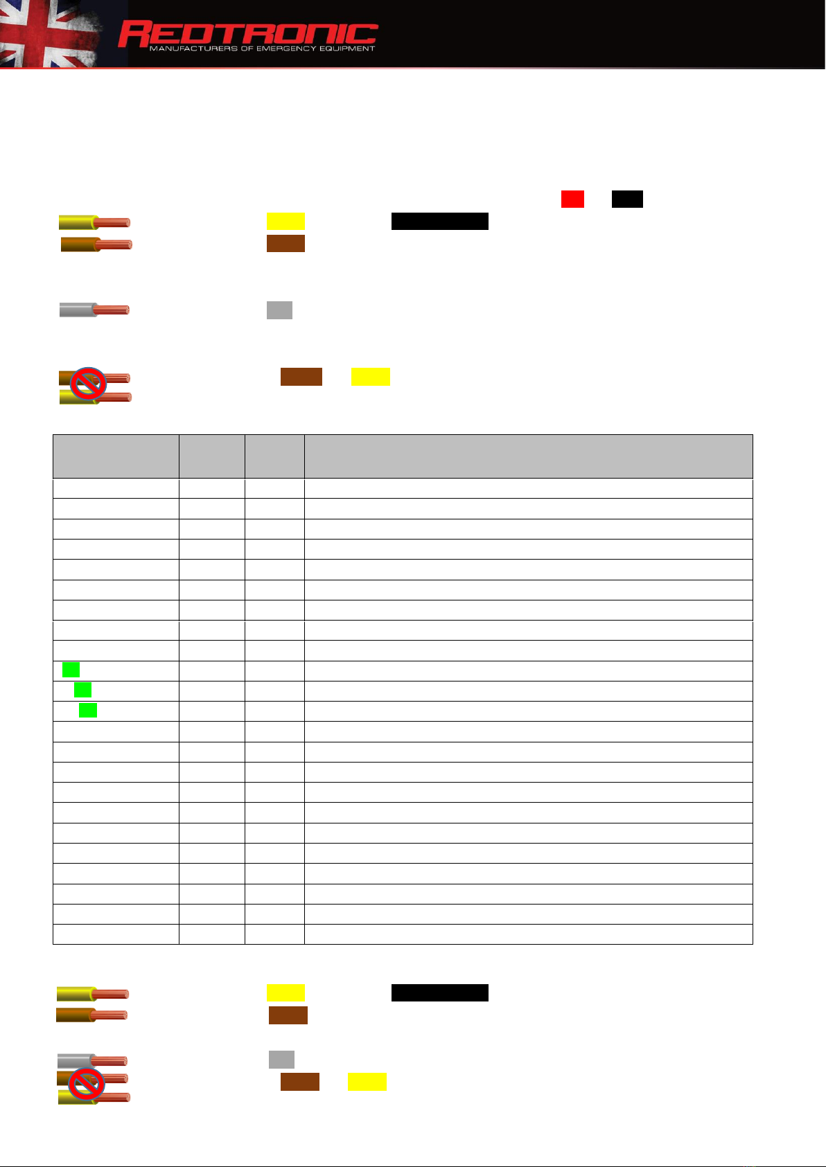
a) Ensure the Lightbar is in ‘Standby’ mode, set Dil Switch 2 to ‘ON’
b) Apply the input wire programmed as ‘360/2’ to +ve permanently
c) Apply the brown (Pattern Select) wire to +ve momentarily until CAP168 is enabled
6.2 Cruise Mode
a) Apply the input wire programmed as ‘Cruise Mode’ to +ve permanently
b) Apply the brown (Pattern Select) wire to +ve momentarily until CAP168 is enabled
6.3 Rotate
a) Apply the input wire programmed as ‘Rotate’ to +ve permanently
b) Apply the brown (Pattern Select) wire to +ve momentarily until CAP168 is enabled
7.0 Setting Dim Mode
There are two modes available with the Lightbar; 25% brightness and 50% of full brightness (default).
Dim does not apply to Stop/Tail/Indicator, Alley Lights, Worklamps or Front Floods.
a) Ensure the Lightbar is in ‘Standby’ mode
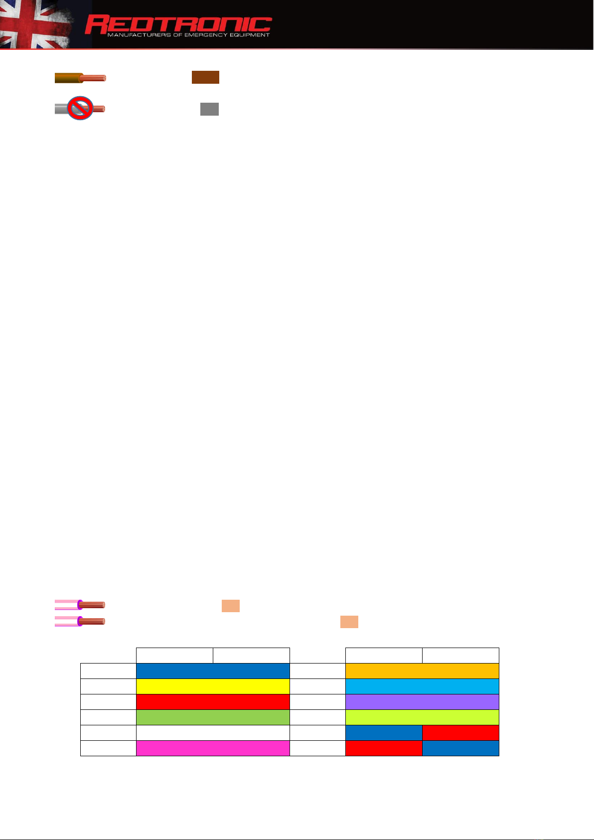
b) Apply the green (360/1) wire to +ve permanently
c) Apply the blue (Dim) wire to +ve permanently
d) Dim is now enabled at 50% of full brightness on all inputs
To decrease to 25% of full brightness: -
a) Apply the green (360/1) wire to +ve permanently
b) Apply the blue (Dim) wire to +ve permanently
c) Apply the grey (Config) wire to +ve permanently

M003 Issue: 1.5 Created by: Technical Dept. 6 February 2020
d) Apply the brown (Pattern Select) wire to +ve momentarily
e) Lamps will reduce in brightness
f) Release the grey wire
g) To revert back to default setting simply repeat the process
Note 25% Dim mode does not meet the requirements of the R65 candela (brightness)
specification
8.0 ECE R65 Monitor Output
The monitor output activates when the Lightbar is flashing with R65 compliance. Detected faults,
such as loss of communication to the board, will prevent the signal from activating. Any detected
fault will cause the LED to flash.
The minimum requirement for R65 compliance is activation of the end ‘angled’ modules in the
Lightbar, on full brightness. The monitoring output will therefore activate when these lamps are
performing correctly. If other lamps fail for any reason, the monitor output will still activate. This is
not a ‘full Lightbar monitor’.
The monitor output wire (white) can be connected to an external LED signal, buzzer or computer to
monitor ECE R65 compliance. This is a positive output that will drive upto 500mA at nominal voltage
supply. Please do not put a heavy load to this wire connection. When there is non-compliance to the
standard, the signal will deactivate.
9.0 Setting the Colour
This is not applicable to any lightbars built as ‘single colour’ only.
Setting Dil Switch 1 (located on the main internal motherboard) to ‘ON’ restricts the colour selection to 3 full
output colours only (i.e. whichever LED is mounted within lighthead). This will normally be set at the factory
on all Single and Dual colour models.
On Dual and Multi-Colour Lightbars, a colour can be set to each function as required by the user:
a) Ensure the Lightbar is in ‘Standby’ mode
b) Apply the required input wire (360/1 or F1-F9) to +ve permanently
c) Apply the white/pink (Colour select) wire to +ve momentarily until desired colour is set
d) To return to the first colour, apply the white/pink to +ve permanently for three (3)
seconds
Left Side
Right Side
Left Side
Right Side
Colour 1
Blue
Colour 7
Dark Amber
Colour 2
Amber
Colour 8
Light Blue (Green tint)
Colour 3
Red
Colour 9
Purple
Colour 4
Green
Colour 10
American Amber (Green tint)
Colour 5
White
Colour 11
Blue
Red
Colour 6
Magenta (Pink)
Colour 12
Red
Blue

M003 Issue: 1.5 Created by: Technical Dept. 7 February 2020
10.0 Programming the Lightbar
10.1 Setting an Input Function
Nine inputs (F1-F9) can each be programmed to perform 23 optional functions
a) Connect all the input wires to the LBAR Main Controller (refer to section 4.0)
b) Ensure that the Lightbar is in ‘Standby’ mode by connecting Red +ve Black -ve
c) Apply the yellow (sync) wire to -ve permanently
d) Apply the brown (Pattern Select) wire to +ve permanently for 5 seconds, diagnostic
LED will display 4 short flashes –do not proceed to next stage without this ‘pause’
e) Apply the required input wire individually (F1-F9) to +ve permanently
f) Apply the grey wire (Config) momentarily to +ve to cycle through to the required
function. Diagnostic LED will flash to confirm the function has been selected (refer to
Appendix 2)
g) Release the brown and yellow wire
h) The F1-F9 input is now programmed to the desired function
i) Simply repeat the process until all the F1-F9 inputs have been programmed
Input Function
Feature
Code
Default
Selectable Function
360 O/P 2
1
F4
Flash Entire Bar (Rear off as standard)
Colour
2
F9
Programme Colour
Left
3
F1
Main Traffic Director Left
Right
4
F2
Main Traffic Director Right
Centre
5
F3
Main Traffic Director Centre
Rotate
6
F6
Rotate Ends
Front Only
7
Flash Front Only
Rear Only
8
F5
Flash Rear Only
Cruise Mode
9
Glow Ends (Cruise Mode)
FF1 Front Flood Flash
10
Selected LED's Flash starting in front position (can also be made to steady burn)
FF2 Front Floods
11
Selected LED's Permanent On starting in front position (can also be made to flash)
FF3 Flexi-Flash
12
Selected LED's Flash starting in rear position (can also be made to steady burn)
Alley Left
13
F7
Alley Left
Alley Right
14
F8
Alley Right
Stop Light
15
Stop Light, Full Then 50% Brightness
Tail Light
16
Stop Light 25% Brightness
Indicator Left
17
Indicator Left
Indicator Right
18
Indicator Right
Left Front
19
Front Traffic Director Left
Right Front
20
Front Traffic Director Right
Centre Front
21
Front Traffic Director Centre
Rear Worklamp
22
Steady Work Light Rear
360° Worklamp
23
Steady Work Light All-Round
10.2 To reset an input to the first function in the list (360 O/P 2 - Flash entire bar)
a) Apply the yellow (sync) wire to -ve permanently
b) Apply the brown wire to +ve permanently
c) Apply the required input wire to +ve permanently
d) Apply the grey wire to +ve for two (2) seconds
e) Release the brown and yellow wire
f) Input is now set to the first function

M003 Issue: 1.5 Created by: Technical Dept. 8 February 2020
11.0 Traffic Director
By default, the three main Traffic Director (TDIR) inputs are setup to operate on the Rear Only.
However, the inputs can also be programmed to operate as Front Only, Front & Rear or Front & Rear
opposite. Additionally, the colour can be set individually to each input (refer to 9.0 Setting the Colour)
You can also setup the length of the TDIR and select optional ‘chase’ mode (whereby lightheads stay lit
when they have been activated).
11.1 Traffic Director Rear Only (Default input wires)
Orange (F1) = TDIR Left Pink (F3) = TDIR Centre Out Purple (F2) = TDIR Right
11.2 Changing Traffic Director Operation (Rear, Front, Front & Rear,Front & Rear Opposite)
a) Ensure the Lightbar is in ‘Standby’ mode
b) Apply the yellow (sync) wire to -ve permanently
c) Apply the orange (TDIR Left) wire to +ve permanently
d) Apply the grey (Config) wire to +ve permanently
e) Apply the brown (Pattern Select) wire to +ve momentarily until the required operation is set
f) Release the grey and yellow wires
11.3 Warning Lamp Mode
a) Ensure the Lightbar is in ‘Standby’ mode
b) Apply the orange & purple wires to +ve permanently
If more than one TDIR function is selected the Lightbar will resort to a programmable
‘Warning’ flash as a safety measure. Pattern setting is shared with the Flexi-Flash function
(see 12.12 Flexi-Flash), therefore changing one will affect the other. Colour can be set to
either function as required (See 9.0 Setting the Colour)
11.4 Setting Traffic Director Length
a) Ensure the Lightbar is in ‘Standby’ mode
b) Apply the yellow (sync) wire to -ve permanently
c) Apply the purple (TDIR Right) wire to +ve permanently
d) Apply the grey (Config) wire to +ve permanently
e) Apply the brown (Pattern Select) wire to +ve momentarily until the required length is set
f) Release the grey and yellow wires
11.5 Enable ‘Chase’ Mode
a) Ensure the Lightbar is in ‘Standby’ mode
b) Apply the yellow (sync) wire to -ve permanently
c) Apply the pink (TDIR Centre Out) wire to +ve permanently
d) Apply the grey (Config) wire to +ve permanently
e) Apply the brown (Pattern Select) wire to +ve momentarily
f) Release the grey and yellow wires
g) ‘Chase’ mode is now enabled on ALL Traffic Director operations
h) Repeat the process to revert back

M003 Issue: 1.5 Created by: Technical Dept. 9 February 2020
12.0 Additional Programmable Inputs
These are functions that may be set to any of the inputs (F1-F9). The user can assign the function if it
has not been set in the factory, however this will mean replacing an already programmed input if
there are no spare function wires available. Pattern and Colour (Dual and Multi-Colour only) are
selectable
12.1 Front/Rear Split - Setting mode –allows separate control of the front OR rear of the
lightbar individually on 2 separate feature wires
a) Follow section 10.1, selecting feature code 7 for Front mode
b) Follow section 10.1, selecting feature code 8 for Rear mode
12.2 ‘Cruise’ Mode - Both ends of Lightbar glow on ‘steady burn low power’
a) Follow section 10.1, selecting feature code 9
Note: CAP168 (Airport Mode) is incorporated into Cruise & Roto flash patterns. Applying
the brown (Pattern Select) wire to +ve will enable CAP168 (see 6.0)
12.3 Front Flood Flash (Takedown lamps) –Selected Front Modules flash (normally white lamps)
a) Follow section 10.1, selecting feature code 10
b) To ‘alternate’ the flash mode against 360/1, 360/2, flexi-flash or other mode (if not
restricted) –simple apply the brown (Pattern Select) wire to +ve for five (5)
seconds –this will alternate the flash pattern against the main function. To revert
–repeat operation.
12.4 Front Floods - Set selected modules to permanent on
a) Follow section 10.1, selecting feature code 11
12.5 Stop lamp - Factory fitted but can be installed as an upgrade (see 13.0 Lightbar Upgrades) –only
available to set up on the ‘rear’ of the lightbar (feature unavailable at front)
You must utilise 2 x BL.ADSTI for this function to work –setting this feature on a standard lightbar
lamp will void warranty
a) Follow section 10.1, selecting feature code 15 for Stop lamp
b) The lamps at the rear should light up REAR CENTRE module
c) Apply the yellow (sync) wire to -ve permanently
d) Apply the grey (Config) wire to +ve permanently
e) Apply the brown wire to +ve momentarily until the required module sections are lit –
you can cycle through various lamp positions at this stage –with a maximum length of 1
full module –the modules split into half to allow for STI setup using BL.ADSTI, each time
it will return to the centre to allow you to select the correct position
f) Once setup in the correct position: Release the grey and yellow wires

M003 Issue: 1.5 Created by: Technical Dept. 10 February 2020
12.6 Tail - Factory fitted but can be installed as an upgrade (see 13.0 Lightbar Upgrades)
You must utilise 2 x BL.ADSTI for this function to work –setting this feature on a standard lightbar
lamp will void warranty
g) Follow section 10.1, selecting feature code 15 for Stop
h) Follow section 10.1, selecting feature code 16 for Tail for the wire connection to
run this feature
i) Once set, the tail lamps should appear in the same position you have set up for
STOP.
12.7 Left Indicator –sets the REAR INDICATOR positions
You must utilise 2 x BL.ADSTI or 2 x BL.ADIND for this function to work as expected –setting this
feature on a standard lightbar lamp does not meet UNECER6 & UNECER7 homologation
requirements unless the specified lamps are utilised.
This setup procedure sets up the REAR POSITION of the Indicators in the lightbar. If you want to set
up FRONT POSITION indicators only, please see 12.8
a) Follow section 10.1, selecting feature code 17 for Indicator Left
b) The lamps at the rear should light up REAR CENTRE INDICATOR positions (Front
indicators will light up if active)
c) Apply the yellow (sync) wire to -ve permanently
d) Apply the grey (Config) wire to +ve permanently
e) Apply the brown wire to +ve momentarily until the required module sections are lit –
you can cycle through various lamp positions at this stage –with a maximum length of
1 full module –the modules split into half to allow for STI setup using BL.ADSTI, each
time it will return to the centre to allow you to select the correct position - the ‘off’
position is a part of this setup procedure, so if you do not want ‘REAR INDICATORS’
leave the lamps in the ‘off’ position in order to ensure no lamps light up upon
activating an indicator line
f) This is setting the REAR position –so depending on how the lightbar is already set up,
some front lamps may be lit –in order to turn these off, you need to set up Right
Indicator –see 12.8
g) Once setup in the correct position: Release the grey and yellow wires
12.8 Right Indicator - sets the FRONT INDICATOR positions
You must utilise 2 x BL.ADSTI or 2 x BL.ADIND for this function to work as expected –setting this
feature on a standard lightbar lamp does not meet UNECER6 & UNECER7 homologation
requirements unless the specified lamps are utilised
a) Follow section 10.1, selecting feature code 18 for Indicator Right
b) If you already set up the LEFT INDICATOR then the position will already be set –if not,
please follow section 12.7
c) You may find that the FRONT INDICATOR positions are lit –these can now be turned
off using the following procedure:
d) Apply the yellow (sync) wire to -ve permanently
e) Apply the grey (Config) wire to +ve permanently
f) Apply the brown wire to +ve momentarily until the required module sections are lit on
the FRONT of the lightbar –you can cycle through various lamp positions at this stage –

M003 Issue: 1.5 Created by: Technical Dept. 11 February 2020
with a maximum length of 1 full module –the modules split into half to allow for STI
setup using BL.ADSTI, each time it will return to the centre to allow you to select the
correct position –the ‘off’ position is a part of this setup procedure, so if you do not
want ‘FRONT INDICATORS’ leave the lamps in the ‘off’ position in order to ensure no
lamps light up upon activating an indicator line
g) This is setting the FRONT position –so depending on how the lightbar is already set up,
some front lamps may be lit –in order to turn these off, you need to set up Left
Indicator –see 12.7
h) Once setup in the correct position: Release the grey and yellow wires
12.9 Rear Worklamp - Set selected modules to permanent on
a) Follow section 10.1, selecting feature code 22 for Rear Worklamp
b) Apply the yellow (sync) wire to -ve permanently
c) Apply the grey (Config) wire to +ve permanently
d) Apply the brown wire to +ve momentarily until the required modules are lit –you can
cycle through various lamp positions at this stage, with each cycle it will ‘add’ a lamp
position into the chain, you can end up lighting the whole rear bar with this feature.
e) Release the grey and yellow wires
12.10 Rear Worklamp - Set front / rear operation
a) Follow section 10.1, selecting feature code 22 for Rear Worklamp
b) Apply the yellow (sync) wire to -ve permanently
c) Apply the grey (Config) wire to +ve permanently
d) Apply blue (Dim) wire to +ve permanently
e) Apply the brown (Pattern Select) wire to +ve momentarily This will cycle the lamps
through Rear only –Front only - Front/Rear –Rear only
f) Release the grey and yellow wires
12.11 360 Worklamp - Steady work light all round
a) Follow section 10.1, selecting feature code 23 for 360° Worklamp

M003 Issue: 1.5 Created by: Technical Dept. 12 February 2020
12.12 Flexi-Flash (FF) - Flash selected modules, in a variety of positions
Flexi-Flash allows the user to set a single LED module (or multiple modules) programmed to
this input function, in any desired format, giving the user total flexibility. This function can be
used to set up individual lightheads to flash or steady burn as required on the rear or front of
the lightbar, on either side or both sides. It also has independent flash pattern and colour
select on each setting.
In this version of software (v2.1) we have made it so there are 2 x more flexi-flash
functions, so on 3 separate wires, you can set up 3 different features rather than the
original 1 wire option. This is helpful to be able to set up a variety of new features in the
lightbar.
a) Follow Section 10.1, selecting feature code 10-12 (FF1, FF2, FF3)
12.13 Changing Flexi-Flash Operation –this selects the ‘position’ of the lamp within the Lightbar such as
rear, front, front & rear and/or side (See Fig 1).
a) Ensure the Lightbar is in ‘Standby’ mode
b) Apply the programmed Flexi-Flash input wire to +ve permanently
c) Apply the yellow (sync) wire to -ve permanently
d) Apply the grey (Config) wire to +ve permanently
e) Apply the blue (Dim) wire to +ve permanently
f) Apply the brown (Pattern Select) wire to +ve momentarily until the required operation is
set
g) Release the grey , blue and yellow wires
Flexi-Flash Sequence
1
Rear Only
6
Front Right only
2
Front Only
7
Front Left only
3
Front & Rear
8
Front & Rear Right only
4
Rear Right only
9
Front & Rear Left only
5
Rear Left only
Sync -ve
Permanent On
h) To ‘alternate’ the flash mode against 360/1, 360/2, another flexi-flash or other
mode (if not restricted) –simple apply the brown (Pattern Select) wire to +ve for
five (5) seconds –this will alternate the flash pattern against the main function. To
revert –repeat operation.
12.14 Setting Flexi-Flash LED Modules - this selects how many lamps (and which ones) activate for the
function, as shown in Fig 2).
a) Ensure the Lightbar is in ‘Standby’ mode
b) Apply the programmed Flexi-Flash function wire to +ve permanently
c) Apply the yellow (sync) wire to -ve permanently
d) Apply the grey (Config) wire to +ve permanently
e) Apply the brown (Pattern Select) wire to +ve momentarily until the required number
of LED modules is set
f) Release the grey and yellow wires

M003 Issue: 1.5 Created by: Technical Dept. 13 February 2020
Fig. 1
Fig. 2

M003 Issue: 1.5 Created by: Technical Dept. 14 February 2020
12.15 Inclusion / Exclusion flag
Within the lightbar, there are various features, mainly on ‘single colour modules’ that may ‘clash’
with another feature setup on the lightbar.
For example: Below the lightbar is set up as Blue 360/2 (Blue lights) –but you wouldn’t want the
traffic director to flash in Amber when the Blues are flashing as standard –in such case –you use
this ‘inclusion / exclusion flag’ feature on setup to eliminate the Amber lights from flashing whilst
the Blue lights are active on 360/1
a) With the Lightbar in ‘Standby’ mode
b) Apply the relevant function wire to +ve permanently (for instance as 360/2)
c) Apply the grey wire to +ve permanently
d) Apply the brown wire to +ve momentarily
e) This will either turn off the lamps that you do not want to appear in the setup or will
turn them on (if required)
f) Release the grey wire
g) Repeat the process to revert back
This feature does have many formulated setups available, but in general we would request that
if you are experiencing problems with setting up the ‘inclusion / exclusion flag’ you need to
contact the factory to ensure the function you are trying to include or exclude is possible.

M003 Issue: 1.5 Created by: Technical Dept. 15 February 2020
13.0 Lightbar Upgrades
The unique design of the Bullitt Advanced permits certain user upgrades to be carried out giving
improved visibility or additional functionality, such as Traffic Director, Stop/Tail/Indicator or Alley
Lights. Some programming will be required dependant on the type of upgrade (refer to 10.0
Programming the Lightbar). Please contact your sales representative to confirm that the upgrades
you require are possible before proceeding
When carrying out any upgrade, the Lightbar should ideally be de-installed from the vehicle. Where
this is not practicable, the Lightbar MUST be isolated from the vehicle’s battery. Failure to do so
may result in the Lightbar being reset to factory settings.
13.1 LED Modules
a) Carefully remove the M4 and M6 socket cap screws and washers from the top lenses
and place to one side
b) Remove the top lenses and place carefully to one side. Ensure that the silicone rubber
seals remain in place within the base lenses
c) Position the LED module(s) into the base lens, ensuring it is seated correctly on the base
lens stanchions

M003 Issue: 1.5 Created by: Technical Dept. 16 February 2020
d) Connect the module to the existing string via the 4-way connector
e) If the string contains four (4) or more LED modules the return connector loom on the
LBAR Main Controller must be used:

M003 Issue: 1.5 Created by: Technical Dept. 17 February 2020
f) With the new LED modules in position, carefully replace the top lenses and secure using
the M4 and M6 socket cap screws and washers - All fixings must be inserted with a
torque setting of 1.8Nm (18.4Kg/cm, 15.9in/lbs, 1.33ft/lbs)
g) Reconnect to the vehicle battery
h) Refer to 10.0 Programming the Lightbar
i) For Dual and Multi-Colour Lightbars refer to 9.0 Setting the Colour
13.2 Adding Alley Light modules (EM315WC/BL (internal stock code S.EM315WC/BL)
a) Carefully remove the M4 and M6 socket cap screws and washers from the top lenses
and place to one side
b) Remove the top lenses and place carefully to one side. Ensure that the silicone rubber
seals remain in place within the base lenses
c) Position the Alley Light(s) into the base lens end section, ensuring it is seated correctly (Fig. 1)
d) Connect the 2-core cable for each Alley Light to the LBAR Main Controller (Fig. 2)
e) With the Alley Lights in position, carefully replace the top lenses and secure using the
M4 and M6 socket cap screws and washers - All fixings must be inserted with a torque
setting of 1.8Nm (18.4Kg/cm, 15.9in/lbs, 1.33ft/lbs)
Fig. 1

M003 Issue: 1.5 Created by: Technical Dept. 18 February 2020
f) Reconnect to the vehicle battery
g) Alley Lights are normally connected to F7 (white/yellow) and F8 (white/orange), therefore
there is no requirement to programme the input as this is the default wiring
h) Should any other input wire be used refer to 10.0 Programming the Lightbar
i) Refer to 5.2 to set the required operation of each Alley Light
14.0 Fuse Requirements
The following table can be used as a guide to determine the maximum current for standard builds.
24v vehicles will draw approximately half the current shown in the table below. Installers should
contact their sales representative if unsure of the fusing requirements
Lightbar
Size
Type
No. of
LED's
Flash
Pattern
3 Watt
Max Current 12v
Dim Mode 50%
Max Current
12v
Dim Mode 25%
Max Current
12v
55cm
BL3
48
Double
1.2 Amps
0.6 Amps
0.3 Amps
71cm
BL2
96
Double
2.4 Amps
1.2 Amps
0.6 Amps
88cm
BL2
144
Double
3.5 Amps
1.7 Amps
0.85 Amps
105cm
BL3
168
Double
4 Amps
2 Amps
1 Amp
121cm
BL3
192
Double
4.6 Amps
2.3 Amps
1.15 Amps
138cm
BL3
216
Double
5.2 Amps
2.6 Amps
1.3 Amps
154cm
BL3
240
Double
5.8 Amps
2.9 Amps
1.45 Amps
171cm
BL3
264
Double
6.48 Amps
3.24 Amps
1.6 Amps
187cm
BL3
288
Double
7 Amps
3.5 Amps
1.75 Amps
204cm
BL3
312
Double
7.6 Amps
3.8 Amps
1.9 Amps
Fig. 2

M003 Issue: 1.5 Created by: Technical Dept. 19 February 2020
15.0 Synchronisation (Sync)
The Sync input/output is used to synchronise flashing with other Redtronic products. The Sync wire
(yellow) should be connected to all other products that require synchronising with the Lightbar.
DO NOT APPLY THE YELLOW WIRE TO +VE SUPPLY IN ANY CIRCUMSTANCE.
16.0 Restore Factory Settings
In extreme cases, it may be necessary to restore the Lightbar to factory settings
a) Ensure the Lightbar is in ‘Standby’ mode
b) Apply the brown (Pattern Select) wire to +ve permanently
c) Apply the blue (Pattern Select) wire to +ve permanently
d) Apply the green (360/1) wire to +ve permanently
e) Apply the yellow (sync) wire to -ve permanently
f) Apply the grey (Config) wire to +ve momentarily
g) Release the brown and green wires
h) Factory settings have now been restored
i) To re-programme to user specification refer to 10.0 Programming the Lightbar
Default Factory Settings
Other manuals for BULLITT ADVANCED
1
Table of contents
Other Redtronic Lighting Equipment manuals
Popular Lighting Equipment manuals by other brands

North Light
North Light WX-31VLED44-200WW-10-1 manual

Astral Pool
Astral Pool 00251 Installation and maintenance manual

Lightmybricks
Lightmybricks LEGO STORMTROOPER HELMET LIGHT KIT installation guide

HQ Power
HQ Power VDLL300TF user manual

Compu Pool Products
Compu Pool Products CPSC instructions

Show Tec
Show Tec City Painter 150 Product guide

Sunco
Sunco EX 2H-RED user manual

Lightmybricks
Lightmybricks LEGO UCS RAZOR CREST installation guide

HAMPTON BAY
HAMPTON BAY HB-10521-HS Use and care guide

Dop Choice
Dop Choice OCTA 5 operating instructions

superbrightleds
superbrightleds FLD-CNL-60005-100W user manual

Show Tec
Show Tec Cameleon Spot 18 Q6 V1 user manual