Refine A7 User manual

RF-APL-M001-1.2
Model: A7

For your safety and the safety of your patients please read this user manual carefully
before use and le for future reference.
This manual is published by Manufacturer.
We do not guarantee its contents and reserves the right to amend at anytime without
prior notice, amendments will be published in new editions of this manual.

Contents
1. Intended Use .....................................................................................................................................1
2. Precautions ........................................................................................................................................1
3. Contraindication ...............................................................................................................................2
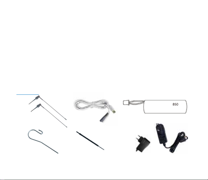
4. Package Contents .............................................................................................................................3
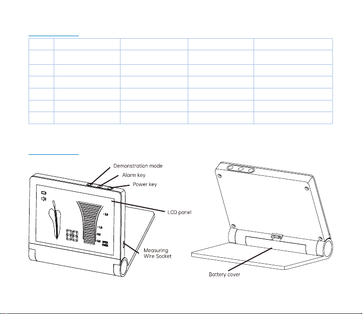
5. Component .......................................................................................................................................4
6. Installation .........................................................................................................................................7
7. Operation ...........................................................................................................................................8
8. Audio Alarm Volume Control...........................................................................................................11
9. Maintenance ......................................................................................................................................11
10. Charging Battery .............................................................................................................................13
11. Regular Maintenance Checks ........................................................................................................14
12. Trouble Shooting ............................................................................................................................15
13. Specications ..................................................................................................................................20
14. Classication of Equipment ..........................................................................................................21
15. Operation Principle ........................................................................................................................21
16. Declaration of Conformity .............................................................................................................22
17. Transportation and Storage Environment ..................................................................................22
18. Symbols ............................................................................................................................................22
19. Warranty ...........................................................................................................................................23
20. Disposing Product ..........................................................................................................................23
21. EMC Information .............................................................................................................................24
(Electromagnetic Compatibility Information) ..................................................................................24

1
1. Intended Use
Intended use:
determination of the apical foramen position and measurement of the root canal length.
The product is only to be used in dental surgeries by qualied dental personnel.
2. Precautions
• All precautions should be read and understood before use.
• Equipment is only to be used for its specied intended use.
• Safety instructions are provided in order to prevent the risk of personal injury or damage to the device
and are classied as below in accordance with the level of potential risk.
WARNING: Indicates a hazard that may result in serious injury/device damage if
instructions are not correctly followed.
CAUTION: Indicates a hazard that may result in mild to moderate injury/device damage if
instructions are not correctly followed.
WARNING:
• Use this product in accordance with its intended use and proper method of use.
• This product is not waterproof. Avoid water or chemical solutions on the control unit as it may cause
electric shock due to a short circuit.
• The scale indication on the screen does not represent a distinct length or distance in mm or other linear
units. It simply indicates the le’s progression towards the apex.
• Do not expose to or dispose of the battery in a re.
• Be sure to prevent the lip hook , le clip , le probe and their connector parts from having contact with
household power supply sources (such as electrical outlets) as it may cause an electric shock.
• The components in the product package are delivered in a non-sterile condition, be sure to sterilize the
le clip, le probe and lip hook by autoclave sterilization prior to use and after each patient.
• Do not operate close to patients with cardiac pacemakers as there is a danger that it may affect the
pacemaker.
• Keep away from explosive substances and ammable materials.

1
CAUTION:
• Do not keep using the product when the battery indicator “ ” is ashing. Normal operation or
indication may not be performed. Please recharge the battery.
• Should the product function abnormally during operation, cease operation immediately.
• Do not use the product by connecting or integrating into other medical devices.
• Do not drop or allow impact on the product. This may result in personal injury or damage to the unit.
• Avoid using chemical solutions on the lip hook, le probe or le clip during procedures. Use of solutions
may cause inammation.
• When gripping the metallic part of a file or reamer with the file clip, grip the upper part (near the
handle). If the lower part (blade transition part and blade part) is gripped, the root canal length cannot
be correctly measured and the tip of the le clip may be broken.
• Do not use or leave the product in a high-temperature environment such as under strong direct
sunlight, or next to equipment that produces heat as it may cause overheating or re due to a failure of
the internal circuit.
• Do not attempt to disassemble the product nor tamper with the mechanism except as recommend by
manufacturer in this User manual.
• This device is for indoor use only.
• Keep the control unit on a level surface.
• If the product is not used for a long period check it is functioning correctly before using on a patient.
• Portable and mobile RF communications equipment can affect Medical Electrical equipment. Do not use
RF equipment near the product.
• During operation the Apex Locator may interfere with computers, LAN cables or may cause noise in
radio receivers nearby.
• Installation and use of this product requires special precautions regarding EMC according to the EMC
information.
• Use only original accessories with this device.
• The apical position is indicated on the screen with “00”. In order to avoid over instrumentation, it is
suggested to subtract 0.5mm from the reading when determining the working length for shaping.

2
• Always dry the cavity entrance with a cotton pellet in order to obtain an accurate measurement.
• Users are responsible for the operational control, maintenance and continual inspection of this product.
• The battery can be replaced, please contact our distributor if a replacement battery is required.
3. Contraindication
The Apex Locator is not recommended for use:
a. In patients who have a pacemaker or other implanted electrical devices or have been cautioned by
their physicians against the use of small electric appliances such as shavers, hair dryers etc.
b. In Patients allergic to metals.
c. Children.
4. Package Contents
Apex Locator is composed of a control unit, AC adapter, Plug adaptor, measuring wire, lip hook, le clip,
le probe .
Accessories
h
a). File Clip
d). Lip Hook e). File Probe f). AC adapter
b). Measuring wire c). Battery
ICR14500 3.6V 800mA

3
Accessories list
No. Name Quantity Consumable? Can be sterilized?
a File clip 4 PCS YES YES
b Measuring wire 1 PCS YES NO
c Battery 1 PCS NO NO
d Lip hook 4 PCS YES YES
e File probe 4 PCS YES YES
f AC adapter 1 PCS NO NO
5. Component
5.1 Control Unit

4
LCD Panel Displays the position of the le tip, remaining battery
level and alarm sound volume
Power key
When the Power key is pressed, the power turns on
sounding an alarm, then the LCD panel lights up, press the
Power key again, the power and the LCD panel turns off.
Alarm key When the Alarm key is pressed, the alarm audio volume
can be adjusted (rotation of OFF->Low->Medium->High).
Measuring wire socket Socket to which the measuring wire is inserted.
Battery cover Secures battery in place.
Charging light The light will remain on when battery is charging
Demonstration mode Press the button to demonstrate the measurement process
Charging socket Socket to which the AC adapter is inserted
5.2 LCD Panel
2
3
1
5
6
74

5
Bar graph Displays the approximate position of the end of the le
Batter
indicator
Displays the remaining battery level. When the Battery indicator flashes,
immediately recharge the device with AC adapter
Alarm indicator Displays the alarm audio volume
(rotation of OFF ->Low ->Medium ->High )
Number display
Displays the present position from the end of the root canal in numerical
value. When the value displays “10” to “05”, an alarm corresponding to each
value sounds. When the value reaches “04” to “00”, a short alarm sounds
with “APEX”displayed on the LCD panel. When the values reaches “-1” to “-3”, a
shorter alarm sounds with “OVER”displayed on the LCD panel
Apex indicator Turns on when the value representing the present position of the file end
reaches “00”
OVER Display Turns on when the value representing the present position of the file end
reaches “-1”
Measurement
indicator Indicates the les position in the root canal
* 4 is not a value to show the actual distance from the end of the root canal in the unit of mm. It is to be
used as indication for measurement.
6. Installation
1) Connect the measuring wire: securely insert the plug of the measuring wire into the Measuring wire
socket on the unit.(Fig.2)

6
2) Connect the le clip: connect the plug of the le clip to either plug of the measuring wire. (Fig.3)
3) Connect the lip hook: connect the lip hook to the other plug of the measuring wire. (Fig.3)
Fig.1 Fig.2 Fig.3
4) Make the lip hook touch the bent section of the le clip (Fig.4), the screen will display“OVER”,(as show
in Fig.5 c), otherwise, it means the le clip or the measuring wire is damaged, and should be replaced.
5) Display explanation
• “10 to 05”, Green bar graph and/or low frequency sound: File has reached the front region of the Apex;
• “04 to 00”, Yellow bar graph and/or middle frequency sound: File is very close to the Apex;
• “-1 to -3”, Red bar graph and/or high frequency sound: File has exceeded the Apex.
Display Screen explanation
a. The file has reached the front
region of the apex
b. The le is very close to the apex c) The file has already exceeded
the Apex
Fig.5

7
6) Demonstration mode
Demonstration mode tracks the movement of the le
a. Pull out the measuring wire and adapter.
b. Turn on Apex Locator
c. Press “ ”button for 2 seconds to enter demonstration mode
Demonstration mode will be exited by nishing demonstration or pressing demonstration mode button.
7. Operation
7.1 Preparation
7.1.1 The use of apex locators alone, without a preoperative and postoperative radio graph, is not a
recommended practice as apex locators may not work properlyin all conditions. It is recommended to
take an X-ray prior to the use of the Apex Locator, to compare the information given by both devices.
7.1.2 The dentist should have a good understanding of the tooth and root canal in question
7.1.3 The root cavity should be sufciently exposed and the root should be unblocked.
7.1.4 The largest le that can correctly reach the apex should be selected.
7.1.5 Avoid contact between the le, le clip and the gingiva or any metal crown and bridge appliances. If
the crown of the tooth is broken and there is a possibility of the gingiva contacting either the le, le clip
or a probe, an incorrect reading may occur. An isolating barrier around the rim of the broken tooth must
be created before proceeding with the Apex location.
7.1.6 Dry canals should be treated with an irrigation solution such as saline or hydrogen peroxide. Access
to the cavity should then be air dried or wiped dry with a cotton pellet.
7.1.7 If there is bleeding from the root canal or apical foramen, it must be stopped before a correct
measurement can be taken.
7.1.8 Canals must be cleaned of all remnants after root canal treatment before measurement can be
taken.
7.1.9 Accessories such as le clips, lip hooks and le probes should be clean and free from any chemical
disinfectant or medical solution residue.
7.1.10 Mark the treated tooth and record the information on the patients medical records. Be careful to

8
make sure the tooth is marked in a practical and most resilient part of the tooth.
7.1.11 The root canal must be cleared of any pulp or necrotic tissue and there must be no inammation or
infected material surrounding the apex.
7.1.12 The following cases are not for use with the apex locator.
a) The measurement length of the canal may be shorter than its real length due to root hypoplasia and
thus a true reading is not possible
b) A crack in the root may allow electric leakage thus affecting accuracy of the reading
7.1.13 An X-ray shot at a difcult or unusual angle may sometimes cause the illusion that the le tip has
not reached the apex. Results of the Apex Locator and X-ray may possibly not correlate falsely indicate
that the le tip has not reached the root canal tip. (Fig. 6)
7.2 Operating Procedure
7.2.1 Grip the le inserted in the root canal with the le clip. Grip the upper part (near
the handle) of the le’s metallic part. (Fig.7)
7.2.2 Hang the lip hook on a corner of the patient’s mouth. (Fig.8)
Fig.7
Fig.8
Endo le
File clip
Touch probe
7.2.3 Insert the le into the canal and push it slowly towards the Apex.A continuous alarm will sound
when the le is less than 2mm from the apex.Gloves must be worn to avoid contact of the operators skin
and metal shank of the le.
7.2.4 The “APEX” will be indicated when the screen displays “00” but as previously stated 0.5mm should
be subtracted from the reading so as to not over instrumentate.
7.2.5 When the file reaches this point, adjust the endo stop and remove the file. By measuring
the distance between the endo stop and the tip of the file, the working length of the canal can be
determined.

9
7.2.6 The le probe may also be used instead of the le clip to touch the le when working on posterior
to determine the working length of the canal. (Fig.9)
7.2.7 After use, press the Power key for approximately one second to turn off the power (the alarm
sounds and the LCD panel turns off). The device will shut down automatically after 5 minutes if unit is
not in operation.
7.2.8 Remove the le from the le clip.
7.2.9 Remove the lip hook and le clip from the measuring wire.
7.2.10 Remove the measuring wire from the control unit.
CAUTION:Never hold the measuring wire when removing the lip hook and file clip from the
measuring wire. Always hold the connector section.
8. Audio Alarm Volume Control
Alarm audio volume can be adjusted to “OFF ”, “Low ”, Medium ”, and “High ”.
1) press the Alarm key.
2) The Alarm Indicator on the LCD panel and the sound volume will change.
3) Each time the key is pressed the sound volume changes.
NOTICE
The last setting is stored when the control unit is switched off.
9. Maintenance
9.1 Cleaning
Preparation prior to cleaning
1. Remove the le clip and lip hook from the measuring wire.
2. Remove the measuring wire from the control unit.
3. Check for damage on each cord or deformation on each connector.
Cleaning
1. Rinse accessories thoroughly with clean suitable water, then wipe clean with alcohol-immersed cotton
or cloth.

10
2. Repeat until accessories are visibly clean.
Note:
a. Clean and sterilize the accessories before each use to prevent any contamination. This includes the
rst use as well as any subsequent use.
b. Accessories that should be cleaned include: measuring wire, le clip, lip hook, le probe.
c. Do not use highly acidic water to immerse or clean .
CAUTION:
Non observance of the following precautions could lead to the deterioration or
failure of the accessories. Be sure to follow these precautions when cleaning the accessories.
• When cleaning the product never use solvent such as benzine or thinner.
• Do not use a chlorinated cleaner.
• Do not clean the product with an ultrasonic cleaning apparatus.
• For your own safety, please wear personal protective equipment (gloves, glasses, mask)
• After cleaning the measuring wire, make sure to dry the connector part of the measurement wire.
9.2 Sterilization of the le clip, lip hook and le probe
Note: Sterilize le clip ,le probe and lip hook by autoclave sterilization, other parts Apex Locator can not
be sterilized.
Autoclave Procedure:
1) Insert into an autoclave pouch.
2) Seal the pouch.
3) Sterilize at 134oC (273oF) for 10 mins and a minimum drying cycle of 30 mins.
4) The product should remain in a sealed pouch until required for use.
CAUTION:
• The product must be cleaned before sterilization.
• Do not heat or cool the product too quickly. Rapid change in temperature could cause damage to the
product.
• Do not use Autoclaves exceeding 138oC during sterilization.
• We recommends sterilization according to EN13060, class B. Always follow autoclave manufacturer’s

11
instructions for use.
• Do not touch the product immediately after autoclaving as it will be very hot and must remain in a
sterile condition.
• Reprocessed products should be stored, protected from dust with minimum exposure to germs in a dry,
dark and cool place.
• Autoclave sterilization is the only agreed method to correctly sterilize this product. The validity of other
sterilization methods is not conrmed or guaranteed.
• Resistance to reprocessing: le clip: 200 cycles , other accessories have no cycle limitation, but should
be replaced when no longer in usable condition.
(reprocessing cycles include cleaning and sterilization).
10. Charging Battery
Do not use the Apex Locator whilst the indicator is ashing. Charge battery as below:
1) Connect the AC adapter to the Charging Socket of the device, then insert AC adapter plug into supply
power socket.
2) The Apex Locator will take approximately 2-3 hours to fully charge.
Attention:
a. Orange light indicates charging and will turn green once unit is fully charged.
b. Please do not use the device when it is charging.
c. We provide a plug adaptor for certain target markets, if the AC adapter can not match the supply
power socket, you can insert the plug of AC adapter into the Plug adaptor, then insert the Plug adaptor
into the supply power socket.
CAUTION:
• Avoid shorting the battery.
• Do not disassemble or tamper with the battery.
• Use the AC adapter provided by manufacturer (complies with IEC 60601-1) to charge the device, never
use a modied or damaged charger.
• Batteries will discharge over time if Apex Locator is not used. Always recharge if the unit has not been

12
used for extended periods.
• Only the NCM 14500 DC 3.6V/850mAh Rechargeable Li-ion Battery Cells which have passed the IEC
62133 certication can be used.
3) If you need to replace battery please contact us or your dealer.
How to install the battery:
a. Open the battery housing
b. Insert battery connector into the square notch
c. Make sure it is rmly installed by gently pulling the battery
d. Reinstall the battery housing
Note: the square notch is an anti-mistake design, if the polarity is reversed, the battery can not be
installed.
11. Regular Maintenance Checks
Regular maintenance should be performed every 3 months as per the below chart.
If any abnormalities are found, immediately contact our authorized dealer or us.
Points to check Process
ON/OFF operation Check that the power turns ON and OFF correctly
Remaining battery level Check that the Battery indicator does not flash. If the displayflashes,
recharge the battery following the instruction in “10.Charging battery”
Alarm sound volume Press the Alarm key and check that the alarm audio volume changes.
(rotation of OFF->Low->Medium->High)
Connector part Check for debris or corrosion on the lip hook or connector terminals of the
cable

13
Product operation
Check with the tester, that the cable and the control unit operate
properly, following the instruction in “6. Check before Treatment and
Installation”
* See trouble shooting chart if problems are discovered
12. Trouble Shooting
When a problem is detected, check the following again before requesting a repair.
Malfunction Cause Solution
The power does not
turn on
Battery is not inserted Insert battery
Battery is not correctly
inserted Correctly insert the battery
The battery level is low Recharge the battery
Root canal
length
measurement
cannot be
performed
The measuring wire or
other connectors are not
properly connected.
Securely insert the connector Connect the lip
hook and le clip and make the lip hook touches
the bent section of le clip to check whether the
device has been connected correctly.(refer to“6.
Check before Treatment and Installation”. )
Alarm sound volume
is low
The alarm sound volume is
adjusted to “OFF”. Check the alarm sound volume.
The LCD panel does
not display The battery level is low
If the LCD panel does not display after the
battery is charged, failure of the LCD panel is
suspected

14
Bar graph is
not stable
The lip hook is not rmly in
contact with the membrane
of the patient’s oral cavity
Adjust the lip hook position so that it correctly
contacts the membrane in the oral cavity
Perforation of the canal or
an adjacent surface has
caries
Remove the le , close the perforation and repair the
caries, then repeat the apex detection procedure,
carefully inserting the le in canal
Large lateral canal Try continuing the procedure by gently advancing
the le
The le is in contact with
the gingiva
When the le contacts the gingiva the entire bar
graph will light be lit up. Check if the le is in contact
with gingiva
The le is in contact with a
metal prosthesis.
When the le contacts a metal prosthesis, the
measured current ows to the gingiva or periodontal
tissues and the bar graph moves.Check if the le has
contacted a metal prosthesis
Current leakage to the
gingiva is occurring due to a
major collapse of the crown
Form a matrix around the tooth to prevent current
leakage to the gingiva

15
Bar graph is not
stable
The le clip is not clean
or is damaged Replace or clean the le clip
Bar graph does not
move
The root canal is closed
Bar graph operates correctly when the le reaches
the apical constriction. In this case, always check in
combination with X-ray photography
The inside of the root
canal is extremely dry. Moisten the root canal with a saline solution
Bad electrical contact Perform the cable connection test as described in“6.
Check before Treatment and Installation”
Bar graph does not
move
The connection hook of
le clip is not properly
connected to the le
Place the connection hook on the metal part of the
le below the plastic handle
In the case of
retreatment: residue
from old lling material
may be
blocking the root canal
Remove old root lling material residues prior to
measuring

16
Bar graph does not
move
Root canal may be blocked
by remnants of medical
products
(e.g. calcium hydroxide)
Rinse the root canal with NaCl solution. Dry the
access cavity with a cotton pellet/air-blower
The selected le is too small
for a large root canal
Use the largest file possible for the canal to
produce the most accurate result
Electronic malfunction Contact your distributor or us
Display indications
are incorrect, i.e.
unit displays that
“APEX” is reached
before it has
Short circuit due to excess
liquid(irrigation solution,
saliva or blood) in the pulp
chamber
Dry the access cavity with a cotton pellet/air
blower. In case of excess bleeding, wait until it
has stopped
A direct contact of the
le with the gingiva
proliferations or metal
restorations (crown,
amalgam lling)
For isolation:
A) Do adequate preparation lling.
B) Use a rubber dam or isolate the file by
placing 2-3 silicone stoppers on it
If none of these are applicable or if the trouble is not xed after the appropriate action has been taken, a
failure in this product is suspected. Contact our Authorized Dealer.
13. Specications
Model Apex Locator
Input (charge the battery) DC 5V 1A
Table of contents
Other Refine Dental Equipment manuals
Popular Dental Equipment manuals by other brands

DentalEZ
DentalEZ Star Titan Low-Speed manual

ShenPaz
ShenPaz Sintra PRO 90zr user manual

Durr Dental
Durr Dental Vector Scaler Installation and operating instructions

Dentsply Sirona
Dentsply Sirona DAC Universal Touch operating instructions

Renfert
Renfert Power-Pillo manual

Aseptico
Aseptico AEU-14CF Operations manual & parts list