Reflex Marine FROG-XT6-P User manual

USER MANUAL
Rev 1.1
Issue date: 19/02/2021
Original Instructions

UM-0203 Rev 1.1 1 | P a g e
Introduction
This manual contains information for operating, maintaining and storing the FROG-XT6-P
personnel carrier. Appropriate training and pre-operational briefings should be provided for
all personnel involved in the use of this device.
Risk awareness and planning - Crane transfers (like other forms of marine transfer) are
complex operations and operators must take account of a wide range of operational
variables. By their nature they usually require the management of an interface between two
separate organisations (most frequently an installation operator and a vessel operator). It is
essential that all the key risk factors are taken into account and proper planning and
preparation is done and that all personnel involved are aware of their roles and have the
necessary competence to perform them.
Best practice references - Please refer to Offshore Personnel Transfer by Crane. This is a
separate document that contains comprehensive guidance and information on each element
of operation. It is for those researching, planning, managing or carrying out the safest
possible crane transfers.
10 Golden Rules: Personnel Transfer by Crane video also provides a useful overview of the
key risks and considerations in planning crane transfer operations.
Key references
i. Offshore Personnel Transfer by Crane, Marine Transfer Forum,
http://www.marinetransferforum.org/resources
ii. 10 Golden Rules: Personnel Transfer by Crane, Reflex Marine,
https://www.youtube.com/watch?v=JDljjCqr2Zw
Safe and proper use of the FROG-XT6-P is the responsibility of the user, taking due
consideration to the information provided in this document. The user should ensure
compliance with all relevant legislation and good industry practice.
Control of manual –This manual is controlled by Reflex Marine and may be revised from
time to time. The latest revision may be obtained by contacting RML or by downloading the
latest version from www.reflexmarine.com/support.
Note
: For the purposes of this manual RML will be deemed to mean Reflex Marine Limited
All information disclosed in this document is the property of Reflex Marine Ltd except where otherwise stated.
Reflex Marine Ltd reserves all patent rights, design rights, manufacturing rights, copyright and sales use rights
thereto, and to any article disclosed within this document except where such rights are expressly granted to
others or where not applicable to vendor proprietary parts.
© 2020 Copyright Reflex Marine Ltd, all rights reserved.

UM-0203 Rev 1.1 2 | P a g e
Contents
Introduction ............................................................................................................................................1
1 Product Specifications.....................................................................................................................4
2 Operating Parameters.....................................................................................................................5
2.1 General....................................................................................................................................5
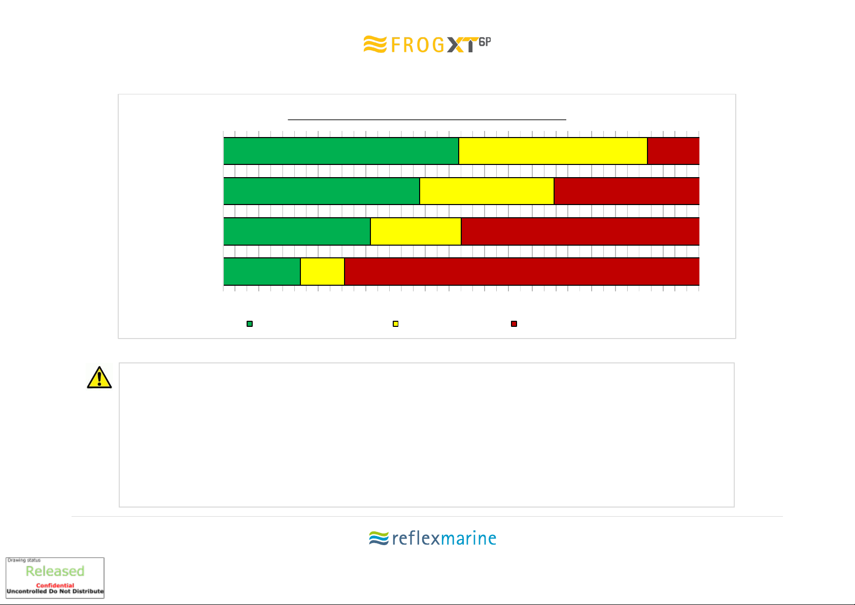
2.2 Recommended Operating Parameters ...................................................................................7
2.3 Crane Transfer Planning Tool..................................................................................................7
3 Using the FROG-XT6-P.....................................................................................................................8
3.1 Safety Features .......................................................................................................................8
3.2 Passenger Instructions............................................................................................................8
3.3 Entry and Exit..........................................................................................................................9
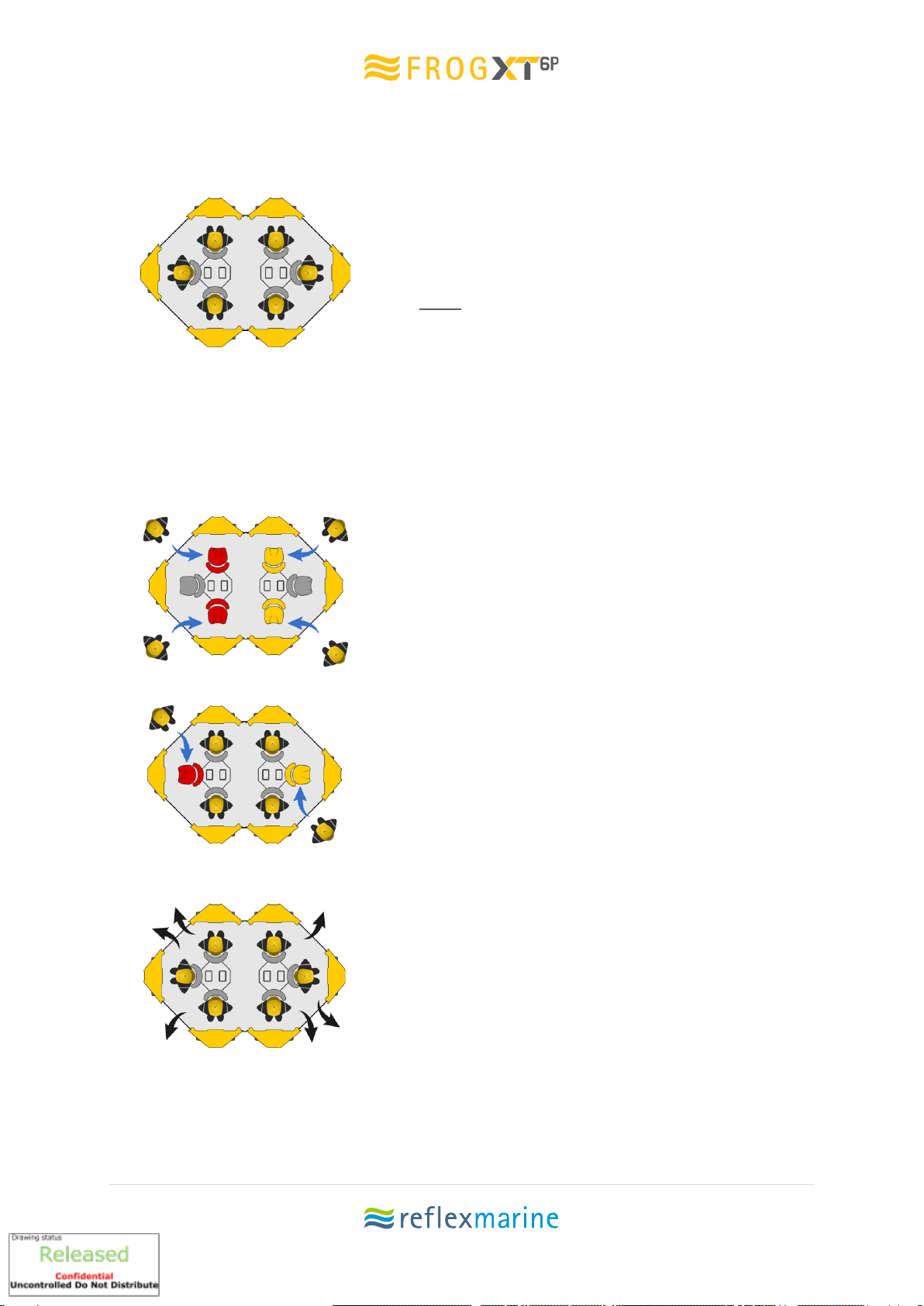
3.4 Passenger Flow .....................................................................................................................10
3.5 Deck Crew Instructions .........................................................................................................11
3.6 Passenger Instructions..........................................................................................................12
3.7 Safety Harness Procedure.....................................................................................................13
3.8 Stretcher Mode.....................................................................................................................14
3.9 Carrying Luggage...................................................................................................................18
3.10 Lifting Assembly Connection.................................................................................................19
3.11 Control of Lifting Assembly...................................................................................................20
4 Inspection & Maintenance............................................................................................................21
4.1 Definitions.............................................................................................................................21
4.2 Care in use / Preventative maintenance...............................................................................22
4.3 Inspection Types ...................................................................................................................24
4.4 Frequency..............................................................................................................................24
4.5 Supporting Documentation ..................................................................................................25
4.6 FROG-XT6-P Inspection and Maintenance Schedules...........................................................26
4.7 Load Test Procedure .............................................................................................................28
4.8 Load Testing Arrangements..................................................................................................29
4.9 Data plates ............................................................................................................................30
4.10 Pre-Use Check.......................................................................................................................31
4.11 Visual Inspection Checklist Form ..........................................................................................32
4.12 Examination Checklist Form..................................................................................................35
4.13 Post Load Test Inspection Checklist Form.............................................................................38
5 Handling & Storage.......................................................................................................................39

UM-0203 Rev 1.1 3 | P a g e
5.1 Stock Inspections ..................................................................................................................39
5.2 Forklift...................................................................................................................................40
5.3 Crane.....................................................................................................................................40
5.4 Securing.................................................................................................................................40
5.5 Inspection..............................................................................................................................40
5.6 Preparation for Road Transport............................................................................................40
5.7 Shipping.................................................................................................................................40
5.8 Storage..................................................................................................................................40
5.9 Feet Deformation during Storage.........................................................................................41
5.10 Replacement Parts................................................................................................................41
6 Replacement Parts........................................................................................................................42
6.1 Introduction ..........................................................................................................................42
6.2 Kits.........................................................................................................................................42
6.3 Parts identification................................................................................................................43
6.4 Accessories............................................................................................................................43
6.5 Luggage Options....................................................................................................................44
7 Certificates....................................................................................................................................45
7.1 EC Attestation of Conformity................................................................................................45
8 Contact Details..............................................................................................................................46

UM-0203 Rev 1.1 4 | P a g e
1Product Specifications
Table 1 Product Specifications
Model No.
XT6-P
Dimensions
(Nominal)
Width 1
3621 mm
Width 2 (Across Buoyancy)
2660 mm
Height
2180 mm
Weight
Maximum Gross Mass
1600 kg
Tare Weight
850 kg
Payload - SWL
750 kg
Materials
Frame
316L stainless steel, A4 stainless fixings
Central Column / Load Plate
316Ti stainless/ duplex stainless
Other Steel Components
All stainless except for floor grating
Buoyancy
Polyethylene (PE) moulded shell with
Polyurethane (PU) closed cell foam fill
Seat Base/ Seat Back
Polyolefin shell filled with polystyrene
closed cell balls
Landing Feet
EVA closed cell foam
Operating
Temperatures
Standard Model
-20°C to +50°C
Arctic Model
-40°C to +50°C
Suspension
Springs
4 x coated heavy duty coil spring
Dampers
4 x stainless steel 400mm recoil dampers
Seating
Seats
6 x full height seats
Harnesses
3-point, quick release buckle
Grab Handles
2 per buoyancy panel
Lifting Points
SWL
Main
1060 kg
Backup
1060 kg
Handling
1060 kg
Wire Rope
Lifting
Assembly
Safe Working Load
Two-leg lifting assembly: 1600 kg
Wire Rope
Galvanised steel wire rope
Number of
Passengers
Standard
6
Stretcher Mode 1 Stretcher
2 + 1 stretcher
Stretcher Mode 2 Stretchers
2 + 2 stretcher
Luggage
Capacity
Light Luggage
Accessory available on request
Large Luggage Tray
Accessory available on request
Impact
Protection
Vertical impacts
Passengers are protected during heavy
landings at speeds of up to 4.5 m/s
Lateral impacts
Passengers are protected from lateral
impacts at speeds of up to 2 m/s
Stability
Horizontal
35˚ for a load of 1-6 passengers
Submerged Self-Righting
Up to 180˚ inverted to the vertical position
Certification
Class
CE Marked by independent body
Quality
System
Manufactured to ISO 9001:2015
Standards
National Technical Standards
UK, BS EN 1993 series: ‘The Use of
Structural Steel in Building’
Industry European Standards
EC Machinery Directive
EN 14121-1, BS EN 12100-10
Load Test –ILO152 / LOLER
National Regulations
UK, PUWER / LOLER

UM-0203 Rev 1.1 5 | P a g e
2Operating Parameters
2.1 General
The FROG-XT6-P has been designed to ensure passenger safety in the most demanding
conditions.
There are a large number of factors that affect the safe conduct of marine personnel
transfers. These include: crew skill and experience, met-ocean conditions, landing areas,
vessel station keeping capability and response to sea conditions, visibility and line of sight. A
combination of many factors will determine the risk involved.
Sea State
The FROG-XT6-P has a suspension and damping system which prevents passengers from
experiencing shock loads up to relative velocities of 4.5 m/s. The maximum recommended
significant wave height is based on the maximum relative velocity between the load (or
hook) and the deck.
The calculated operational sea states detailed below are based on vertical impact speeds
and bio-mechanical considerations. They reflect the ability to withstand such impacts with
minimal risk of injury to the human body. However, there are many additional factors that
may affect the safety of crane transfer operations. These include vessel station-keeping,
crew competence, wind and visibility. The operator should always refer to general guidelines
on crane transfers operations to assess overall risks.
Technical note:
The calculation for relative velocity used here is based on the European offshore crane standard,
BS EN 13852-1:2013. Whereby the maximum anticipated relative velocity between a load and a
vessel deck, is given by the following;
Relative velocity = (0.5*Hook velocity)1+ √ (Vessel deck velocity 2+ Boom tip velocity 2)
1Equal to 1.67 m/s (100 m/min) for lifts below 5 tonnes. Higher crane hook speeds may be available, and it
follows that the higher the available crane speed the higher the possibility of a heavy landing or take off.
However, with a qualified Crane Operator, it is considered unlikely that the FROG-XT will be landed at full
hook speed on a deck rising at full speed.
If there are concerns about heavy landings, operators may wish to consider the following methods to reduce
risks; dry runs without passengers, landing in centre of deck where there is less vessel movement,
transferring fewer passengers to increase damping, using a hook speed indicator.

UM-0203 Rev 1.1 6 | P a g e
Table 2 Operating Parameters.
2.0
4.0
5.6
7.1
1.3
2.5
3.3
4.0
0 1 2 3 4 5 6 7 8
Vessel to Vessel
F.P.S.O. to Vessel
Semi-sub to Vessel
Platform to Vessel
Significant Wave Height (m)
FROG-XT6-P Operational Sea State Limits
Recommended Operating Limits XT6-P Performance Limit Outisde Operating Limits
Note:
▪Recommended Operating Limit - This is the envelope in which it would normally be considered safe subject to due consideration of other
risk factors.
▪FROG-XT6-P Performance Limit - This envelope is defined by the performance limits of the capsule and the theoretical translation to
significant wave height by EN13852-1:2013. However, it is assumed that in such elevated sea states other risk factors may become
substantial. Operations should not normally be performed in this range without conducting a thorough risk assessment. Contact Reflex
Marine if you need assistance.
▪Outside operating Limit - It is not recommended - sea states are above the safe design envelope of the capsule.

UM-0203 Rev 1.1 7 | P a g e
2.2 Recommended Operating Parameters
Table 3 Recommended Operating Parameters
Parameter
Recommendation
Vertical Impact Protection
4.5 m/s
14.8 ft/s
Lateral Impact Protection
2 m/s
6.6 ft/s
Wind Speed
20 m/s
40 knots
Visibility
Crane Operator should have a clear view of the pickup
and set down areas.
Vessel Motion
10⁰Pitch and Roll
Vessel Station-Keeping Radius
5 m
16 ft
Landing Area
Must be clear of any obstructions or hazards
Landing Area on Vessel
6 m x 6 m
20 ft x 20 ft
Landing Area on Installation
4 m x 4 m
13 ft x x13 ft
Crane Requirements
Crane must be suitable for lifting personnel
2.3 Crane Transfer Planning Tool
We have developed a planning tool that can be used to determine whether the conditions
are suitable for transfers to take place.
Using the Crane Transfer Planning Tool
There are four main sections that need to be completed
i. Risk Assessment
ii. Pre-Transfer Checklist
iii. Passenger Log
iv. Post Transfer Review
The Crane Transfer Planning Tool can be found on the flash drive contained in your user
pack, or alternatively you can download a copy from our website.
It is important that the conditions are assessed prior to every set of transfers as conditions
are never exactly the same.
It is recommended that a trial run is always conducted as this provides real time feedback
on the conditions.
The operator should always refer to general guidelines on crane transfers operations to
assess overall risks.
If there is ever any concern about the conditions or the safety of the operations
transfers should be stopped.

UM-0203 Rev 1.1 8 | P a g e
3Using the FROG-XT6-P
3.1 Safety Features
Protected Seating Position:
Seats are positioned behind the buoyancy panels and framework. This provides maximum
protection and minimises sense of exposure. The arrangement of the seats and individual
entry / exit points allow rapid access and egress, allowing faster and more efficient
transfers.
Fall Protection:
3-point harness system and grab handles protect from the risk of falling during transfer.
Vertical impact protection:
i. Seats mounted on a suspension system which consists of coil springs and recoil
dampers
ii. Semi-upright seat position and soft, pommel seats
iii. Impact absorbing EVA foam feet
Lateral impact protection:
i. Stainless steel frame
ii. Buoyancy panels
iii. High backed headrest designed to reduce risk of whiplash
iv. Grab handles and saddle shaped seat cushion for secure seating position
Floatation:
Buoyancy panels ensure the FROG-XT6-P floats with both passengers and stretcher above
the water line. The FROG-XT6-P self-rights up to 90° inverted to the vertical position and is
very stable in a range of conditions.
3.2 Passenger Instructions
i. Enter the carrier and take the appropriate seat
ii. Fasten seat harness
iii. Keep hands and feet inside the carrier
iv. Hold the grab handles or the chest straps of the seat harness to keep body stabilised
v. Place feet onto the floor in front of the buoyancy panel
vi. Bear weight slightly onto feet in order to adopt a comfortable semi squat position
especially during landing and take-off

UM-0203 Rev 1.1 9 | P a g e
3.3 Entry and Exit
Passenger entry and exit should only be conducted
with the carrier in a stable position on deck as
advised by the crane operator to the deck crew
member in charge of the transfer operation.
Note: All exiting passengers must be clear of the
carrier before any new passengers attempt to
board.
Each individual seat has a dedicated entry / exit
point to prevent confusion and ensure an efficient
operation. All passengers must enter and exit from
the same direction. Chevrons on the buoyancy
panels are present to indicate the direction of
entry.
Entry
When advised to do so by the deck crew,
passengers should proceed as directed to one of
the four entrances and be aware of any tripping
hazard. When instructed, all passengers should
enter the carrier as illustrated and take their
assigned seat. Please refer to section 3.4 for
detailed loading instructions.
Passengers should ensure they are securely seated
and ensure the seat harness is securely fastened.
Grab handles are provided on the tubular upright
members either side of the buoyancy panel and
passengers should grip these firmly or the harness
straps whenever seated. Passengers should never
place their hands near the load plate.
Exit
Following landing and when advised to do so by the
deck crew, passengers should unfasten the safety
harness, stand and exit (note trip hazard) using the
exit to their left.
Passengers should move clear of the carrier as
directed by the deck crew, ensuring they remain
clear of the lifting assembly.

UM-0203 Rev 1.1 10 | P a g e
3.4 Passenger Flow
Passengers can be loaded into the FROG-XT6-P using the seat numbering.
In order to perform loading efficiently and safely, the following procedures are
recommended:
Organise the passengers into groups of 6 (see note).
Confirm that passenger and luggage weight does not exceed the SWL of the carrier.
i. Split the passengers into three groups and assign each passenger a seat number
Group A: 1, 2, 3 and 4
Group B: 5 and 6
ii. Firstly, load Group A
iii. Next load Group B
Note: When the FROG-XT6-P is used for fewer than 6 passengers, continue to follow the
loading procedure above for as many passengers as possible. In this way the unit will
always be balanced as far as possible.

UM-0203 Rev 1.1 11 | P a g e
3.5 Deck Crew Instructions
Briefings
Deliver passenger briefings prior to every transfer lift, it should contain the following
information:
i. Location specific instructions
ii. Loading and unloading procedures
iii. Emergency procedures
iv. Potential hazards
v. Seating position
Other Responsibilities
i. Highlight potential hazards to passengers e.g. trip hazards during entry/exit
ii. Remain alert from any hazards as they arise and take appropriate action
iii. Check that passengers’ harnesses are secure and correctly fitted
iv. When the carrier is in the static position on deck for passenger entry and exit, the
wire rope lifting assembly will be in a static position and may obstruct one or more of
the entry / exit points. Ensure passengers remain clear of the wire rope lifting
assembly. Deck crew may need to clear the lifting assembly from carrier entrances.
v. Ensure passengers keep hands clear of any pinch points, as illustrated below.
1. Keep hands
away from the
load plate
2. When folding
down the seat
beware of
pinch hazard
3. Keep hands
away from the
suspension
system
Figure 1 Pinch Points

UM-0203 Rev 1.1 12 | P a g e
3.6 Passenger Instructions
To make passenger entry more efficient, where possible, deck crew or passengers should
loosen all harnesses prior to entering the carrier.
All passengers should be familiar with seating procedure and practice entry prior to
operations.
ENTRY
1Take your allocated seat
2Fasten buckle. Tightening lower
straps, then upper straps
3Give thumbs up when ready
4Use handholds and keep feet inside
Exit
5Wait for instructions
6Exit and move to safe area

UM-0203 Rev 1.1 13 | P a g e
3.7 Safety Harness Procedure
To make passenger entry more efficient, where possible, deck crew or passenger should loosen harness prior to entering the carrier. All
passengers should be familiar with the seating procedure and practice entry prior to operations.
Step 1
Enter the carrier
from the
righthand side
of your chosen
seating position
Step 2
Pull the harness
straps over your
shoulders and
pull the buckle
together
Step 3
Take the lap
fastener clip and
feed through eye.
Step 4
Fold over the
clip and the
safety belt is
secure
Step 5
Next pull the
LOWER straps
first
Step 6
Then the UPPER
straps to make a
tight fit
Reverse the
operation for
quick release
Step 7
Fold back
buckle
Step 8
Pull apart
harness straps
Step 9
Exit the carrier to
the left

UM-0203 Rev 1.1 14 | P a g e
3.8 Stretcher Mode
The following steps outline the procedure to convert the FROG-XT6-P into stretcher mode.
The FROG-XT6-P can accommodate two stretchers, either both at the same time or one on
its own.
Converting to Stretcher Mode
i. For one stretcher, fold down the two seat backs
behind buoyancy panels A and B (seats numbers 1 &
4).
ii. For two stretchers, fold down the two seat backs
behind buoyancy panels A and B (seats numbers 3 &
6) and the two seat backs behind buoyancy panels C
and E (seats numbers 2 & 3).
iii. Use one 13mm spanner/socket, to remove the two fittings on each seat as indicated
below and fold down each seat (Note: pinch hazards). There is one fitting on each
side of the seat to remove.
iv. These bolts are then replaced in the cross holes on both sides as indicated below.

UM-0203 Rev 1.1 15 | P a g e
Stretcher Positioning
The clamp channel has been designed to fit the Ferno Basket stretcher. However, the clamp
channel can be adjusted in height to accommodate the use of alternative stretcher types.
Please note that not all stretcher types will fit.
The clamp should be checked and adjusted to fit the specific stretcher type in use prior to
operation.
i. Three people should handle the stretcher. Two at the head end and one at the foot
end.
ii. Line up the stretcher as indicated below.
iii. Guide the head of the stretcher onto the folded seats.
iv. As the stretcher is slide onto the seat the rim of the stretcher should be lined up with
the clamp channel.
v. When in position the head end of the stretcher should have a small (25mm) clearance
with the buoyancy panel.
CLAMP CHANNEL
STRAP ANCHOR POINTS
Figure 2 Stretcher Fitment (Buoyancy panels have been removed for
illustration purposes only.)

UM-0203 Rev 1.1 16 | P a g e
Securing the Stretcher
1. Loosen the clamp thumbscrew,
then pass the clamp through the hand
hold in the stretcher
2. Turn clamp 90 degrees with folded
edge upwards
3. Tighten clamp with thumb screw –
this should be tight enough to prevent
the stretcher from sliding
longitudinally.
4. Now attach the two stretcher
securing straps as indicated using the
two attachment points.

UM-0203 Rev 1.1 17 | P a g e
Seating Arrangement
When using the FROG-XT6-P in stretcher mode it is advised to keep the carrier evenly
balanced, however it is understood that it is not always possible.
The below images detail how to load the FROG-XT6-P when in stretcher mode.
1 Stretcher
When transporting only one stretcher, up to 3 additional passengers may travel in the
FROG-XT6-P.
2 Stretchers
When transporting two stretchers up to 2 additional passengers may travel in the FROG-
XT6-P.

UM-0203 Rev 1.1 18 | P a g e
3.9 Carrying Luggage
Luggage may be transferred with passengers; however, Reflex Marine recommend where
practical, passenger luggage should be transferred separately in a cargo box or basket. This
will minimise the risks from carrying out additional procedures whilst transferring personnel.
Two types of luggage containers are available as accessories: an under-seat light luggage
box for small handheld items or under-seat floor containers for larger kit bags.
The following recommendations should be considered when transferring luggage:
i. The weight of the passengers plus the luggage should not exceed the SWL.
ii. All luggage items should be handled by deck-crew, not passengers, to minimise the
time passengers spend in the hazardous zone.
iii. Items should be secured prior to passenger boarding and removed after passenger
exit.
iv. Heavy or large materials such as tools, boxes, or equipment should be transferred
separately in suitable cargo box or basket.
There are two options for carrying luggage and these are:
i. Small, individual, hand-carry items such as laptop bags may be secured directly
underneath a seat in one of the light luggage boxes. Items should not exceed 400
mm
(w)
x 300 mm
(l)
x 120 mm
(h)
(16”x 12”x 5”) and 5 kg (11 lbs) per item.
ii. Larger luggage may be secured in under seat floor containers. It is recommended
that no more than 20 kg of luggage per person is loaded. Luggage should fit
comfortably in the containers provided and remain secure. Items should not exceed
500(l) x 400(w) x 200(h) mm so that it will not impede the damping system.
Note: The under-seat carrier and the floor container cannot be fitted at the
same time.
Figure 3 Luggage Maximum Height
Seat base compressed
Seat base at maximum height

UM-0203 Rev 1.1 19 | P a g e
3.10 Lifting Assembly Connection
Figure 4 Lifting Assembly
Lifting assembly is fitted to the FROG-XT
by initially lowering it through the letter
box openings at the top of the carrier.
As there are two pairs of legs, one pair
needs to go into each of the letterbox
openings at the top of the unit.
The main leg connects to the centre hole
on each load plate and the backup leg
connects to the outside hole. This leaves
the two inside holes spare. They can then
be used for handling purposes.
Note: The lifting assembly is fitted with two different terminations. The main leg is fitted with a bow
shackle and the back-up leg is fitted with a spelter socket.
Table of contents
Other Reflex Marine Carrier Board manuals