Reflex iC60N User manual

A9MA03EN-01
www.schneider-electric.com
R
e
fl
ex
iC60
I
nte
g
rate
d
C
ontro
l
Ci
rcu
i
t
B
rea
k
er
A9MA03EN 02/2012
Reflex iC60 Integrated Control
Circuit Breaker
iC60 Circuit-Breakers
Reference Manual
02/2012

2A9MA03EN 02/2012
The information provided in this documentation contains general descriptions and/or technical character-
istics of the performance of the products contained herein. This documentation is not intended as a
substitute for and is not to be used for determining suitability or reliability of these products for specific
user applications. It is the duty of any such user or integrator to perform the appropriate and complete
risk analysis, evaluation and testing of the products with respect to the relevant specific application or use
thereof. Neither Schneider Electric nor any of its affiliates or subsidiaries shall be responsible or liable for
misuse of the information contained herein. If you have any suggestions for improvements or
amendments or have found errors in this publication, please notify us.
No part of this document may be reproduced in any form or by any means, electronic or mechanical,
including photocopying, without express written permission of Schneider Electric.
All pertinent state, regional, and local safety regulations must be observed when installing and using this
product. For reasons of safety and to help ensure compliance with documented system data, only the
manufacturer should perform repairs to components.
When devices are used for applications with technical safety requirements, the relevant instructions must
be followed.
Failure to use Schneider Electric software or approved software with our hardware products may result
in injury, harm, or improper operating results.
Failure to observe this information can result in injury or equipment damage.
© 2012 Schneider Electric. All rights reserved.

A9MA03EN 02/2012 3
Table of Contents
Safety Information . . . . . . . . . . . . . . . . . . . . . . . . . . . . . . . . . . . . . . . . . . . . 5
About the Book . . . . . . . . . . . . . . . . . . . . . . . . . . . . . . . . . . . . . . . . . . . . . . . 7
Chapter 1 Introduction. . . . . . . . . . . . . . . . . . . . . . . . . . . . . . . . . . . . . . . . . . . . . . . . . . 9
Overview . . . . . . . . . . . . . . . . . . . . . . . . . . . . . . . . . . . . . . . . . . . . . . . . . . . . . . . . . . . . . . . . . . 10
Description . . . . . . . . . . . . . . . . . . . . . . . . . . . . . . . . . . . . . . . . . . . . . . . . . . . . . . . . . . . . . . . . 12
Chapter 2 Installation. . . . . . . . . . . . . . . . . . . . . . . . . . . . . . . . . . . . . . . . . . . . . . . . . . . 13
Assembly. . . . . . . . . . . . . . . . . . . . . . . . . . . . . . . . . . . . . . . . . . . . . . . . . . . . . . . . . . . . . . . . . . 14
Connection . . . . . . . . . . . . . . . . . . . . . . . . . . . . . . . . . . . . . . . . . . . . . . . . . . . . . . . . . . . . . . . . 16
Chapter 3 Use . . . . . . . . . . . . . . . . . . . . . . . . . . . . . . . . . . . . . . . . . . . . . . . . . . . . . . . . . 21
Operating Modes. . . . . . . . . . . . . . . . . . . . . . . . . . . . . . . . . . . . . . . . . . . . . . . . . . . . . . . . . . . . 22
Selection of the Operating Mode. . . . . . . . . . . . . . . . . . . . . . . . . . . . . . . . . . . . . . . . . . . . . . . . 28
Automatic Overheat Protection for the Reflex iC60 Integrated Control Circuit Breaker . . . . . . 31
Operation. . . . . . . . . . . . . . . . . . . . . . . . . . . . . . . . . . . . . . . . . . . . . . . . . . . . . . . . . . . . . . . . . . 32
Chapter 4 Application examples. . . . . . . . . . . . . . . . . . . . . . . . . . . . . . . . . . . . . . . . . . 35
Outdoor parking lot lighting . . . . . . . . . . . . . . . . . . . . . . . . . . . . . . . . . . . . . . . . . . . . . . . . . . . . 36
Office lighting. . . . . . . . . . . . . . . . . . . . . . . . . . . . . . . . . . . . . . . . . . . . . . . . . . . . . . . . . . . . . . . 37
Workshop lighting . . . . . . . . . . . . . . . . . . . . . . . . . . . . . . . . . . . . . . . . . . . . . . . . . . . . . . . . . . . 38
Chapter 5 Technical Characteristics . . . . . . . . . . . . . . . . . . . . . . . . . . . . . . . . . . . . . . 41
Technical Characteristics . . . . . . . . . . . . . . . . . . . . . . . . . . . . . . . . . . . . . . . . . . . . . . . . . . . . . 41

4A9MA03EN 02/2012

A9MA03EN 02/2012 5
§
Safety Information
Important Information
NOTICE
Read these instructions carefully, and look at the equipment to become familiar with the device before
trying to install, operate, or maintain it. The following special messages may appear throughout this
documentation or on the equipment to warn of potential hazards or to call attention to information that
clarifies or simplifies a procedure.
PLEASE NOTE
Electrical equipment should be installed, operated, serviced, and maintained only by qualified personnel.
No responsibility is assumed by Schneider Electric for any consequences arising out of the use of this
material.
A qualified person is one who has skills and knowledge related to the construction and operation of
electrical equipment and its installation, and has received safety training to recognize and avoid the
hazards involved.

6A9MA03EN 02/2012

A9MA03EN 02/2012 7
About the Book
At a Glance
Document Scope
This manual is intended for designers and installers of control systems and electrical protection systems.
Validity Note
Reflex iC60 integrated control circuit breakers are used for remote control and protection of installations
via either electrical control or PLC control.
Related Documents
You can download these technical publications and other technical information from our website at
www.schneider-electric.com.
User Comments
We welcome your comments about this document. You can reach us by e-mail at techcomm@schneider-
electric.com.
Title of Documentation Reference Number
Instruction Sheet for Reflex iC60 integrated control circuit breakers S1B8674701

8A9MA03EN 02/2012

Introduction
10 A9MA03EN 02/2012
Overview
Introduction
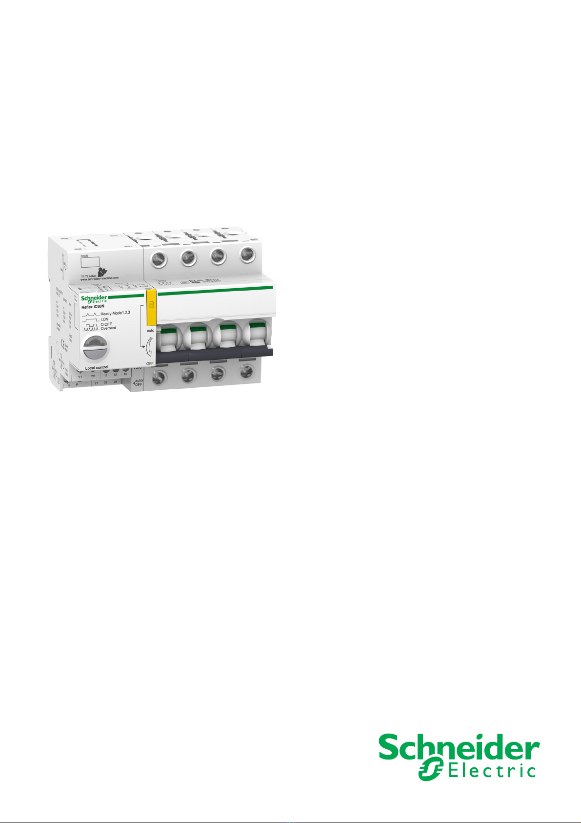
The Reflex iC60 integrated control circuit breaker combines the function for remote control of an
installation and the protection functions of a circuit breaker in a single unit. Reflex iC60 integrated control
circuit breakers are available with 2, 3 and 4 poles.
All Reflex iC60 products have two 230 V AC local controls:
zInput Y1: latched order local control or on edges (depending on operating mode)
zInput Y2: local one-shot closing and opening control
The Reflex iC60 product version with Ti24 enables the Reflex iC60 circuit breaker to interface directly with
a PLC, in order to:
zExecute remote control (input Y3, low level 24 V DC)
zIndicate the position (open/closed) of the circuit breaker’s poles (O/C contacts) or tripping of the circuit
breaker (auto/OFF contacts)
The iMDU auxiliary is used to control the Reflex iC60 circuit breaker at 24/48 V AC/DC.
Catalog numbers of Reflex iC60 circuit breakers
There are 2 families of integrated control circuit breakers (Reflex iC60N and Reflex iC60H) which are
characterized by their breaking capacity.
The composition rule for A9C••••• catalog numbers is as follows:
Example: Catalog number A9C62316 corresponds to a type N, curve C, 3P, 16 A Reflex iC60 integrated
control circuit breaker with Ti24 interface.
Catalog numbers of Reflex iC60N integrated control circuit breakers with Ti24 interface:
Catalog numbers of Reflex iC60N integrated control circuit breakers without Ti24 interface:
Family Reflex iC60N Reflex iC60H
Operating voltage Ue 220 to 240 V 380 to 415 V 220 to 240 V 380 to 415 V
Ultimate breaking capacity Icu 20 kA 10 kA 30 kA 15 kA
Service breaking capacity Ics z63 A rating: 50% Icu
zOther ratings: 75% Icu
All ratings: 50% Icu
Field A9 C • = 5 / 6 • = 1 / 2 / 3 / 4 • = 2 / 3 / 4 •• = A
Meaning Acti 9 range Control 5 = without Ti24
interface
6 = with Ti24 interface
1 = type N, curve B
2 = type N, curve C
3 = type N, curve D
4 = type H, curve B
2 = 2 poles
3 = 3 poles
4 = 4 poles
•• =
10 A/16 A/25 A/
40 A/63 A
Reflex
iC60N
Number of poles
2 P 3 P 4 P
Tripping curves
RatingBCDBCDBCD
10 A A9C61210 A9C62210 A9C63210 A9C61310 A9C62310 A9C63310 A9C61410 A9C62410 A9C63410
16 A A9C61216 A9C62216 A9C63216 A9C61316 A9C62316 A9C63316 A9C61416 A9C62416 A9C63416
25 A A9C61225 A9C62225 A9C63225 A9C61325 A9C62325 A9C63325 A9C61425 A9C62425 A9C63425
40 A A9C61240 A9C62240 - A9C61340 A9C62340 - A9C61440 A9C62440 -
63 A A9C61263 A9C62263 - A9C61363 A9C62363 - A9C61463 A9C62463 -
Reflex
iC60N
Number of poles
2 P 3 P 4 P
Tripping curves
Rating B C D B C D B C D
10 A - A9C52210 - - A9C52310 - - A9C52410 -
16 A - A9C52216 - - A9C52316 - - A9C52416 -
25 A - A9C52225 - - A9C52325 - - A9C52425 -
40 A - A9C52240 - - A9C52340 - - A9C52440 -
63 A - A9C52263 - - A9C52263 - - A9C52263 -

Introduction
A9MA03EN 02/2012 11
Catalog numbers of Reflex iC60H integrated control circuit breakers with Ti24 interface:
Description of optional auxiliaries
The iMDU adapter auxiliary enables the Reflex iC60 integrated control circuit breaker to be used with a
24 to 48 V AC/DC control voltage.
The Vigi iC60 module is used to measure the differential residual current.
Reflex
iC60H
Number of poles
2 P 3 P 4 P
Tripping curves
RatingBCDBCDBCD
10 A A9C64210 A9C65210 A9C66210 A9C64310 A9C65310 A9C66310 A9C64410 A9C65410 A9C66410
16 A A9C64216 A9C65216 A9C66216 A9C64316 A9C65316 A9C66316 A9C64416 A9C65416 A9C66416
25 A A9C64225 A9C65225 A9C66225 A9C64325 A9C65325 A9C66325 A9C64425 A9C65425 A9C66425
40 A A9C64240 A9C65240 A9C66240 A9C64340 A9C65340 A9C66340 A9C64440 A9C65440 A9C66440
Product designation Catalog number Description
iMDU A9C18185 24 or 48 V AC/DC – 230 V AC adapter module
Product designation Catalog number Description
Vigi iC60 A9V••••• and A9Q••••• Differential residual current detection module

Introduction
12 A9MA03EN 02/2012
Description
Reflex iC60 integrated control circuit breaker without Ti24 interface
A 230 V AC power supply terminal block
B Y1/Y2 control input terminal block
C Terminal block for the circuit breaker pole position (open/closed) indication contact
D Terminal block for the circuit breaker trip indication contact
F Isolated terminals
G Circuit breaker pushbutton for manual control and selection of operating mode
H Circuit breaker operating state LED
I Resetting handle for circuit breaker
Reflex iC60 integrated control circuit breaker with Ti24 interface
A 230 V AC power supply terminal block
B Y1/Y2 control input terminal block
C Terminal block for the circuit breaker pole position (open/closed) indication contact
D Terminal block for the circuit breaker trip indication contact
E Ti24 interface terminal block
F Isolated terminals
G Circuit breaker pushbutton for manual control and selection of operating mode
H Circuit breaker operating state LED
I Resetting handle for circuit breaker
F
Local control
auto
OFF
Reflex iC60N
A
B D C
F
Ready-Mode1.2.3
I. ON
O. OFF
Overheat
1211 14
21 22 24
O/C
auto/
OFF
Y1 Y2
NP
A9C5pppp
Mode 1
Mode 2
H
G
I
Local control
auto
OFF
Reflex iC60N
1211 14
21 22 24
O/C
auto/
OFF
Y1 Y2
NP
FCD
A
B
FE
Ready-Mode1.2.3
I. ON
O. OFF
Overheat
A9C6pppp
Mode 1
Mode 2
Mode 3
H
G
I

Installation
14 A9MA03EN 02/2012
Assembly
Introduction
A Vigi iC60 optional auxiliary can be added to the Reflex iC60 integrated control circuit breaker.
Assembly procedure with Vigi iC60 A9V••••• auxiliary
Step Action
1 Pull out the padlocking device
2 Check that the handle is in OFF position (circuit breaker open)
3 Remove the blanking plate on the right-hand side of the Reflex iC60 circuit breaker using a screwdriver
4 Assemble the Vigi iC60 auxiliary with the Reflex iC60 circuit breaker
5 Place the assembly on the DIN rail and push in the 5 locking clips
6 Push the padlocking device back in
Local control
auto
OFF
Reflex iC60N
A9Vppppp
Ready-Mode1.2.3
I. ON
O. OFF
Overheat
1211 14
21 22 24
O/C
auto/
OFF
Y1 Y2
NP
5
5
auto
OFF
Reflex iC60N
1
Ready-Mode1.2.3
I.ON
O.OFF
Overheat
2
Vigi iC60 25 A
Vigi iC60 40 A A9Vppppp
Vigi iC60 63 A
auto
OFF
Reflex iC60N
Ready-Mode1.2.3
I. ON
O. OFF
Overheat
auto
OFF
6
Reflex iC60N
Ready-Mode1.2.3
I. ON
O. OFF
Overheat
3
4

Installation
A9MA03EN 02/2012 15
Assembly procedure with Vigi iC60 A9Q••••• auxiliary
Step Action
1 Pull out the padlocking device
2 Check that the handle is in OFF position (circuit breaker open)
3 Remove the blanking plate on the right-hand side of the Reflex iC60 circuit breaker using a screwdriver
4 Assemble the Vigi iC60 auxiliary with the Reflex iC60 circuit breaker
5 Place the assembly on the DIN rail and push in the 3 locking clips
6 Push the padlocking device back in
auto
OFF
Reflex iC60N
1
Ready-Mode1.2.3
I.ON
O.OFF
Overheat
2
Vigi iC60 25 A
Vigi iC60 40 A A9Qppppp
auto
OFF
Reflex iC60N
Ready-Mode1.2.3
I. ON
O.OFF
Overheat
4
3
1211 14
21 22 24
O/C
auto/
OFF
Local control
auto
OFF
Y1 Y2
NP
Reflex iC60N
A9Qppppp
Ready-Mode1.2.3
I. ON
O. OFF
Overheat
5
5
auto
OFF
6
Reflex iC60N
Ready-Mode1.2.3
I. ON
O. OFF
Overheat

Installation
16 A9MA03EN 02/2012
Connection
Safety Instructions
Connection Blocks
The following diagram shows the 6 connection blocks of a Reflex iC60 integrated control circuit breaker
with Ti24 interface.
A 230 V AC power supply terminal block
B Y1/Y2 control input terminal block
C Terminal block for the circuit breaker pole position (open/closed) indication contact
D Terminal block for the circuit breaker trip indication contact
E Ti24 interface terminal block
F Isolated terminals
DANGER
HAZARD OF ELECTRIC SHOCK, EXPLOSION, OR ARC FLASH
zWear appropriate personal protective equipment and follow the standard electrical safety
precautions.
zOnly qualified electricians who have read the relevant instructions are authorized to install this
equipment.
zNEVER work alone.
zDisconnect all current and voltage sources before carrying out visual inspections, testing or
maintenance work on this equipment. Always assume that all circuits are live until they have been
de-energized, tested and labeled. Pay particular attention to the design of the power supply circuit.
Take account of all power supply sources, including in particular feedback possibilities.
zBefore closing the covers and doors, carefully inspect the working area to ensure that no tools or
other items have been left inside the equipment.
zTake care when removing or replacing panels. In particular, make sure that they do not touch live
busbars. To minimize the risk of injury, avoid handling panels.
zIf this equipment is to remain in good working order it must be handled, installed and operated
correctly. Failure to comply with basic installation instructions may lead to injury and may damage
the electrical equipment or other property.
zNEVER shunt an external fuse/circuit breaker.
zThis equipment must be installed inside a suitable electrical cabinet.
Failure to follow these instructions will result in death or serious injury.
Local control
auto
OFF
Reflex iC60N
1211 14
21 22 24
O/C
auto/
OFF
Y1 Y2
NP
FCD
A
B
FE
Ready-Mode1.2.3
I. ON
O. OFF
Overheat

Installation
A9MA03EN 02/2012 17
The following diagram shows the 5 connection blocks of a Reflex iC60 integrated control circuit breaker
without Ti24 interface.
A 230 V AC power supply terminal block
B Y1/Y2 control input terminal block
C Terminal block for the circuit breaker pole position (open/closed) indication contact
D Terminal block for the circuit breaker trip indication contact
F Isolated terminals
Description of the Terminals
A230 V AC power supply terminal block
BY1/Y2 control input terminal block
CTerminal block for the circuit breaker pole position (open/closed) O/C indication contact
DTerminal block for the circuit breaker trip auto/OFF indication contact
F
Local control
auto
OFF
Reflex iC60N
A
B D C
F
Ready-Mode1.2.3
I. ON
O. OFF
Overheat
1211 14
21 22 24
O/C
auto/
OFF
Y1 Y2
NP
Terminal Function
N Neutral
P Phase
Terminal Function
Y1 Mode 1: local closing control on rising edge and opening control on falling edge
Mode 2: local opening control on rising edge, latched at high state (state = 1) to inhibit Y2
Mode 3: centralized control enabled (Y1 = 1) or centralized control inhibited (Y1 = 0)
Y2 Mode 1: local one-shot closing and opening control
Mode 2: local one-shot closing and opening control
Mode 3: local one-shot closing and opening control
Terminals Contact Function
11–12 NC (normally closed) Circuit breaker state: closed
11–14 NO (normally open) Circuit breaker state: open
Terminals Contact Function
21–22 NC (normally closed) Circuit breaker state: closed
21–24 NO (normally open) Circuit breaker state: open following tripping

Installation
18 A9MA03EN 02/2012
Einterface I/O terminal block Ti24
FIsolated terminals
Connection Characteristics
Connection Diagrams
Minimum power recommended for the Reflex iC60 integrated control circuit breaker power supply
according to the number of poles:
Terminal Function
0 V 0 V DC power supply
O/C Indication of the position (open/closed) of the poles of the circuit breaker:
zO/C closed: the contacts are closed.
zO/C open: the contacts are open.
auto/OFF Indication of tripping of the circuit breaker:
zauto/OFF closed: the circuit breaker handle is in the auto position.
zauto/OFF open: the circuit breaker handle is in the OFF position.
Y3 Mode 1: centralized closing control on rising edge and opening control on falling edge
Mode 2: centralized closing control on rising edge and opening control on falling edge
Mode 3: centralized closing control on rising edge and opening control on falling edge
24 V 24 V DC power supply
Terminals Function
0.5...25 A Power
32...63 A Power
Item Terminal block Tightening
torque
Stripping
length
Wire size
Solid Flexible Flexible with
ferrule
2 cables
A Power supply
(230 V AC)
1 N.m 10 mm 1...10 mm² 1...6 mm² 0.5...4 mm² ≤2 x 1.5 mm²
≤2 x 2.5 mm²
B Inputs Y1/Y2
C Output O/C 0.7 N.m 8 mm 1...2.5 mm² 0.5...2.5 mm² 0.5...1.5 mm² ≤2 x 1.5 mm²
D Output
auto/OFF
E Ti24 interface – 10 mm 0.5...1.5 mm² –
F 0.5...25 A 2 N.m 14 mm 1...25 mm² 0.5..0.16 mm² ≤5 x 1.5 mm²
≤3 x 2.5 mm²
≤2 x 1.5 mm² +
≤1x2.5mm²
32...63 A 3.5 N.m 1...35 mm² 0.5...25 mm² ≤5 x 4 mm²
≤3 x 6 mm²
≤2 x 4 mm² +
≤1 x 6 mm²
NOTICE
RISK OF MALFUNCTION
zIn three-phase applications, use the same phase to connect the power supply and inputs Y1 and Y2.
zKeep to the recommended minimum power for the Reflex iC60 integrated control circuit breaker
power supply.
Failure to follow these instructions can result in equipment damage.
Number of poles Power supply
2P 350 VA
3P 700 VA
4P 1350 VA

Installation
A9MA03EN 02/2012 19
The following diagram illustrates connection of a Reflex iC60 integrated control circuit breaker, without
Ti24 interface, used in mode 1 or 2:
The following diagram illustrates connection of a Reflex iC60 integrated control circuit breaker, with Ti24
interface, used in mode 1, 2 or 3:
The following diagram illustrates connection of a Reflex iC60 integrated control circuit breaker, with Ti24
interface, used in mode 3:
NP
PN
Y1 Y2
11 12 14
O/C
21 22 24
auto/OFF
A9C5pppp
NP
PN
24 V c
PLC
24 V auto/OFF O/C 0V
0 V
In In
Out
Y3
Ti24
Y1 Y2
11 12 14
O/C
21 22 24
auto/OFF
A9C6pppp
24 V c
0 V
In
Out
NP
PN 24 V O/C 0V
Y3
Ti24
Y1 Y2
11 12 14
O/C
21 22 24
auto/OFF
A9C6pppp
auto/OFF
In
PLC

Installation
20 A9MA03EN 02/2012
Supplying the Control Inputs Using an iMDU Auxiliary
The Y1/Y2 control inputs on Reflex iC60 integrated control circuit breakers operate at 230 V AC voltage.
An iMDU auxiliary is used to control a Reflex iC60 integrated control circuit breaker via a 24/48 V AC/DC
output.
The following diagram illustrates connection of the control inputs on a Reflex iC60 integrated control
circuit breaker using iMDU auxiliaries:
The catalog number for the iMDU auxiliary is available in the relevant section (see page 11).
NP
Y1 Y2
Reflex iC60
24/48
Vac/dc
iMDU
P Y1/Y2
24/48
Vac/dc
24/48
Vac/dc
iMDU
P Y1/Y2
24/48
Vac/dc
NL1
O/C
auto/OFF
21 22 24 11 12 14
This manual suits for next models
1
Table of contents
Popular Power Tools manuals by other brands

Scantool
Scantool TSX 1060 manual

Woodstock
Woodstock Shop Fox W1684 instruction manual

Grizzly
Grizzly G0656 owner's manual

Meister
Meister MFW300-1 Translation of the original instructions

Ingersoll-Rand
Ingersoll-Rand IQ V20 Cordless Impactool W5000 Series user manual

RODCRAFT
RODCRAFT RC3100 Operator's manual

Rose electronics
Rose electronics XTREME FLAT 8 owner's manual

King Tony
King Tony 9TY511-12A-B Operation manual

Geberit
Geberit FlowFit 691.032.00.1 user manual

Metabo
Metabo BS 14.4 Li Original instructions

Cooper Instruments & Systems
Cooper Instruments & Systems DTW 750 user guide

Chicago Pneumatic
Chicago Pneumatic MS 695 Safety and operating instructions