Safety and Responsibility 9
Designated Use
REFUsol 100K
982059/02
2020-11
EnglishDeutsch
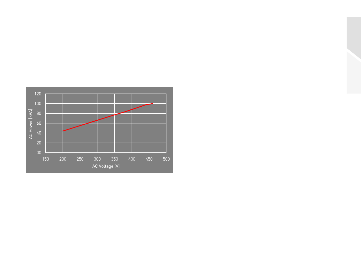
2.4 Designated Use
The REFUsol 100K, is a solar inverter, which trans-
forms the direct current generated by the PV generator
(photovoltaic modules) into alternating current and can
feed it into mains supply.
The REFUsol 100K complies with protection class
IP65 (ConnectionBox: IP54) and can be used indoors
and outdoors.
The REFUsol 100K is only intended for use with the
corresponding central or decentral ConnectionBox.
2.5 Requirements for Electricians
The activities described in this manual require basic
knowledge of the electrical system, the associated
technical terms and the relevant technical rules. To
ensure safe use, these activities may therefore only be
carried out by an appropriate specialist or a trained
person under the supervision of a specialist.
A skilled person is a person who, on the basis of his
professional training, his knowledge and experience as
well as his knowledge of the relevant regulations, can
assess the work assigned to him, recognize possible
dangers and take suitable safety measures.
2.6 General Safety Instructions
▷Observe the valid regulations for accident preven-
tion and environmental protection.
▷Observe the safety regulations and regulations of
the country in which the product is used.
▷Only use products in technically perfect condition.
▷Observe all notes on the product.
▷Persons installing, operating or maintaining prod-
ucts must not be under the influence of drugs or
medication.
▷Use only accessories and spare parts approved by
REFU Elektronik GmbH in order to exclude a per-
sonal hazard due to unsuitable spare parts.
▷Observe the technical data and ambient conditions
specified in the manual.
▷Do not put the product into operation until it has
been determined that it complies with country-spe-
cific rules, regulations, safety regulations/certifi-
cates and application regulations.