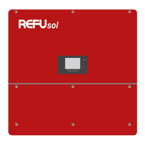
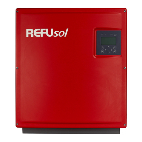
REFU REFUsol 48K-UL User manual

Pos: 2/ Inverter Manuals/Einga ngsteil/Titelblätter/Titel blattR EFUsol 48K-UL @ 3\mo d_1480066630896_ 0.docx@ 2 6170 @ @ 1
Installation and Operating Manual
REFUsol 48K-UL
English
REFU Elektronik GmbH
843 / 844 Series (with and without AFCI)
REFU Elektronik GmbH No. 982018, Version 1.0 2017-03
Pos: 3/ Inverter Manuals/Einga ngsteil/Rechtliche Hinw eise vor Inhaltsverzeichnis/ WRU L@ 2\ mod_14697798044 48_641.docx @ 23434 @ 2222 @ 1

2 REFUsol 48K-UL REFU Elektronik GmbH
Copyright
This manual and the information included therein are the property of REFU Elektronik GmbH.
No part of this manual is to be reproduced or copied without the express written permission of REFU
Elektronik GmbH. Any unauthorized use of this manual is strictly forbidden. Copyright © 2017 REFU
Elektronik GmbH. All rights reserved.
Disclaimer and Limitation of Liability
The information contained in this manual is subject to change by REFU Elektronik GmbH without prior
notice. REFU Elektronik GmbH makes no warranty of any kind whatsoever, either expressed or implied, with
respect to the information contained herein. REFU Elektronik GmbH shall not be liable in damages, of
whatever kind, as a result of the reliance on or use of the information contained herein.
Product Usage Statement
WARNING
Read this entire manual and all other publications pertaining to the work to be
performed before you install, operate, or maintain this equipment. Practice all plant
and product safety instructions and precautions. Failure to follow instructions can
cause personal injury and/or property damage. If the equipment is used in a manner
not specified by the manufacturer, the protection provided by the equipment may be
impaired. All personnel who work with or who are exposed to this equipment must
take precautions to protect themselves against serious or possibly fatal bodily
injury.
REFU Elektronik GmbH provides information on its products and associated
hazards, but it assumes no responsibility for the after-sale operation of the
equipment or the safety practices of the owner or user.
NEVER DEFEAT INTERLOCKS OR GROUNDS.
Trademarks
REFUsol is a registered trademark of REFU Elektronik GmbH.
All other trademarks or registered trademarks are the property of their respective owners.
Feedback from Customers
The technical editor of REFU Elektronik GmbH has carefully developed this handbook on the basis of
research-based document design principles. Suggestions for improvements are always welcome. Please
send your comments regarding the content, structure or format of these operating instructions to:

REFU Elektronik GmbH REFUsol 48K-UL 3
=== Ende der Liste für Te xtmarke Inhalt1 ===
Pos: 97 /InverterM anuals/Kont akt/UL @ 2\mod_147393 2446547_641.doc x@ 24936 @ 1 @ 1
=== Ende der Liste für Te xtmarke Inhalt3 ===
Pos: 6/g emeinsame Doku mente/Table of Contents @ 2\mod_ 1455109417638_641. docx@ 17 984 @ @ 1
Table of Contents
1About these Operating Instructions 6
1.1 Symbols and Markup............................................................................................................................... 6
1.2 Warning Notices....................................................................................................................................... 7
1.2.1 Categories of Warning Notices ........................................................................................................... 7
1.2.2 Information........................................................................................................................................... 7
2Safety Information 8
2.1 Intended Use ............................................................................................................................................ 8
2.2 Safety Guidelines ..................................................................................................................................... 8
2.2.1 Rules for Safe Installation and Operation.......................................................................................... 8
2.3 Personal Safety........................................................................................................................................ 8
2.3.1 Suitable Personal Protective Equipment ........................................................................................... 8
2.3.2 Medical and First Aid Treatment ........................................................................................................ 9
2.3.3 Safety Equipment Requirements........................................................................................................ 9
2.3.4 Electrical Safety................................................................................................................................... 9
2.3.5 Wiring Requirements......................................................................................................................... 10
2.3.6 Grounding Requirements.................................................................................................................. 11
2.3.7 Heat Hazard ....................................................................................................................................... 11
2.3.8 Lockout and Tagout Requirements .................................................................................................. 12
2.4 Acronyms and Frequently Used Terms................................................................................................ 12
2.5 Interpreting Product Labels.................................................................................................................. 13
2.6 Product Compliance .............................................................................................................................. 14
2.6.1 Safety and EMC Directives and Standards....................................................................................... 14
3Description of Device 15
3.1 Operating Mode...................................................................................................................................... 15
3.2 Features of REFUsol 48K-UL................................................................................................................ 16
3.3 External Dimensions ............................................................................................................................. 17
3.4 Block Diagram ....................................................................................................................................... 17
3.5 System Block Diagram.......................................................................................................................... 18
3.6 Control Panel ......................................................................................................................................... 18
3.7 Internal Data Logger.............................................................................................................................. 19
4Installation 20
4.1 Assembly Site Requirements................................................................................................................ 20
4.2 Transport................................................................................................................................................ 21
4.3 Storage................................................................................................................................................... 21
4.4 Check Delivery ....................................................................................................................................... 22
4.5 Unpacking the Device ............................................................................................................................ 22
4.6 Installation ............................................................................................................................................. 24
4.7 Device Connectors................................................................................................................................. 26
4.8 Grounding............................................................................................................................................... 27

4 REFUsol 48K-UL REFU Elektronik GmbH
4.9 Residual Current Protection................................................................................................................. 27
4.10 DC and AC Wiring Feedthrough ............................................................................................................ 28
4.11 Grid Line Impedance.............................................................................................................................. 28
4.12 DC Connection of the Solar Generator ................................................................................................. 29
4.13 DC and AC Terminal Connections......................................................................................................... 31
4.14 Interface Port RS485 ............................................................................................................................. 33
4.15 Ethernet Interface Connection.............................................................................................................. 34
5Commissioning 35
5.1 Switching on the Device at Initial Start-up........................................................................................... 35
5.2 Switching on the Device after Replacement ........................................................................................ 36
5.3 Disconnecting Device Power................................................................................................................. 37
5.4 Setting the Country Code and the Menu Language ............................................................................. 37
5.4.1 Set Country Code/Grid Guideline...................................................................................................... 38
5.4.2 Accepting the Country Code.............................................................................................................. 38
5.5 Device Start............................................................................................................................................ 39
5.6 Control Panel ......................................................................................................................................... 40
5.7 Graphical Display................................................................................................................................... 40
5.8 Energy Yield Data Display...................................................................................................................... 41
5.9 Standardized Energy Yield Data Display............................................................................................... 41
5.9.1 Input of Standardized Data................................................................................................................ 42
5.10 Menu Structure...................................................................................................................................... 43
6Configuration 44
6.1 Changing the Menu Language .............................................................................................................. 44
6.2 Limitation of the Power Output............................................................................................................. 44
6.3 Monitoring with REFUlog ...................................................................................................................... 45
6.4 REFUset PC Configuration Tool......................................................................................................... 45
6.5 Communication via Ethernet................................................................................................................. 46
6.5.1 Automatic Setting via DHCP.............................................................................................................. 46
6.5.2 Manual Setting................................................................................................................................... 46
6.6 Communication via RS485..................................................................................................................... 47
6.7 Portal Monitoring................................................................................................................................... 48
6.8 Sending Config....................................................................................................................................... 48
6.9 Portal Test Function .............................................................................................................................. 48
7Operating the Arc Fault Detection Unit (ADU) 49
7.1 General Description............................................................................................................................... 49
7.2 Normal Operation of the Arc Fault Detection Unit .............................................................................. 49
7.2.1 To Operate the ADU in Normal Conditions....................................................................................... 49
7.3 Responding To An Arc Fault.................................................................................................................. 49
7.3.1 To Resolve an Arc Fault..................................................................................................................... 50
8Troubleshooting 51
8.1 Self-Test Error Message.................................................................................................................... 51
8.2 Transient Failure ................................................................................................................................... 51

REFU Elektronik GmbH REFUsol 48K-UL 5
8.3 Faults...................................................................................................................................................... 51
8.4 Fault Acknowledgement........................................................................................................................ 51
8.5List of Error Messages .......................................................................................................................... 51
9Options 57
9.1 Irradiation and Temperature Sensor.................................................................................................... 57
9.1.1 Inverter Sensor Interface.................................................................................................................. 57
9.1.2 Sensor Type Si-13TC-T-K Cable....................................................................................................... 57
9.1.3 Assembling of the Sensor Plug......................................................................................................... 58
9.1.4 Connection of the Sensor at the Solar Inverter ............................................................................... 58
9.1.5 Configuration ..................................................................................................................................... 59
9.2 External Turn Off Signal........................................................................................................................ 60
9.2.1 Overview............................................................................................................................................. 60
9.2.2 Function.............................................................................................................................................. 60
9.2.3 Configurations.................................................................................................................................... 61
9.2.4 Configuration ..................................................................................................................................... 62
10 Maintenance 63
10.1 Maintain the Inverter............................................................................................................................. 63
11 Decommissioning 64
11.1 Remove Inverter..................................................................................................................................... 65
11.2 Package Inverter.................................................................................................................................... 65
11.3 Disposal.................................................................................................................................................. 65
12 Technical data 66
12.1 Inverter................................................................................................................................................... 66
12.2 Sensor..................................................................................................................................................... 68
12.3 Efficiency Measurement REFUsol 48K-UL (843P048.000) .................................................................. 69
12.3.1 Efficiency Graph............................................................................................................................. 69
12.3.2 Efficiency Curves ........................................................................................................................... 69
12.4 Efficiency Measurement REFUsol 48K-UL (844P048.000) .................................................................. 70
12.4.1 Efficiency Graph............................................................................................................................. 70
12.4.2 Efficiency Curves ........................................................................................................................... 70
12.5 Temperature Derating Curve................................................................................................................ 71
13 Contact 72
Pos: 7/ Inverter Manuals/Zu dies erBe dienungsanleitung/ WRU L@ 2\ mod_1469783255 159_641.docx @ 23449 @ 122332 @ 1

6 REFUsol 48K-UL REFU Elektronik GmbH
1About these Operating Instructions
These operating instructions form part of the product.
Important Safety Instructions
Read the operating instructions carefully before installing and using the product.
Save these operating instructions. This manual contains important instructions for the REFUsol solar
inverter that shall be followed during installation and maintenance of this unit.
Keep the operating instructions readily available with the device for the entire service life of the
product.
Provide all future users of the device access to the operating instructions.
Additional information on device options and troubleshooting is available at www.refu-sol.com.
1.1 Symbols and Markup
Prerequisite
One-step instruction
1.
Multiple-step instruction
Bulleted list
Highlighting
Highlighting within a text
Result

REFU Elektronik GmbH REFUsol 48K-UL 7
1.2 Warning Notices
1.2.1 Categories of Warning Notices
This symbol represent important notes concerning potential harm to people, this
unit, or associated equipment. This manual includes this symbol in Danger,
Warning, and Caution boxes to identify specific levels of hazard seriousness.
DANGER
DANGER indicates an imminently hazardous situation that, if not avoided, will
result in death or serious injury. DANGER is limited to the most extreme
situations.
WARNING
WARNING indicates a potentially hazardous situation that, if not avoided, could
result in death or serious injury.
CAUTION
CAUTION indicates a potentially hazardous situation that, if not avoided, could
result in minor or moderate injury.
NOTICE
NOTICE is used for property-damage-only accidents.
1.2.2 Information
Pos: 8/ Inverter Manuals/Sicher heitshinweise/Einleit ung/Sicherheitshin weise @ 1\mod_140534 4856819_641.doc x@ 7351 @ 1 @ 1
Note:
A notice describes information, which is important for the optimum and
cost-effective operation of the equipment.

8 REFUsol 48K-UL REFU Elektronik GmbH
2Safety Information
Pos: 9/ Inverter Manuals /Sicherheitshin weise/Bestimmungsge mäße Verwend ung/866/867 @ 1\m od_14047408478 08_641.docx @ 6749 @ 2 @ 1
2.1 Intended Use
The REFUsol 48K-UL inverter, also referred to in these operating instructions as the inverter, is a solar
inverter, which transforms the direct current generated by the PV generator (photovoltaic modules) into
alternating current and feeds this to the public power supply network.
The inverter is manufactured according to the rules and current state of technology and takes into account
the valid EU, IEC and UL guidelines respectively.
The inverter fulfils the requirements according to protection class IP 65 / NEMA 4 and can be used indoors
and outdoors.
Any other use is not considered to be a designated use. The manufacturer accepts no liability for damages
resulting from this.
Pos: 10 /Inverter Manuals/ Sicherheitshi nweise/Einleitung/U Ls pecifics afety guideli nes/WR UL @ 2\mo d_146978425747 0_641.docx @ 23466 @ 2 @ 1
2.2 Safety Guidelines
Commissioning and operation of this unit must be carried out by qualified personnel. Qualified personnel
includes licensed electricians, service personnel, and authorized operators who have read and fully
understood all of the technical information and the safety instructions contained in this manual.
Review the following information before attempting to install and operate the product.
2.2.1 Rules for Safe Installation and Operation
Please note the following rules:
Do not attempt to install or operate this equipment without proper training.
Ensure that this unit is properly grounded.
Ensure that all cables are properly connected.
Verify that input line voltage and current capacity are within specifications before turning on the
power supplies.
Use proper electrostatic discharge (ESD) precautions.
Always be careful around this equipment.
Never remove the upper inverter lid.
Safe operation requires correct transport, storage, assembly, installation, and operation.
Pos: 11 /Inverter Manuals/ Sicherheitshi nweise/Qualifikation d es Personals/WR UL @ 2\ mod_146978 4561182_641.doc x@ 23494 @ 2 @ 1
2.3 Personal Safety
2.3.1 Suitable Personal Protective Equipment
Whenever possible, interaction with this unit should be performed under de-energized conditions.
If interaction with this unit is necessary while it is energized, always ensure that any personnel entering a
safety zone wear appropriate Personal Protective Equipment (PPE) for the specific job to be performed.
Identification of appropriate PPE is the responsibility of the PV system operator and shall be determined in
accordance with NFPA 70E and/or local jurisdictional requirements.

REFU Elektronik GmbH REFUsol 48K-UL 9
2.3.2 Medical and First Aid Treatment
Personnel working in and around operating power generation equipment should be trained in arc flash
hazard, fire extinguisher selection and use, first aid, cardiopulmonary resuscitation (CPR), and automated
external defibrillator (AED) use when each is applicable.
2.3.3 Safety Equipment Requirements
Authorized service personnel performing operations on this unit should have the following minimum safety
equipment available:
Consult NFPA 70E, or applicable local standards, for PPE requirements on switch gear operating
Electrical hazard footwear (ANSI Z41/Z85 rated)
Lockout Tagout (LOTO) Kit
Appropriate meter to verify the circuits are safely de-energized (1000 VAC and DC rated, minimum)
Any other equipment as applicable to your operation as required by national, state, and local
regulations
Pos: 12 /Inverter Manuals/ Sicherheitshi nweise/Produkt anforderungen (Co mpliance)/Electricial S afety/Einleitung/WR U L @ 2\mod_14697 89747475_641. docx@ 23540 @ 3 @ 1
2.3.4 Electrical Safety
DANGER
Risk of electrical shock. High voltages are present in the inverter cabinet.
Put DC disconnect into OFF position when working on the unit.
To completely deenergize the DC input conductors, if necessary invoke an
additional equipment disconnecting means, or remove the fuses from an
external combiner box.
Wait 15 minutes to discharge high voltage before working of the inverter.
Put AC disconnect into OFF position.
DANGER
Risk of electrical shock
All electrical installations should be accomplished in accordance with
applicable national or local standards.
DANGER
Risk of electrical shock
Before connecting the inverter to the electrical utility grid, your utility
company must grant approval. Only qualified electricians should make the
connection to the utility grid.

10 REFUsol 48K-UL REFU Elektronik GmbH
Pos: 13 /Inverter Manuals/ Sicherheitshi nweise/Produktanfor derungen (Com pliance)/Wiring/843 844 UL @ 3\mod_148 0064841771_641.d ocx @ 26146 @ 3 @ 1
2.3.5 Wiring Requirements
Inverters must be installed by qualified individuals and in accordance with all appropriate regulations, local
building, and electric codes. Consult NEC 690 (USA), CEC Section 50 and 64 (Canada), for additional
information.
You must meet the AC overcurrent protection requirements according to the following table when wiring the
inverters:
Power Level
Breaker Size
48 kW
80 A
Important
Maximum AC overcurrent protection for all models is 80 A.
Pos: 14 /Inverter Manuals/ Sicherheitshi nweise/Produktanfor derungen (Com pliance)/Wiring/WR UL @ 3 \mod_14865 64676801_641.doc x @2 7714 @ 3 @ 1
Wiring Information
Important
You must use National Electrical Code (ANSI/NFPA 70) wiring methods.
All wiring methods and materials shall be in accordance with the National Electrical Code
ANSI/NFPA 70, as well as all state and local code requirements.
Installations in Canada should be in accordance with the Canadian Electrical Code (CEC) or
applicable local standards.
When sizing conductors and conduits for connection to the inverters, both shall be in accordance
with the National Electrical Code ANSI/NFPA 70, as well as state and local code requirements.
The AC and DC power connections in the inverter should be securely fastened.
AC overcurrent protection for the utility interconnect (grid-tied) must be provided by the installers as
part of the inverter installation.
Use only conductors with a minimum insulation rating of 90 °C (194 °F).
This equipment is intended to be installed as part of a permanently grounded electrical system per
the NEC or local standards.
Wiring Connections
The inverter is connected to the utility grid at the AC terminals. The inverter is configured for 480 VAC, three-
phase output with separate neutral.
Important:
Electromagnetic radiation of the unit is equal to standard household
equipment.
No special precautions are required for people with pacemakers, metallic
implants, or hearing aids.

REFU Elektronik GmbH REFUsol 48K-UL 11
The inverter is connected to the DC photovoltaic array with two DC block terminal inputs rated for max.
1000 V.
Pos: 15 /Inverter Manuals/ Sicherheitshi nweise/Produktanfor derungen (Com pliance)/Grounding/WR UL @ 2\mod_1 469791595882_6 41.docx @ 23564 @ 3 @ 1
2.3.6 Grounding Requirements
Determine the appropriate grounding method with the responsible authority having jurisdiction.
System grounding, if required by Section 250 of the National Electrical Code, ANSI/NFPA 70, is the
responsibility of the installer.
The photovoltaic system grounding shall be installed per the requirements of Section 690.41 through
690.47 of the National Electrical Code, ANSI/NFPA 70, and is the responsibility of the installer.
Grounding the PV Modules
The PV frames require an equipment grounding conductor (EGC) per NEC requirements.
The inverter is a transformerless inverter. For this reason, it has no galvanic isolation. Neither the
positive (+) pole nor the negative ( ) pole of the modules connected to the inverter can be grounded.
Only the array frame/racking and modules frame must be grounded, or only the PV module frame
and racking must be grounded.
Insulation resistance detection (ground fault detection): Since the inverter is connected to
ungrounded PV arrays, it has an insulation resistance detection circuit that measures the DC
insulation resistance between the PV array inputs and earth ground prior to starting.
An Isolation Monitor Interrupter (IMI) is used to limit ground fault and backfeed current to the array
and the Protective Earth connection. This device limits shock hazards by restricting the ability of the
unit to connect to the grid when the system exceeds the limits stated in UL 1741. Additionally, the PV
array IMI monitors for ground fault current as required by UL 1741. If a ground fault occurs, the
inverter will shut off and will not restart until the fault has been cleared.
Grounding the AC Circuit
A protective earth feedthrough terminal block is available in the AC connection area. The gauge of the AC
grounding conductor must be sized in accordance with Table 250.122 of the NEC.
Important
Establish an AC ground connection to the protective earth ground (PE)
terminals before connecting to the grid.
Pos: 16 /Inverter Ma nuals/Sicherheitshi nweise/Produkt anforderungen (Com pliance)/Heat Hazard/ WR UL @ 2\mod_146 9791914275_641. docx @ 23576 @ 3 @ 1
2.3.7 Heat Hazard
The cabinet surface and heat sink can reach temperatures up to 75 °C (167 °F).
WARNING
Risk of burn. The inverter components can become extremely hot during
normal operation.
Use caution when working around the heat sink area.
Pos: 17 /Inverter Manuals/ Sicherheitshi nweise/Lockout and T agoutR equirements/WR U L @ 2\mod_146 9792427195_641. docx @ 23600 @ @ 1

12 REFUsol 48K-UL REFU Elektronik GmbH
2.3.8 Lockout and Tagout Requirements
To prepare the inverter for maintenance or troubleshooting, you must deenergize and isolate the AC and the
DC interface energy sources before working on the unit.
Pos: 18 /InverterM anuals/Sicher heitshinweise/Acro nyms and frequently used Ter ms/WR @ 2\mod_1422895020 309_641.docx @ 13535 @ 2 @ 1
2.4 Acronyms and Frequently Used Terms
Term
Description
A/D
Analog to digital conversion
ADU
Arc Fault Detection Unit
AFCI
Arc Fault Circuit Interrupter
AFI
Insulation fault
ANSI
American National Standards Institute
BEMS
Building energy management system
CFM
Cubic feet per minute
CPUC
California Public Utilities Commission
Derating
A controlled reduction in performance, usually dependent on component
temperatures.
DHCP
Dynamic host configuration protocol
DNS
Domain name service
DSP
Digital signal processor
DVI
Digital video interface
EMI
Electromagnetic interference
ESD
Electrostatic discharge
GEC
Grounding electrode conductor
GFDI
Ground fault detector interrupter
IEEE
Institute of Electrical and Electronics Engineers
IGBT
Insulated gate bipolar transistor
IP
Internet protocol
Islanding
Islanding occurs when the inverter continues to feed power to a de-energized
AC main circuit.
LOTO
Lockout Tagout
MCM
1000 circular mils utilized in wire sizing
MPPT
Maximum power point tracking
NTP
Network time protocol

REFU Elektronik GmbH REFUsol 48K-UL 13
Term
Description
NFPA
National Fire Protection Association
PCB
Printed circuit board
PLL
Phase lock loop
PPE
Personal protective equipment
PV
Photovoltaic
PVM
PV monitoring
PVM Sync
Software application used to query inverters
PWM
Pulse width modulation
Remote
enable/disable
The inverter system can be remotely turned on or off. The inverter restarts after
a five minute countdown
RMS
Root mean squared
SCADA
Supervisory control and data acquisition. A computer system that monitors and
controls infrastructure or facility-based processes.
Set point
Inverter is operating and delivering power at defined parameters.
String
A group of series-connected PV modules.
UL
Underwriter's Laboratory
UTC
Universal time coordinate. Also known as Greenwich mean time.
VAC
Voltage alternating current
VDC
Voltage direct current
VOC
Open-circuit voltage
Pos: 19 /Inverter Manuals/Sich erheitshinweise/W arnhinweise im oder am Gerät/WR UL @ 2\mod _1469784791580_64 1.docx @ 23506 @ 2@ 1
2.5 Interpreting Product Labels
The following labels may appear on your unit:
General warning sign
Hazardous voltage

14 REFUsol 48K-UL REFU Elektronik GmbH
Hot surface
Refer to manual for more information
Pos: 20 /Inverter Manuals/ Sicherheitshi nweise/Produktanfor derungen (Co mpliance)/Safety and EMC Dir ectives and Sta ndards/WR UL @ 2\ mod_1469785608968_ 641.docx @ 2351 8@ 2 @ 1
2.6 Product Compliance
The following sections include information about unit compliance and certification, including the conditions
of use required to be in compliance with the standards and directives.
2.6.1 Safety and EMC Directives and Standards
Certain options of this unit have been tested for and comply with the following electromagnetic compatibility
(EMC) and safety directives and standards and industry guidelines.
Important
This equipment must be installed and used in accordance with the Conditions of Use described in this
manual. If this equipment is expanded, modified, or installed into a larger system, the user is responsible to
guarantee the compliance of the overall system. If this equipment is used with external components, the
user must ensure that the Safety and EMC requirements are not violated.
Safety Directives and Standards
UL 1741 Inverters, Converters, Controllers and Interconnection System Equipment for Use With
Distributed Energy Resources (2010)
IEEE 1547 Standard for Interconnecting Distributed Resource with Electric Power Systems
FCC Part 15 Class B conducted emissions
National Electrical Code
Can be installed in compliance with National Electrical Code 2008, 2011, and 2014 Editions Article
690 Solar Photovoltaic Systems
Certified to Puerto Rico Electric Power Authority (PREPA)
The inverter is designed to be compliant with UL 1741, UL 1998, FCC Part 15 (Class A and B),
IEEE 1547, and CSA C22.2.
Utility Interconnection
Voltage and Frequency Variation
IEEE 1547.2 Standard for Interconnecting Distributed Resource with Electric Power Systems
Prevention of Islanding
IEEE 1547.1a Standard for Conformance Test Procedures for Equipment Interconnecting
Distributed Resources with Electric Power Systems was used for the test method; IEEE 1547
paragraph 4.4 was used for timing requirements.
Pos: 21 /Inverter Manuals/ Gerätebeschrei bung/Überschrift/G erätebeschreibu ng @ 1\mod_141 0956962695_641. docx @ 7842 @ 1 @ 1

REFU Elektronik GmbH REFUsol 48K-UL 15
3Description of Device
Pos: 22 /InverterM anuals/Ger ätebeschreibung/Fun ktionsprinzip/WR UL @ 3\m od_1486632569265 _641.docx @ 27734 @ 2@ 1
3.1 Operating Mode
The REFUsol 48K-UL transforms the direct current generated by photovoltaic (PV) modules into alternating
current and feeds this into the public grid.
Fig.
1
: How it works: a grid-connected PV system with photovoltaic inverter
1
PV modules
2
Solar string combiner box (depending on authority having jurisdiction AHJ or
utility company)
3
REFUsol photovoltaic inverter
4
Fuse switch disconnector or circuit breaker
5
Grid protection (if required by authority having jurisdiction AHJ or utility company)
6
Isolation transformer is required for medium-voltage network
7
Low or medium-voltage AC grid

16 REFUsol 48K-UL REFU Elektronik GmbH
Pos: 23 /Inverter Manuals/ Gerätebeschrei bung/Merkmale/ 840 842 843 844 @ 1\ mod_141139584766 0_641.docx @ 7977 @ 2@ 1
3.2 Features of REFUsol 48K-UL
The REFUsol 48K-UL inverter is a transformer-less, three-phase solar inverter, which has a particularly
high efficiency at any operating point.
Heat is dissipated only by convection. The internal temperature control prevents the device from exceeding
the permissible ambient temperature.
The inverter is designed such that the device does not have to be opened for assembly and connection work.
The inverter provides communication interfaces for RS485 and Ethernet. The communication protocol is
Modbus and Sunspec compliant.
An illuminated graphical display shows the development of the feed-in power and other operating data in a
clearly arranged manner. An 8-key control panel below the display also provides excellent control and
navigation convenience. Based on its design in protection class IP 65, the inverter can be installed at almost
any outside location. The inverter has extensive safety and security features. For details, refer to Technical
Data on page .
Pos: 24 /Inverter Manuals/ Gerätebeschrei bung/Photo/843 8 44@ 3\ mod_148596 7159906_0.docx @ 2 7504 @ @ 1
Pos: 25 /Inverter Manu als/Gerätebeschrei bung/Geräteauß enmaße/843 844 @ 3\ mod_14861399 61147_641.docx @ 27 565 @ 2@ 1

REFU Elektronik GmbH REFUsol 48K-UL 17
3.3 External Dimensions
Fig.
2
: External dimensions
Note
When installing a DC Combiner Box mind that additional space is needed!
Pos: 26 /Inverter Manuals/ Gerätebeschrei bung/Blockschalt bilder/842 843 844 @ 3\ mod_14786945 59337_641.doc x@ 25318 @ 2 @ 1
3.4 Block Diagram
Fig.
3
: Block diagram

18 REFUsol 48K-UL REFU Elektronik GmbH
1) DC switch
2) DC overvoltage protection type 3 (SPD)
3) DC EMC filter
4) DC current measurement
5) Isolation monitoring
6) DC voltage measurement
7) AC current measurement
8) AC grid relays (redundant)
9) AC voltage and frequency measurement
10) AC EMC filter
11) AC overvoltage protection type 3 (SPD)
12) Fault current monitoring, Type 2
13) Protective earth connection
14) Interfaces (Ethernet, RS485, Sensors, remote stop)
Pos: 27 /Inverter Manuals/ Gerätebeschrei bung/System-Bl ockschaltbilder /8438 44 874 876 @ 3\mod_ 1486390857261_6 41.docx @ 27616 @ @ 1
3.5 System Block Diagram
Fig.
4
: System block diagram (exemplarily described on the 48K-UL model)
Pos: 28 /InverterM anuals/Ger ätebeschreibung/Be dienfeld/WR @ 1\mod_141 0957749856_641.d ocx@ 7 880 @ 2@ 1
3.6 Control Panel
The graphical user interface which is integrated on the front of the device and comprises 128 x 64 pixels can
be used to display the development of data, such as the feed-in power or yield. The parameters required are
selected and entered on the 8-key control panel. The control panel is illuminated when a key is pressed and
turns dark automatically.

REFU Elektronik GmbH REFUsol 48K-UL 19
Fig.
5
: Control panel
Pos: 29 /InverterM anuals/Ger ätebeschreibung/Intern erD atenlogger/WR @ 1\ mod_1410957845375 _641.docx @ 7886 @ 2@ 1
3.7 Internal Data Logger
The inverter features an internal data logger that allows measured values to be simultaneously recorded in
the form of parameters. If the storage capacity is full, the oldest data is overwritten. With the default setting
on delivery, the data logger logs 16 measuring channels, which can be displayed an analyzed by REFUlog.
Recording cycle
Storage time
1 minute
2.5 years
2 minutes
5 years
5 minutes
12.5 years
10 minutes
25 years
Pos: 30 /Inverter Manuals/ Installation/Üb erschrift/Installatio n @ 1\mod_14066 17845321_641. docx@ 7502 @ 1 @ 1
Status
LEDs

20 REFUsol 48K-UL REFU Elektronik GmbH
4Installation
Pos: 31 /Inverter Manuals/ Installation/A nforderungen an Mont ageort/842 843 844 @ 3\ mod_147869480 1881_641.doc x@ 25 356 @ 2 @ 1
4.1 Assembly Site Requirements
DANGER
Danger to life due to fire or explosion.
Do not install inverter in areas with risk of explosion.
Do not install inverter on flammable materials. Uphold fire protection class
according to NFPA regulation.
Do not install inverter in areas where easily flammable materials are stored.
Under no circumstances are the cooling fins of the heat sink to be covered.
WARNING
Danger of accident
When installing and servicing, unrestricted and safe access to the devices
must be ensured.
The following requirements of the installation site must be upheld:
Only vertical installation is permitted as otherwise the cooling of the device cannot be guaranteed
(convection cooling).
Prolonged exposure to direct sunlight can cause an internal temperature rise, leading to power
derating of the device. It is recommended to especially avoid easterly or westerly installation
orientations, or to install a sunshade to mitigate the thermal impact of irradiation.
A fixed wall or a metal construction is necessary for installation. The weight of an inverter amounts
up to 75.6 kg (166 lbs). Relevant construction regulations must be observed.
The device is to be mounted at an appropriate distance from combustible materials.
Installation in non-ventilated ended cabinets and enclosures is not allowed because the unit in
operation emits heat.
To allow for the heat dissipation required, keep the following minimum distances from the ceiling
and wall as well as from neighbouring devices:
Table of contents
Other REFU Inverter manuals
Popular Inverter manuals by other brands

Afore
Afore AF3K-DH Installation and operation manual

Austa
Austa Austa-1P6002G Assembly, installation and operation manual

Hoymiles
Hoymiles HM-800 Quick installation guide

Morningstar
Morningstar SUNSAVER SS-6-12V Installation and operation manual

SMA
SMA Sunny Boy SB 700U installation guide

Huawei
Huawei SUN2000-M1 quick guide