Regal REGASENSE RCL40 User manual

Regasense is a part of Regal Components |
Installation Manual
RCL40, RCL41 & RCL41P
Inductive cylinder sensor with
RCL41 & RCL43
Control box

RCL40 & RCL41
Installation manual
Regasense is a part of Regal Components |
Rev. no.
2021_1
2
Introduction
Intended use Used symbols
General attention
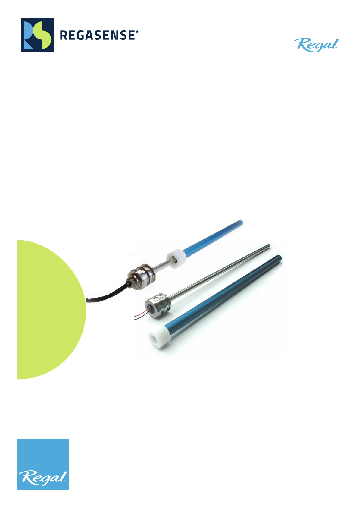
Regasense RCL40/41 sensors are designed to be
installed in hydraulic cylinders with the purpose of
absolute linear positioning.
This manual shall be read together with the data-
sheet.
Safety instructions
Installation and commissioning shall be performed
by technical personnel with appropriate training
and expertise. Whom are trained in the field of
applicable automation technology and installation,
commissioning and/or service operations of the
hydraulic cylinder in use.
If sensor failure or malfunction can cause injury to
person or damage to property, design the system
with additional safety measures to prevent injury or
damage.
Warranty
Regal Components AB grants warranty according to Nordiska leveransbestämmelser (NL09) in applicable
areas or Orgalime S2012. Warranty is not provided for defects due to improper use, storage or excessive
stress on the product.
Warranty is not provided if the product has been modified. No repairs are allowed, in event of sensor mal-
function contact Regal Components AB.
Storage instructions
The sensor must be stored in a dry environment
within the temperature range specified in the da-
tasheet. The sensor shall not be under mechanical
stress that can cause damage to the sensor rod.
Correct storage prior too installation is necessary to
ensure proper function.
Regal Components ABRegal Components AB
Lefflersgatan 1Lefflersgatan 1
SE - 754 50 UppsalaSE - 754 50 Uppsala
SWEDENSWEDEN
+46 (0)18 65 70 00+46 (0)18 65 70 00
www.regal.sewww.regal.se

RCL40 & RCL41
Installation manual
Regasense is a part of Regal Components |
Rev. no.
2021_1
3
Part design
AB
RCL41
RCL41P
RCL40
C
D
E
F
G
Sensor body
A. Sensor header
B. Flange sensor tube
C. Sensor tube
D. Sensor rod
E. PUR cabel output
F. PUR cabel seal
G. Wire output
Product description

RCL40 & RCL41
Installation manual
Regasense is a part of Regal Components |
Rev. no.
2021_1
4
Inductive technology
Regasense RCL40 and RCL41 are inductive linear sensors and the sensors are based on the eddy current
principle. The sensor tube is mounted in the piston of the cylinder and the sensor rod contains a coil. The
sensor will detect the change in inductance that is proportional to how much of the sensor rod is in the
sensor tube.
RCL40 and RCL41 sensors require an RCL-controller to operate. The RCL40 and RCL41 sensor probe can
be used with both variants of controller, so a RCL40-sensor can be used with a RCL41-controller and vise
versa. However the controller is calibrated for a specific stroke length according to the product configura-
tion code.
Scope of delivery
RCL40 or RCL41 sensor with installation accessories:
- 1 pcs support ring
- 1 pcs o-ring
- 2 pcs wave spring washer
- 2 pcs retaining ring
RCL43 controller
RCL41 DIN controller
Sensor and control box are sold separate.
Accessories
Additional accessories, not included in the standard scope of delivery are connectors and cables.
Connectors 6140 is a pressure sealed M12 connector suitable when the installation is not
pressure sealed at the sensor header or/and when the hydraulic cylinder is exposed to extremely harsh
environment requiring a hermetically sealed connector. 6140 suits wire sensors (RCL40) and require
soldering
Connector 6160 is an M12 connector with IP67 protection suitable for applications with pressure seal at
the sensor header. 6160 require no soldering and can be used with sensors with wire connection (RCL40).
When RCL40 is used with 6160 connector, the sensor and connector must be ordered together as the
crimp contacts for the connector are mounted from factory.
Shielded PUR sensor cables with overmolded M12-connector are available in different lengths.
More information on the different connectors and cables are availible in the datasheets.

RCL40 & RCL41
Installation manual
Regasense is a part of Regal Components |
Rev. no.
2021_1
5
Installation of sensor rod
Pre-installation checklist
Make sure that there is no damage to the sensor.
• The sensor rod and tube shall be straight and intact without dents and scratches.
• The sensor header shall be intact.
• Make sure that the electrical connection is in good condition. Wires shall be firmly attached to the back-
side of the header and the cable jacket shall be intact.
• Installation accessories shall be in good condition.
The drilling dimensions in the cylinder must be within specified tolerances. Otherwise there is risk of
malfunction and/or vibration can cause increased wear.
Inspekt the controller so the casing, electronic connection etc. is in good condition, free from damage and
contamination such as liquids or dirt.
Installation of sensor tube
1. Place the wave spring washer in the mounting
hole in the piston.
2. Mount the sensor tube in the piston.
3. Fix the sensor tube with the retaining ring.
1.2±0.04
1.89±0.06
13.95
ø11 ( )
+1.0
-0.5
ø20 ( )
0
-0.3
ø20.955±0.075
Sensortube RCL4X
WAVE SPRING WASHER
RETAINING RING

RCL40 & RCL41
Installation manual
Regasense is a part of Regal Components |
Rev. no.
2021_1
6
1. Mount the o-ring and and back-up ring on the sensor header according to drawing below.
Do not install the senor rod without o-ring and back-up ring. The sensor is not designed for hydraulic
pressure on the backside of the sensor header.
2. Feed the sensor wires or cable thru the drill hole in the cylinder body to the location where the con-
nector or cable gland shall be mounted. This step may vary depending on the design of the cylinder.
Make sure that the wires are free from mechanical stress. Do not pull in the wires/cable to pull the
sensor in place.
3. Mount the sensor firmly in place.
4. Fix the sensor in position:
a. By a M4 flat pointed set-screw. Recommended tightening torgue < 2 Nm. Seal the set screw with
suitable sealing compound. The force from the hydraulic pressure shall apply on the back side of
the sensor head against the cylinder body, the set-screw shall not hold this force.
b. Or use the retaining ring: Place the wave spring washer on the header and then install the retaining
ring.
5. Install the electric connection:
a. RCL41: It is recommended to install RCL41 sensors with a cable gland through the cylinder.
b. RCL40: Connect the wires to a suitible connector. Recommended options is 6140 or 6160 and follow
the instructions in this manual. When RCL40 is used with 6160 connector, the sensor and connector
must be ordered together as the crimp contacts for the connector are mounted from factory.
Installation of sensor rod
19.3±0.05
1.2±0.05
1.9±0.05
ø20 H7 ( )
+0.021
0
ø14 ( )
+0.8
+0.5
BACK-UP RING
O-RING WAVE SPRING WASHER
RETAINING RING
ø20.95
±0.5
1±0.1
25°+5°
0
7.6±0.5
ø20 H7 ( )
+0.021
0
ø14 ( )
+0.8
+0.5
BACK-UP RING O-RING
21.85±0.5
Max. 2 Nm
Installation using set screw Installation using retaining ring

RCL40 & RCL41
Installation manual
Regasense is a part of Regal Components |
Rev. no.
2021_1
7
Installation of connector 6140
1. Place o-ring on connector. Recommended
o-ring: 14 x 1,78 mm NBR70. Not included in
scope of delivery.
2. Cut the sensor wires to suitable length.
3. Place heat shrink tube on the wires.
4. Strip 10 mm of the wires and twist them in pla-
ce in the pins of the connector. See connection
in table below.
5. Solder the joints.
Soldering shall be done by personnel with pro-
per training.
6. Heat the heat shrink wires in place over the
solder joints.
7. Mount the connector in place.
Make sure that the wires are free from mecha-
nical stress.
A A
B
C
D
1
4
3
A. Solder pins
B. O-ring
C. Pin number
Electrical connection 6140
Solder pin Sensor wire Function
1Red lb
3Black Vb
4-

RCL40 & RCL41
Installation manual
Regasense is a part of Regal Components |
Rev. no.
2021_1
8
Installation of connector 6160
6160 connectors can only be used when the
sensor is pressure sealed at the header.
6160 consists of crimp contacts, splice ring, contact
carrier and flange housing. When a RCL40 sensor is
supplied with 6160 connector the crimp contacts is
crimped to the sensor wires from factory.
1. Assemble the crimp contacts with sensor wire
to the splice ring. Connection shown in table
below.
2. Attach the contact carrier.
3. Insert the o-ring into the groove on the hou-
sing.
4. Slide the contact carrier in the housing until
they snap together.
5. Mount the assembled contact to the cylinder.
Recommended tightening torgue 0.3-0.5 Nm.
1
43
2
Pin connection, view plug side
1
2
4
* Note wires is not colour coded in above drawings.
Follow connection in table.
Electrical connection 6160
Connector pin Sensor wire Function
1 Red lb
2 -
3 Black Vb
4 -

RCL40 & RCL41
Installation manual
Regasense is a part of Regal Components |
Rev. no.
2021_1
9
Installation of control box
General information
Both RCL40 and RCL41 sensors can be used with both RCL41 and RCL43 control boxes. Choose the control
box best suited for your application. RCL41 control box is designed for DIN mounting and RCL43 control box
is designed with a sealed aluminium housing. The controller can be placed up to 50 meters away from the
sensor.
Do not supply power to the controller until all wires or cables are connected properly for selected
output. Connect the wires from the sensor, power supply and 0V as well as choosen output configuration
before the power is switched on. Find the schematic under the instructions for each controller.
Always use shielded cables to connect the sensor probe and keep in mind that the cable shield on
RCL41 and RCL41P sensor is connected to the header of the sensor. That may cause damage if there is a
potential difference between the location of the sensor and the grounding point of the cable shield.
To ensure proper EMC-performance:
- The shield of the sensor should be connected to an EMC-cable gland when entering the cabinet in which
the controller is placed.
- The sensor wires inside the cabinet should be kept as short as possible.
- If the cabinet contains EMC-noisy equipment there may be need to EMC-protect the wires and the con-
trol box.

RCL40 & RCL41
Installation manual
Regasense is a part of Regal Components |
Rev. no.
2021_1
10
RCL41 - DIN Controller box
RCL41 DIN Control box terminals
Output conguration options
Connect the control box and sensor according the
schematic figure and choose preffered output con-
figuration.
Output signal and jumper settings
The controllers have two parallel outputs; current
and voltage. There are various options for output
signals depending on how the controller is installed,
if no jumper setting is used the standard factory
setting is:
- Increasing output when the piston is moving away
from the sensor head.
- Terminal 4: 4-20 mA
- Terminal 5: 0-5 V
The output can be configured by adding jumper wi-
res to special terminals on the controller according
to the table.
0-10 V output
It is possible to achieve a 0-10V output from the
system. This require a 500 Ω temperature stable
resistor.
- Place a jumper to select 0-20mA output, see table
and schemtic for instructions.
- The resistor should be installed between terminal
4 and 0V. For best EMC-performance place the re-
sistor at the receiving end of the signal (for instance
at the PLC). By doing this the signal is transmitted
using a noise resistant 0-20 mA signal. The voltage
over the resistor is 0-10V.
Jumper settings
Terminal Terminal Function
15 14 Reverse output
16 14 0-20 mA output
10 12 Gain x2
11 or 12 14 Output -2.5...+2.5 V

RCL40 & RCL41
Installation manual
Regasense is a part of Regal Components |
Rev. no.
2021_1
11
RCL43 - Aluminum Controller box
Connect the control box and sensor according the
schematic figure and choose preffered output con-
figuration.
Output signal and jumper settings
The controllers have two parallel outputs; current
and voltage. There are various options for output
signals depending on how the controller is installed,
if no jumper setting is used the standard factory
setting is:
- Increasing output when the piston is movin away
from the sensor head.
- Terminal 4: 4-20 mA
- Terminal 5: 0-5 V
The output can be configured by adding jumper wi-
res to special terminals on the controller according
to the figure.
0-10 V output
It is possible to achieve a 0-10V output from the
system. This require a 500 Ω temperature stable
resistor.
- Place a jumper to select 0-20mA output, see table
4 and schemtic for instructions.
- The resistor should be installed between terminal
4 and 0V. For best EMC-performance place the re-
sistor at the receiving end of the signal (for instance
at the PLC). By doing this the signal is transmitted
using a noise resistant 0-20 mA signal. The voltage
over the resistor is 0-10V.
80
52
63
75
JUMPER SETTINGS
Standard
4-20mA
0-5V
GAIN=1
Reversed
0-20mA
±2.5V
GAIN=2
RCL43 Control box terminals
Output conguration options

RCL40 & RCL41
Installation manual
Regasense is a part of Regal Components |
Rev. no.
2021_1
12
Comissioning
Check that the controller and sensor are connected properly. Do not supply power to the controller until
all wires or cables are connected properly for selected output.
The sensor probe and the control box are calibrated before shipment. The output should be checked before
and after mounting and is adjustable as described below.
Adjusting / trimming the output
A shorter electrical stroke is possible by adjusting on the controller, maximum 10-15 % on each end. Before
adjusting the output check that the jumper settings are in the right position for the desired output.
Output adjustment using the mid-position
This approach to adjusting the output require a way to move the piston to the center of its movement
(mid-position). I some cases that can be difficult, in that case use adjustment by end positions as described
below.
1. Move the piston rod to its mid-position (half of the desired stroke length).
2. Adjust on the screw ”BALANCE” until 50 % of the output is achieved, for example 12 mA on 4-20 mA
output.
3. Run the piston rod to the desired inner position. Adjust with the screw ”GAIN” until 0 % of the output (or
100 % if reversed).
4. Check that output at outer position is 100 % and repeat if necessary.
Output adjustment using the end positions
If the mid-position is impossible to find accurately the following procedure may be used instead. This way
of output adjustment requires some calculations and a calculator is recommended.
1. Move to inner position and adjust the BALANCE until the target value 0% of output is reached (or as
close to the target value as possible in case it can’t be reached).
2. Move to outer position and note the measured value. Adjust the BALANCE until the signal is half-way
to the target value. Example: target value is 20.00 mA in outer position and the measured value is
19.00 mA. Then adjust the BALANCE screw until the value is 19.5 mA.
3. Still at outer position, adjust the GAIN screw until the target value has been reached.
4. Move to inner position to check that the value still match the target value for that position. If further
adjustment is necessary repeat the steps above until the signal is correct.

RCL40 & RCL41
Installation manual
Regasense is a part of Regal Components |
Rev. no.
2021_1
13
This system is very robust and does usually work for many years of constant operation. However if there is
a problem use this guide to troubleshoot if there is a sensor or controller malfunction.
Note that repairs is not allowed. Contact Regal Components AB in case of malfunction.
Sensor
The sensor is simply put a winded coil. Its DC-resistance, which can be measured with a multimeter tool, is
therefore constant and independent of the position. To check the sensor for error measure the resistance
and check that it is in the range of 9 – 100 Ω. Also check that there is insulation between the sensor wires
and the shield or ground of the system.
Control box
If a system is malfunctioning with a sensor that has been tested according instructions above, then it is
probably the controller that is failing.
It is also possible to check that the communication with the sensor works as it should, but this requires an
oscilloscope. With the system running; attach the oscilloscope parallel to the port 6 and 7 at the control
box, same as the two wires from the probe are attached.
- When measuring the DC voltage it should be around 20-40 mV depending on stroke.
- When measuring the AC voltage it should be around 50-300 mV and 5 kHz.
Troubleshooting
This manual suits for next models
2
Table of contents
Popular Accessories manuals by other brands

MMM
MMM CO2 Series Instructions for use

Orno
Orno OR-CR-235 quick start guide

Outdoor Revolution
Outdoor Revolution Oxygen Speed instructions

LEINER
LEINER WPS Calypso Roll Assembly and operating instructions

Behringer
Behringer F-Control Audio FCA202 operating manual

Honeywell
Honeywell ECO1003 Installation and maintenance instructions