Regulus ETT-F2 User manual

www.regulus.eu
ETT-F2 Heating Element
EN
Installation and Operation Manual
Heating Element with Thermostatic Head,
three-phase model with xed wiring, for utilizing
surpluses from photovoltaic systems.

│2
REGULUS - Heating Element - www.regulus.eu
1 - General Information
1.1 - Application
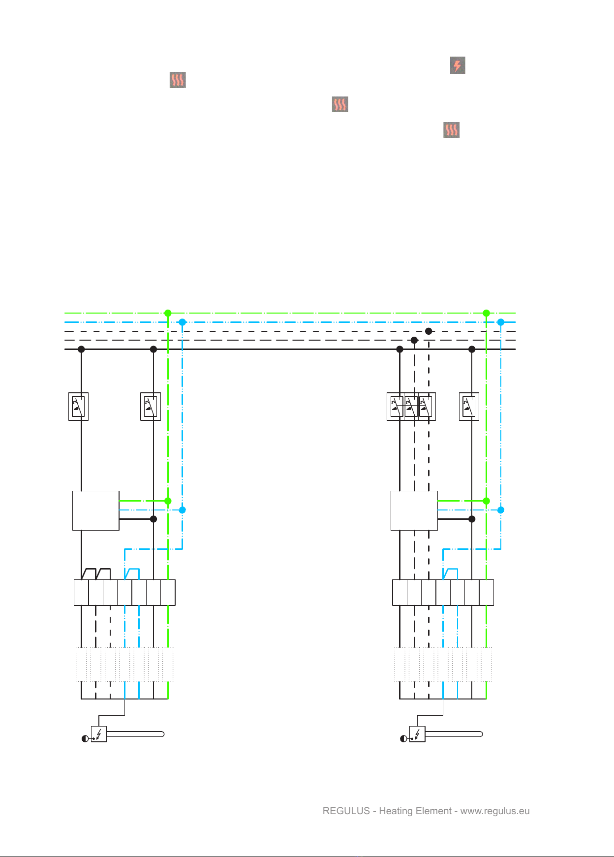
The electric heating element is intended for DHW heating in a hot water storage tank or for heating of heating
water in thermal stores of a heating system. The heating element is designed for utilizing surpluses from sin-
gle- and three-phase PV systems.
1.2 - Installation
Screw the electric heating element into the appropriate connection (socket) equipped with a G 6/4“ F thread so
that the cable gland points vertically downwards. For sealing, we recommend using sealing yarn, hemp, Teon
tape or thread sealant allowing diassembly.
1.3 - Maintenance
Clean the exterior of the heating element with a soft cloth and a suitable detergent. Never use abrasive clea-
ners or solvents.
If the element is used in extra hard water, it is recommended to remove sediments at least once a year.
Disconnect the element from the mains before cleaning. Then drain water from the tank and dismount the hea-
ting element. Scratch the hard deposits on the heating rod with a plastic or wooden spatula and ush with wa-
ter. Be careful not to damage the protective nickel layer on the heating rod. Then reinstall the body according
to this instruction manual, ll the tank with water, air-bleed and pressurize it. Check the threaded connection
for leaks. Finally, re-connect the heating element to the mains.
1.4 - Disposal
IMPORTANT INFORMATION ON PROPER DISPOSAL OF E-WASTE
AS REQUIRED BY THE EC DIRECTIVE 2002/96/EC (WEEE)
Do not dispose of this product as unsorted municipal
waste. Please dispose of this product by returning it to
the point of sale or to your local municipal collection
point for recycling.
Respecting these rules will help to preserve, protect
and improve the quality of the environment, protect
human health and utilize natural resources prudently and
rationally.
The crossed out wheeled bin with marking bar, printed
ether in the Manual or on the product itself, identies that
the product must be disposed of at a recycling collection
site. WEEE Registration Number: 02771/07-ECZ

3 │
REGULUS - Heating Element - www.regulus.eu
2 - Heating Element with Thermostatic
Head, three-phase, xed wiring
2.1 - Technical Description
The electric heating element consists of a nickel-plated heating rod with G 6/4“ M thread, an operating thermo-
stat adjustable between 0±5 °C and 90±3 °C (the lower limit is factory set to circa 15 °C as a frost protection
and the upper limit is set to 60 °C for use in hot water storage tanks) with 5±1.5 °C switching difference, a ma-
nual reset safety capillary thermostat set to 99 °C and +0 °C, -6 °C tolerance, 7× 2.5 mm² power supply cable
and LEDs showing the state of the heating element. The power supply cable is 2 m long.
2.2 - Dimensions
element type output [kW] electrical wiring LN-non-heating end [mm]
L-heating element length [mm]
code
3×230 V ETT-F2-3.0 3 3/N/PE AC 230V 180 370 20232
ETT-F2-5.0 5 3/N/PE AC 230V 180 500 20234
2.3 - Connection to the Mains
The electric heating element shall be wired to a terminal box or electrical switchboard, 3/N/PE AC 400/230V,
xed wiring. The installation shall meet valid rules and standards and shall be done by an authorized person
only.
The wire marked HDO is intended to control the heating element by Ripple control. Should this connection
remained unused, both the centre blue wires (N and HDO) shall be joined together in the terminal box or elect-
rical switchboard.
The wire marked OVLÁDÁNÍ (L) is intended to control the heating element with a heating system controller.
This wire shall be joined with the controller-switched line. In such a case, the temperature set with the thermo-
stat knob shall be higher than that set by the controller. Should this connection remained unused, this wire
shall be joined together with the L1 line in the terminal box or electrical switchboard.

│4
REGULUS - Heating Element - www.regulus.eu
2.5.1 - DHW Heating in a Hot Water Storage Tank
In order to heat water in the hot water storage tank, open the cold water inlet, ll the tank with water and
airbleed it by opening the hot-water tap. Set the thermostat knob to the desired temperature. Both the green
LEDs will be lit on the heating element. As soon as the desired water temperature is reached, the green lamp
marked . will go out. The lit green LEDs show that the heating element is energized and switched on. If the
green LED marked is out, the heating element is switched off by the adjustable thermostat.
It is recommended to set the thermostat knob to 60 °C. This temperature guarantees the best operation of the
heating element and at the same time, it offers:
- protection against Legionella
- cost reduction
- slower deposit formation
2.4 - Wiring Diagram
2.5 - Commissioning, Operation and Possible Faults
WARNING!
THE OUTGOING HOT WATER SHALL NOT BE LEAD THROUGH COMMON PLASTIC
PIPES. THE PIPING SHALL BE RESISTANT TO TEMPERATURE OF 100 °C MIN.
IF PLAIN COMMON PLASTIC PIPING IS USED, ITS SERVICE LIFE IS SIGNIFICANTLY
REDUCED UNDER TEMPERATURES OVER 60 °C. WHEN COMBINED WITH
IMPROPER PIPE FIXING THAT RESTRICTS DILATATION OR EVEN MAKES IT
IMPOSSIBLE, THE PIPE SERVICE LIFE MIGHT BE JUST SEVERAL HOURS!
Prior to commissioning, please make sure the water in direct contact with the heating element does not
exceed the values given in the chart below. The manufacturer bears no responsibility for defects
(e.g. limescale deposits on the heating element) caused by adverse operating conditions.
Table of limit values for total dissolved solids in hot water
Description pH Total dissolved solids (TDS) Ca Chlorides Mg Na Fe
Max. value 6.5-9.5 600 mg/l 40 mg/l 100 mg/l 20 mg/l 200 mg/l 0.2 mg/l
red GREEN GREEN
CONTROL
Ripple control
white

5 │
REGULUS - Heating Element - www.regulus.eu
When the safety temperature is reached, the safety thermostat will cut off the heating element from power
supply. In this state, no LED is lit. The safety thermostat requires manual reset. After the tank cools down, un-
screw the lid on the heating element housing and press the button beneath to reset the thermostat. The green
LED marked is lit and the heating element is ready for use again. Repeated occurrence of this condition
indicates a fault in the heating element. In such a case, disconnect the heating element from the mains and
call a service provider.
2.5.2 - Heating Water for Space Heating in a Thermal Store
Fill the heating system with heat transfer uid, air-bleed it and pressurize to the working pressure. Set the
thermostat knob to the desired temperature.
Should a temperature above 60 °C be set, the limiting spring under the knob shall be removed.
Steps:
- Pull the knob off the shaft,
- There are 2 limit springs inside the knob. Remove the upper one. It is tted in the groove 17 and limits
the adjustable temperature to 60 °C. (Just one spring will remain in the knob, tted in the groove 37. It limits
the min. adjustable temperature to 15 °C)
- Re-t the knob on the thermostat shaft.
This modication will increase the adjustment range to 15 - 90 °C.
Colour Marking Description
Green The heating element is OK, energized and ready for operation
Green The heating element is heating
Two green LEDs will be lit on the heating element. As soon as the desired water temperature is reached, the
green lamp marked . will go out. The lit green LEDs show that the heating element is energized and
witched on.
If the green LED marked is out, the heating element is switched off by the adjustable thermostat.
2.5.3 - Heating Element State during Operation
Heating element state during operation is shown by the LEDs with the following meaning.

│6
REGULUS - Heating Element - www.regulus.eu
3 - Heating Element Wiring Examples
2.5.4 - Possible faults
If the heating element is controlled by a heating controller and while the green LED marked is lit, the
second green LED marked doesn’t light up, then probably the desired temperature set with the knob of the
adjustable thermostat is lower than that set on the controller. Set the thermostat knob to a higher desired tem-
perature.If this does not help and the second green LED marked doesn’t light up, call a service provider.
If the tank gets overheated without using any other heat source (the adjustable thermostat probably does not
turn off the heating element when the set temperature is reached - the green LED marked is on until both
the LEDs go out), call a service provider.
If the heating element shows signs of another defect, disconnect it from the mains immediately and call
a service provider.
PE
N
L3
L2
L1
L-OVLA
L3
L2
L1
L-OV
HDO
N
PE
bílá
červená
N-HDO
TOPNÉ TĚLESO ETT-F2
KABEL - SOUČÁSTÍ TĚLESA
OZNAČENÍ VODIČŮ
SVORKOVNICE
V ROZVADĚČI NEBO
V INSTALAČNÍ KRABICI
NA KONCI KABELU
L1
L2
L3
N
L1
L2
L3
N
PE PE
REGULÁTOR VYUŽITÍ
PŘEBYTKŮ FVE S
PE
N
L3
L2
L1
L-OVLA
L3
L2
L1
L-OV
HDO
N
PE
bílá
červená
N-HDO
VARIANTA S JEDNOFÁZOVOU FVE VARIANTA S TŘÍFÁZOVOU FVE
JISTIČE
SSR RELÉ
VARIANT WITH SINGLE-PHASE
PV SYSTEM
VARIANT WITH THREE-PHASE
PV SYSTEM
CIRCUIT BREAKERS
PV SYSTEM SURPLUS
CONTROLLER WITH
SSR RELAY
TERMINAL BOARD
IN ELECTRICAL
SWITCHBOARD OR
ENCLOSURE
MARKING OF CONDUCTORS
AT THE CABLE END
CABLE - PART OF THE HEATING
ELEMENT
ETT-F2 HEATING ELEMENT
white
red
white
red

7 │
REGULUS - Heating Element - www.regulus.eu
Heating Element with Thermostatic Head,
three-phase, xed wiring
WARRANTY CERTIFICATE
Type: .......................................................................................
Serial number: .......................................................................
Shop: .......................................................... Purchase date: ...............................
1. The warranty period is 24 months from the date of purchase.
2. The product will be installed and commissioned by a competent company or a person
trained by the manufacturer.
3. When claiming warranty, this Warranty Certicate must be submitted together with the
purchase receipt.
4. The warranty is valid only when the technical conditions set by the Manufacturer,
installation manual and instructions in the documentation and on the product itself are
maintained.
5. The warranty does not cover defects caused by external conditions or improper opera-
tion conditions, defects caused by usual wear and tear, further when the product is not
used in compliance with its purpose and when the defect was caused by mechanical
damage, improper handling, tampering by a third person, improper installation, improper
stocking, natural disaster etc.
COMMISSIONING
Company: ………………….......................………….
Date: ………………........................................……..
Rubber stamp print and signature of the installer:
WARRANTY CONDITIONS

©2023 We reserve the right to errors, changes and improvements without prior notice.
REGULUS spol. s r.o.
E-mail: [email protected]
Web: www.regulus.eu
v1.0-08/2023
Table of contents
Other Regulus Heater manuals
Popular Heater manuals by other brands

DeLonghi
DeLonghi DRAGON 4 Instructions for use

Livington
Livington SNBHTR UK Instructions for use

Detroit Radiant Products
Detroit Radiant Products PH Series manual

Acova
Acova Z23010 operating instructions

EQUATION
EQUATION HELLA User and maintenance manual

Dimplex
Dimplex BFH24R Installation and operating instructions