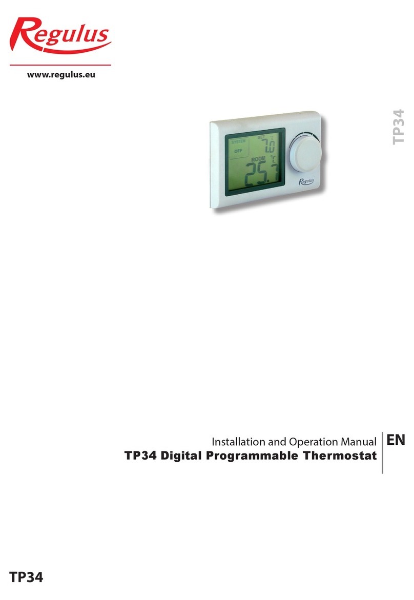
Regulus TP34 RF User manual

www.regulus.eu
TP34 RF
TP34 RF
EN
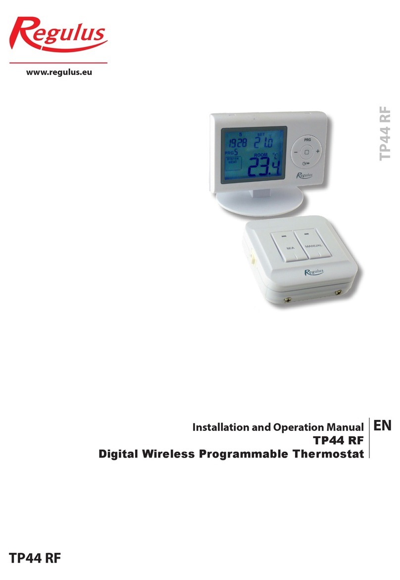
Installation and Operation Manual
TP34 RF
Digital Wireless Programmable Thermostat

1. Description
The wireless digital thermostat is suitable to control temperature in a living room and is very easy to use. It
allows you to control heating or cooling when the room temperature is lower or higher than set by the user.
Installation is very easy thanks to the step-by-step instructions.
IMPORTANT: Installation of the equipment must be performed by a trained specialist. The user manual
is intended for authorized operators.
IMPORTANT: Please read the instructions carefully before installation and follow the instructions
provided when using the thermostat.
Recommendation regarding batteries
• Use only batteries of the specied type.
• Make sure that you insert the batteries as marked in the appropriate compartment. Inserting batteries
with reverse polarity can damage the thermostat.
• Do not mix batteries of dierent types, e.g. alkaline with zinc-carbon batteries or old ones with new
ones.
• If you know that the thermostat will not be used for a long time, remove the batteries to prevent damage
to the thermostat by leakage.
Recommendations regarding installation and use of the thermostat
• This thermostat is intended for indoor use only (rooms, garages, verandas). Do not place it outdoors, do
not expose it to rain.
• Do not place it in high humidity areas.
• It should be installed on an inner wall, about 1,5 m above the oor, located where room temperature
changes can be felt thanks to freely circulating air.
• Do not install above a heat source (a TV set, heater, fridge etc.) or to places where it may be exposed to
direct sunshine, draught, radiation from other devices.
• This thermostat can control only one device. Connecting several devices in cascade or in series (e.g. a
heater and fan) does not guarantee its proper functioning.
• Turn o the power before connecting any equipment.
• Be extremely careful when connecting the equipment and power; improper connection or insucient
shielding of electrical cables can damage the equipment and endanger your safety.
Note: The manufacturer disclaims any liability for damage caused by improper installation or use of the device
contrary to the instructions.
2. Specifications (code 17169)
Transmitter (Thermostat)
1. Programmable: no
2. Displayed temperature range: 0-40 °C (in 0.1 °C increments)
3. Adjustable temperature range: 5-35 °C (in 0.5 °C steps)
4. Temperature measurement accuracy: ±1 °C (at 20 °C)
5. Power supply: 2x 1.5A AAA batteries, alkaline (not enclosed)
6. Load: 6(2) A, 230 V
7. Low Battery Indication: When the battery voltage drops below 2.7 volts, the symbol appears.
8. Standby power consumption: 30 μA, backlight ≤5,5 mA
9. Backlight colour: white
10. Dimensions: 120 x 77 x 28 mm (without support)
Transmitter - batteries 2x1,5 V Receiver - 230 V AC
4. Operating Modes
Hold down the control dial for 5 seconds to open the option to select the operating mode. You can select
from the following modes by turning the dial:
HEAT : turn the dial to set the temperature
COOL : turn the dial to set the temperature
OFF (frost protection): heating starts as soon as the room temperature drops below 7 °C
Finally, press the dial to confirm the desired mode or wait for 10 seconds until the mode is accepted.
5. Temperature Settings
1. To increase the temperature, turn the dial to the right (clockwise), then either press the dial or wait for 5
seconds until the value is accepted.
2. To decrease the temperature, turn the dial to the left (anti-clockwise), then either press the dial or wait for
5 seconds until the value is accepted.
6. Temperature Calibration
Hold down the control dial for 5 seconds to enter the selection of operating modes, then hold down
the dial for another 5 seconds to open the temperature calibration option“CAL“ (from -3 °C to +3 °C in
0.5 °C increments) . Turn the dial to the desired value and press to confirm.
Receiver
1. Power supply: 230 V AC, 50 Hz
2. Operating frequency: 868,35 MHz
3. Transmission distance: approx. 100 m in open air
4. Consumption: 6 W
5. Max. load: 6(2) A, 230 V
6. Dimensions: 86 x 86 x 26 mm
Set temperature
Cooling symbol
Heating symbol
Room temperature
Radio signal symbol
Low battery indication
Operation mode
3. LCD Display

7. Backlight
The backlight turns on when the dial is used and turns off after 15 s of inactivity.
8. Battery Replacement
The average battery life is 1 year, but it can be significantly reduced if backlight is often switched on. When the
low battery symbol appears on the display, the batteries need to be replaced.
9. Receiver
Installation and wiring of the receiver
The receiver must be installed on a wall in a place protected from moisture and heat, not far from the boiler.
WARNING! Do not place the receiver under the boiler casing or near hot water pipes as this may
damage its components or impair the wireless (radio frequency) connection. The receiver must be
installed and connected by a qualified professional!
Unscrew the two screws from the receiver base but do not remove them. Then remove the front panel of the
receiver and screw the rear part of the receiver onto the wall near the boiler with the supplied screws.
It is necessary to supply 230 V power to the receiver. This will power the device, but the voltage will not
appear on terminals 1 and 2.
If the device is not in use, it is recommended to switch it o (e.g. in summer).
The receiver controls the boiler or air conditioning via a potential-free relay whose connection points are: 1
(NO), 2 (COM) and 3 (NC).
WARNING! Always take into account the maximum load rating of the receiver and follow the heating /
cooling manufacturer‘s instructions.
The voltage at terminals 1 and 2 depends solely on the system to be controlled, so the cable cross-section
must respect the type of device controlled by the thermostat. The length of the cables does not play any
role, the receiver can be placed near the boiler or far from it, but never under its casing.
If the distance between the transmitter and the receiver is too big, the RF connection may be unreliable.
Install the receiver as close to the thermostat as possible.
Receiver Control
Apply voltage to the receiver. After a few seconds, the wireless (RF) system of the thermostat and receiver
tunes to the operating frequency. To test the system in heating mode, turn the thermostat dial until the set
temperature is 2-3 ° higher than the room temperature. A few seconds later, the thermostat display should
show a symbol indicating that heating is on. At the same time, a red indicator light on the receiver indicates
that the receiver has been commanded by the transmitter (thermostat).
kotel
NL1234
NO COM NC
napájené zařízení
NL1234
NO COM NC
○
○○
○
230 V
230 V
boiler
powered device
For equipment requiring 230V power supply.
Thermostat Wiring Diagrams for Heating:
For equipment requiring potential-free contact.

Pairing the receiver to a transmitter
If the thermostat does not connect with the receiver, it is necessary to pair them. Press the M / A key on the
receiver and hold it for about 10 seconds until the green indicator light flashes. Then remove the rear cover
of the transmitter and hold down the LEARN key on the PCB for 3 s. The green light on the receiver should
stop flashing and go out, indicating that the receiver has recognized the transmitter (thermostat) code. The
code is retained even in the event of a power failure.
Manual receiver control
Press the MANUAL key to separate the thermostat from the receiver. Then the connected boiler or air condi-
tioner can be controlled manually without thermostatic control. This mode is indicated by a steady green
light. Pressing the M/A button turns the boiler on/off. A switched on boiler is indicated by a red indicator
light. Pressing the MANUAL button again exits the manual control and the device returns to automatic
thermostat controlled operation (the green LED goes out).
ON/OFF switch on the receiver
O: OFF
If the thermostat is not needed, it can be turned off simply by the switch located on the left side of the
receiver without removing the cover.
I: ON
The receiver is in normal operation.
Note:
When the thermostat is not needed during a certain period, it is recommended to switch off the receiver as
a protection of both the device and the thermostat and remove the batteries from the thermostat.


©2019 We reserve the right to errors, changes and improvements without prior notice.
REGULUS spol. s r.o.
E-mail: sales@regulus.eu
Web: www.regulus.eu
v1.1-06/2019
Table of contents
Other Regulus Thermostat manuals

Regulus
Regulus TP08 User manual

Regulus
Regulus TZT63 User manual

Regulus
Regulus TP18 LCD User manual

Regulus
Regulus ETT-R User manual

Regulus
Regulus TP 07-01 User manual

Regulus
Regulus Caleon User manual

Regulus
Regulus TP44 User manual

Regulus
Regulus BB1-1000 User manual

Regulus
Regulus TZ33 User manual

Regulus
Regulus RDC Series User manual