Reichert Lensometer LensChek Plus User manual

LensChek™Plus/Pro
Digital Lensometer®
User’s Guide

23
15180-101 Rev. F
15180-101 Rev. F
©2017 AMETEK, Inc.
Reichert, Reichert Technologies, and Lensometer are registered trademarks of Reichert, Inc.
LensChek is a trademark of Reichert, Inc,
AMETEK is a registered trademark of AMETEK, Inc.
All other trademarks are property of their respective owners.
The information contained in this document was accurate at time of publication. Specifications subject to change without notice.
Reichert, Inc. reserves the right to make changes in the product described in this manual without notice and without incorporating those
changes in any products already sold.
ISO 9001/13485 Certified – Reichert products are designed and manufactured under quality processes meeting
ISO 9001/13485 requirements.
No part of this publication may be reproduced, stored in a retrieval system, or transmitted in any form or by any means, electronic, mechanical,
recording, or otherwise, without the prior written permission of Reichert, Inc.
Caution: Federal law restricts this device to sale by or on the order of a licensed physician. Rx only.

23
15180-101 Rev. F
15180-101 Rev. F
Table of Contents
Warnings and Cautions .................................................................................................................................... 4
Symbol Information........................................................................................................................................... 6
Introduction....................................................................................................................................................... 7
Instrument Setup .............................................................................................................................................. 8
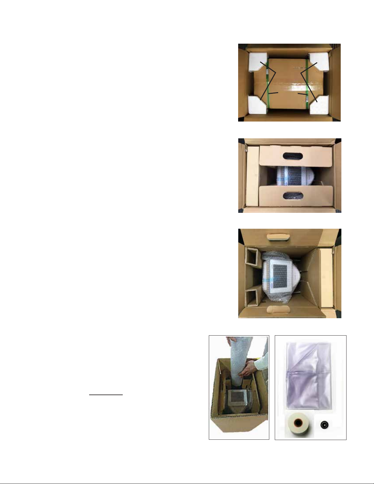
Unpacking Instructions............................................................................................................................... 8
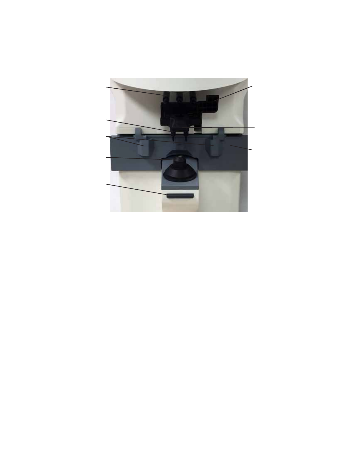
Parts Identification...................................................................................................................................... 9
Initialization............................................................................................................................................... 11
Shutdown of Equipment ........................................................................................................................... 11
Measurement Screen ............................................................................................................................... 12
Description of Measurement Screen.................................................................................................. 12
Icons - Setup and Other Screens....................................................................................................... 13
Instrument Settings ............................................................................................................................ 14
Setup Screens ............................................................................................................................. 14
Practice Screen............................................................................................................................ 17
Communication Settings .............................................................................................................. 18
Time/Date Settings....................................................................................................................... 19
Operation........................................................................................................................................................ 20
Measurement Mode ................................................................................................................................. 20
Lens Placement ................................................................................................................................. 20
Single Lens ........................................................................................................................................ 21
Framed Lens ...................................................................................................................................... 22
Multifocal Lens ................................................................................................................................... 23
Progressive Lens ............................................................................................................................... 24
Contact Lens ...................................................................................................................................... 27
UV Measurement - LensChek Pro ..................................................................................................... 28
PD Measurement - LensChek Pro ..................................................................................................... 28
Marking Lenses ........................................................................................................................................ 29
Lenses With Astigmatism ................................................................................................................... 29
Prism Lenses ..................................................................................................................................... 30
Prism Lenses Measured in X-Y.......................................................................................................... 30
Prism Lenses Measured in B-P.......................................................................................................... 30
Lens Offset......................................................................................................................................... 30
Printing Patient Data ................................................................................................................................ 31
Cleaning & Maintenance ................................................................................................................................ 32
Cleaning ................................................................................................................................................... 32
Main Unit ............................................................................................................................................ 32
Nosepiece Lens ................................................................................................................................. 32
Printer Paper Replacement ...................................................................................................................... 32
Fuse Replacement ................................................................................................................................... 33
Storage..................................................................................................................................................... 33
Power Cord Replacement ........................................................................................................................ 33
Marking Pen Replacement ....................................................................................................................... 34
Troubleshooting.............................................................................................................................................. 35
Specifications ................................................................................................................................................. 36
Guidance &Manufacturer's Declarations ........................................................................................................ 38
Appendix......................................................................................................................................................... 42
RS232C Connection................................................................................................................................. 42
Warranty ......................................................................................................................................................... 43

45
15180-101 Rev. F
15180-101 Rev. F
Warnings and Cautions
Reichert Technologies (Reichert) is not responsible for the safety and reliability of this instrument when:
• Assembly, disassembly, repair or modication is made by unauthorized dealers or persons.
• Instrument is not used in accordance with this User’s Guide.
WARNING: AN INSTRUCTION THAT DRAWS ATTENTION TO THE RISK OF INJURY OR DEATH.
WARNING: DO NOT LOOK DIRECTLY INTO THE UV MEASUREMENT LENS AS IT MAY CAUSE
PERMANENT EYE DAMAGE.
WARNING: UNITED STATES FEDERAL LAW REQUIRE THAT THIS DEVICE BE PURCHASED ONLY BY A
PHYSICIAN OR A PERSON ACTING ON BEHALF OF A PHYSICIAN.
WARNING: THIS INSTRUMENT SHOULD BE USED IN STRICT ACCORDANCE WITH THE INSTRUCTIONS
OUTLINED IN THIS USER’S GUIDE. THE SAFETY OF THE OPERATOR AND THE PERFORMANCE OF
THE INSTRUMENT CANNOT BE GUARANTEED IF USED IN A MANNER NOT SPECIFIED BY REICHERT
TECHNOLOGIES.
WARNING: DO NOT REPAIR OR SERVICE THIS INSTRUMENT WITHOUT AUTHORIZATION FROM
THE MANUFACTURER. ANY REPAIR OR SERVICE TO THIS INSTRUMENT MUST BE PERFORMED BY
EXPERIENCED PERSONNEL OR DEALERS WHO ARE TRAINED BY REICHERT OR SERIOUS INJURY TO
THE OPERATOR MAY OCCUR.
WARNING: MODIFICATIONS TO THIS INSTRUMENT ARE NOT ALLOWED. ANY MODIFICATION TO THIS
UNIT MUST BE AUTHORIZED BY REICHERT OR SERIOUS INJURY TO THE OPERATOR MAY OCCUR.
WARNING: IF THIS INSTRUMENT IS MODIFIED, APPROPRIATE INSPECTION AND TESTING MUST BE
CONDUCTED TO ENSURE CONTINUED SAFE USE OF THIS INSTRUMENT.
WARNING: THE INTERNAL CIRCUITRY OF THE INSTRUMENT CONTAINS ELECTROSTATIC DISCHARGE
SENSITIVE DEVICES (ESDS) THAT MAY BE SENSITIVE TO STATIC CHARGES PRODUCED BY THE
HUMAN BODY. DO NOT REMOVE THE COVERS WITHOUT TAKING PROPER PRECAUTIONS.
WARNING: TO AVOID RISK OF ELECTRIC SHOCK, THIS EQUIPMENT MUST ONLY BE CONNECTED TO A
SUPPLY MAINS WITH PROTECTIVE EARTH OR DAMAGE TO THIS INSTRUMENT AND/OR INJURY TO THE
OPERATOR MAY OCCUR.
WARNING: ENSURE THAT THE VOLTAGE APPLIED TO THE UNIT IS THE SAME AS THE VOLTAGE THAT IS
INDICATED ON THE DATA PLATE OR DAMAGE TO THE UNIT MAY OCCUR.
WARNING: THE INSTRUMENT MUST BE PLUGGED INTO AN OUTLET WITH AN EARTH GROUND. DO
NOT REMOVE OR DEFEAT THE EARTH GROUND CONNECTION ON POWER INPUT CONNECTOR OR THE
UNIT’S POWER CORD OF THIS INSTRUMENT OR DAMAGE TO IT AND/OR INJURY TO THE OPERATOR
MAY OCCUR.
WARNING: THE EQUIPMENT OR SYSTEM SHOULD NOT BE USED ADJACENT TO OR STACKED WITH
OTHER EQUIPMENT AND THAT IF ADJACENT OR STACKED USE IS NECESSARY, THE EQUIPMENT OR
SYSTEM SHOULD BE OBSERVED TO VERIFY NORMAL OPERATION IN THE CONFIGURATION IN WHICH
IT WILL BE USED.
WARNING: THIS INSTRUMENT IS NOT SUITABLE FOR USE IN THE PRESENCE OF FLAMMABLE
ANESTHETIC MIXTURES, SUCH AS OXYGEN OR NITROUS OXIDE.
WARNING: THE USE OF ACCESSORIES OR CABLES OTHER THAN THOSE SPECIFIED, WITH THE
EXCEPTION OF THOSE SOLD BY THE MANUFACTURER AS REPLACEMENT PARTS FOR THE INTERNAL
COMPONENTS, MAY RESULT IN INCREASED EMISSIONS OR DECREASED IMMUNITY OF THE
EQUIPMENT OR SYSTEM.

45
15180-101 Rev. F
15180-101 Rev. F
Warnings and Cautions (continued)
CAUTION: AN INSTRUCTION THAT DRAWS ATTENTION TO THE RISK OF DAMAGE TO THE PRODUCT.
CAUTION: THE INTERNAL CIRCUITRY OF THE INSTRUMENT CONTAINS ELECTROSTATIC DISCHARGE
SENSITIVE DEVICES (ESDS) THAT MAY BE SENSITIVE TO STATIC CHARGES PRODUCED BY THE HUMAN
BODY. DO NOT REMOVE THE COVERS WITHOUT TAKING PROPER ESDS PRECAUTIONS.
CAUTION: DO NOT USE SOLVENTS OR STRONG CLEANING SOLUTIONS ON ANY PART OF THIS
INSTRUMENT AS DAMAGE TO THE UNIT MAY OCCUR. SEE MAINTENANCE SECTION FOR DETAILED
CLEANING INSTRUCTION.
CAUTION: USE OF AMMONIA BASED CLEANERS ON THE LIQUID CRYSTAL DISPLAY (LCD) MAY CAUSE
DAMAGE TO THE DISPLAY. SEE MAINTENANCE SECTION FOR DETAILED CLEANING INSTRUCTION.
CAUTION: MEDICAL ELECTRONIC EQUIPMENT NEEDS SPECIAL PRECAUTIONS REGARDING EMC AND
NEEDS TO BE INSTALLED AND PUT INTO SERVICE ACCORDING TO THE EMC INFORMATION PROVIDED
IN THE ACCOMPANYING DOCUMENTS.
CAUTION: PORTABLE AND MOBILE RF COMMUNICATIONS EQUIPMENT CAN AFFECT MEDICAL
ELECTRICAL EQUIPMENT.
CAUTION: THIS INSTRUMENT IS NOT TO BE USED NEAR HIGH-FREQUENCY EMITTING SURGICAL
EQUIPMENT.
CAUTION: THIS INSTRUMENT IS NOT INTENDED TO BE CONNECTED TO EQUIPMENT OUTSIDE THE
CONTROL OF REICHERT INC. OR MUST BE TESTED TO AN APPLICABLE IEC OR ISO STANDARDS.
CAUTION: DO NOT INSTALL ANY ADDITIONAL SOFTWARE OTHER THAN WHAT WAS SUPPLIED WITH
THIS INSTRUMENT. INSTALLATION OF ADDITIONAL SOFTWARE MAY CAUSE UNEXPECTED OPERATION
RESULTING IN MALFUNCTION OF THIS INSTRUMENT.

67
15180-101 Rev. F
15180-101 Rev. F
Symbol Information
CAUTION
ON / OFF
Alternating Current - Indicates that this instrument operates on alternating current
REF Catalog Number
SN Serial Number
YYYY-MM-DD
Date of Manufacture
Manufacturer
Waste of Electrical and Electronic Equipment
Compliance with Electromagnetic Compatibility Directive 2014/30/EU and Low Voltage
Directive 2014/35/EU
Consult Instructions for Use - Indicates that important operating and maintenance instructions
are included in this User’s Guide
Fragile Contents in Shipping Container - handle with care
Keep Dry - Package shall be kept away from rain
Authorized Representative in European Community
This Way Up - Indicates the correct upright position of package
3063253
Authorization to mark given by Intertek ETL Semko for compliance with electronic standards

67
15180-101 Rev. F
15180-101 Rev. F
Introduction
Congratulations on your purchase of the Reichert Technologies®(hereafter referred to as Reichert®)
LensChek™Plus/Pro Digital Lensometer®.
The LensChek Plus/Pro will provide you with fast, accurate and reliable measurements of eyeglass lenses
for many years. The instrument has an innovative microprocessor controlled lens measurement system that
reduces operator error and provides precise, repetitive measurements for single, multifocal, and progressive
lenses.
The LensChek Pro also allows you to take Pupillary Distance and Ultraviolet Light Transmittance measurements.
This User’s Guide is designed as a training and reference manual for operation, maintenance, and
troubleshooting. We recommend that you read it carefully prior to use and follow the instructions in the
guide to ensure optimum performance of your new instrument. Properly trained eyecare professionals such
as ophthalmologists, optometrists, opticians and eye care technicians should operate this instrument. All
parts of this ME system are suitable for use within the patient environment.
Note: Words in all capital letters reference menu choices.
Note: Words in initial capital letters reference parts shown in the Parts Identication section of this manual.
Also initial capitals are used when referencing menu options on the LCD Screen.
Note: Underlined words reference a specic section of this manual.
Please retain this guide for future reference and to share with other users. For additional copies of this
manual or questions related to the LensChek Plus/Pro, contact your local authorized Reichert Technologies
dealer or contact our Customer Service department directly at:
Tel: 716-686-4500
Fax: 716-686-4555
E-mail: [email protected]
Indications for Use
The LensChek Plus is designed for:
• Measuring single, bifocal, and progressive eyeglass lenses.
• Measuring contact lenses.
The LensChek Pro is designed for:
• Measuring single, bifocal, and progressive eyeglass lenses.
• Measuring contact lenses.
• Measuring pupillary distance.
• Measuring lenses with ultraviolet transmittance.
Contraindications
None.

89
15180-101 Rev. F
15180-101 Rev. F
Instrument Setup
Unpacking Instructions
The LensChek Plus/Pro and its accessories are packaged so as to
protect them from damage during shipment. The outer box holds an
inner box that contains the LensChek Plus/Pro instrument and an
accessory box.
To unpack the LensChek Plus/Pro, follow these steps:
1. Cut the shipping straps and tape on the Outer Box to access the
Inner Box. Refer to Figure SU-01.
2. Remove the Foam Corners from the inside of the box. Refer to
Figure SU-01.
3. Cut the tape and Straps to access the contents of the Inner Box.
Refer to Figure SU-02.
4. Lift up the Cardboard Flaps from the Inner Box to access the unit.
Refer to Figure SU-02.
5. Remove power cords from the box. Refer to Figure SU-03A.
• Power cord* - 120 V (P/N 16290-003) and
Power cord* - 230 V (P/N 15180-003)
6. Remove the Accessory Box. Refer to Figure SU-03.
7. Carefully remove the LensChek Plus/Pro from the box and
remove the protective cover protecting the instrument from
dirt, contaminants and cosmetic damage.
Refer to Figure SU-03.
8. Remove the User's Guide from the bottom of the box.
9. Remove the accessories from the Accessory Box. This box
contains the following accessories: (Note: The Printer Paper
and the Contact Lens Stand can be placed in the Storage
Compartment for safe storage.)
Refer to Figures SU-03A & SU-05.
• Dust cover (P/N 15180-002)
• Printer Paper (P/N 16290-006)
• Contact Lens Stand (P/N 15180-004)
(for measuring contact lenses.)
Optional Accessories: (available separately)
• RS232 Cable (10 ft) - (P/N 13912-409)
• Wireless Dongle Kit - (P/N 15171)
• Replacement Pens (Set of 3) - (P/N 15180-005)
• Replacement Printer Paper (Pack of 5) - (P/N
12441)
Note: If any accessories are missing, please contact
Reichert Technologies at the telephone numbers
listed in the Introduction section of this manual.
Note: Place the packaging materials in a safe storage
location in case you need to transport the unit.
Note: Please read the User’s Guide before operating the
LensChek Plus/Pro so that you will be familiar with
its operation.
* For other country requirements for cords, contact Reichert.
Figure SU-01 Outer Box Open
Outer Box
Inner Box
Foam
Corners
Straps
Figure SU-02 Inner Box Open
Cardboard
Flap
Cardboard
Flap
Figure SU-03 Inner Box Contents
Inner Box
LensChek
Plus/Pro
Accessory Box
Dust
Cover
Printer
Paper
Contact
Lens Stand
Power
Cords
Figure SU-03A Accessories

89
15180-101 Rev. F
15180-101 Rev. F
Instrument Setup (continued)
Figure SU-05 LensChek Plus/Pro Front and Sides
LCD Screen
Control Buttons
Lens Stand
Power Indicator
Lens Table
Data Plate (On Back of LCD Screen)
Communication
Port
Marking Lever
Lens Holder
Memory/Add
Button
Power Switch
Power Inlet
with Fuse
Holder
Printer
Storage
Compartment
5V Power Source
Nose Pads
Parts Identication
LCD Screen: Adjustable screen that can tilt up to
60°. Displays all measurements and functions.
Control Buttons: Pressing these buttons activates/
selects the corresponding icon above them on the
LCD Screen.
Power Indicator: Green LED light that is illuminated
when unit is turned ON. Light blinks when in power
save mode.
Lens Table: This is pulled out when performing
measurements so that a at surface is available to
hold the lenses or frames against while measuring
and marking lenses.
Nose Pads: When measuring framed lenses, the
right or left Nose Pad should be positioned in the
middle of the frames to obtain a PD measurement.
(LensChek Pro only.)
Lens Stand: Where the lens is placed in order to
take a reading.
Power Switch: Use this switch to turn the LensChek
Plus/Pro power ON and OFF.
Marking Lever/Lens Holder: The marking lever
and lens holder are integrated. The marking lever is
pressed down to mark the lens, while the lens holder
is lowered to secure the lens in place.
Memory/Add Button: Stores the measurement
values of the lens when pressed. When measuring
a progressive lens in manual mode, this button is
pressed to set the near and far points.
Printer: Prints out the measurement values.
Data Plate: Displays the input power require-
ments, model name and number, serial number, and
Reichert address. (Located on the back of the LCD
Screen.)
5V Power Source: Connect the power cable for the
Wireless Dongle Kit here.
Communication Port: Attach a cable here to send
patient data to a computer.
Power Inlet: Attach the power cord here.
Storage Compartment: Use this location to store
accessories such as the Contact Lens Stand and
Printer Paper.

10 11
15180-101 Rev. F
15180-101 Rev. F
Parts Identication (continued)
Lens Table
Marking Lever
Lens Stand
Memory/Add Button
Marking Pens
Lens Holder
Figure SU-06 Measurement Area
Lens Holder/Lever
Nose Pads*
Lens Holder Lever:
Use this lever to raise and lower the Lens Holder on the lens.
Marking Lever:
Use this lever to raise or lower the Marking Pens on the lens.
Lens Holder:
Secures the lens to the Lens Stand.
Marking Pens:
Use these pens to place ink marks on the lens.
Lens Stand:
Install this cover on the Nosepiece to measure eyeglass lenses.
Contact Lens Cover:
Install this cover on the Nosepiece to measure contact lenses. Refer to the Contact Lens section of this
manual.
Lens Table:
Adjust this table against the bottom edge of the lens to help position it.
Nose Pads:
The Nose Pads allow for the automatic measurement of the Pupillary Distance (PD). (LensChek Pro only)
Memory/Add Button:
Press this button to manually store measurement values and to perform ADD measurements.
Instrument Setup (continued)

10 11
15180-101 Rev. F
15180-101 Rev. F
Initialization
WARNING: DO NOT APPLY INPUT POWER THAT EXCEEDS THE RATINGS GIVEN ON THE DATA PLATE, OR DAMAGE
TO THE INSTRUMENT MAY OCCUR.
WARNING: CARE MUST BE TAKEN TO ARRANGE THE CABLES FOR THE ACCESSORIES SUCH THAT THEY DO NOT
PRESENT A TRIPPING HAZARD TO THE OPERATOR.
WARNING: POSITION THIS INSTRUMENT SO THAT IT IS NOT DIFFICULT TO OPERATE THE DISCONNECTION
DEVICE (PLUG).
Before turning on the power to the LensChek Plus/Pro, perform the following checks:
• Read the data plate located on the back of the LCD screen. Verify that the available input power to
the LensChek Plus/Pro is within the listed voltage range.
• Connect the power cord to the LensChek Plus/Pro and then connect the other end to the power
source.
• Set the Power switch to the ON position (pushed in on the “I” side).
• Check the operation of the Marking Pens. Verify that the pens do not block the optical path of the
measuring system, which could generate an error message.
• Adjust the LCD Screen for the optimum viewing angle.
• Install the Printer Roller and the Printer Paper as indicated in the Maintenance section of this manual.
Shutdown of Equipment
At any time, the power switch can be set to OFF. The unit does not have a power down sequence. To
terminate operation of the LensChek Plus/Pro, press the ON / OFF switch to the OFF position (O).
Instrument Setup (continued)

12 13
15180-101 Rev. F
15180-101 Rev. F
Measurement Screen
Description of Measurement Screen
Axis Mark
Type of Lens
(Left/Right/Single)
Progressive Lens
Auto-Detect Mode
(Displayed when "Auto
Prog" is set to ON)
Cross
Cursor
Measurement
Setting
Display of Alignment
Condition or Error Message
The functions of the buttons under the monitor correspond to the icons displayed at the bottom of the
screen. At the time of normal measurement, they correspond to the icons shown below.
Clear Icon: Clears the measurement values. (The data stored in memory is also cleared by
selecting this icon.)
S/R/L,R/L Icon: Selects single, left or right lens.
Measurement Selection Icon: Switches measurement mode from single vision lens to
progressive lens.
Setup Icon: Switches to Setup screen.
Print Icon: Prints measurement results.
Output Icon: Outputs data from the RS232C port.
Print and Output Icon: Prints measurement results and outputs data from the RS232C
port.
Instrument Setup (continued)
Figure SU-07 Measurement Screen

12 13
15180-101 Rev. F
15180-101 Rev. F
Instrument Setup (continued)
Icons - Setup and Other Screens
When you open the Setup Screen or the system screens, you will see the following icons for the control
buttons. Refer to Figures SU-8 and SU-9.
Down Icon - Press this icon to move down
the screen or go to a different page.
Figure SU-08 Control Button Icons for
Setup screen
Up Icon - Select this icon to move up the
screen or to a different page.
Left Icon - Select this icon to move left on
the screen.
Right Icon - Select this icon to move right
on the screen.
Enter Icon - Select this icon to enter a com-
mand or make a selection.
Plus Icon - Select this icon to increase a
highlighted number on the screen.
Minus Icon - Select this icon to decrease a
highlighted number on the screen.
Figure SU-09 Control Button Icons for
Date/Time Screen

14 15
15180-101 Rev. F
15180-101 Rev. F
Instrument Setup (continued)
Instrument Settings
Setup Screens
The Setup Screens of the LensChek Plus/Pro displays four pages
of default parameters that you can change to accommodate your
preferences. The current default values are highlighted in blue.
Refer to Figures SU-10, SU-11, SU-12, and SU-13.
Use the UP or DOWN icons to nd a category, then use the
RIGHT or LEFT icons to change the parameter in that category.
You can then scroll to a different category and change that
parameter.
When you are nished, select the ENTER icon (check mark icon)
to save your changes and return to the previous screen.
The rst page of the Setup Screen contains the following cat-
egories:
Cyl Selects sign for Cyl (- /+/ ± ) (The sign set on the measurement screen is reected here.)
Step Selects step to display measurement value (0.25 / 0.12 / 0.01)
Auto Prog. Sets auto detection of progressive lens (On / Off)
Lens Selects lens to be measured. (Glasses / H CL / S CL)
Glasses: Framed lens
H CL: Hard contact lens
S CL: Soft contact lens
Auto Memory Automatically takes a reading when the lens is aligned. The measurements will be stored
on the screen and “Marking OK” will appear, showing that the lens was read. (On / Off)
Lens Switch Sets lens switching function. (S/R/L / R/L)
S/R/L: Single lens/ right lens/ left lens
R/L: Right lens/ left lens
ADD Measure Selects auto/ manual memory of far and near points. (F/N.AT / N.AT / Manual)
F/N.AT: Stores both near and far points automatically
N.AT: Stores only near point automatically
Manual: Stores data manually
PD Measure* Displays the PD measurement (On / Off)
UV Measure* Displays the UV measurement (On / Off)
*These settings available with the LensChek Pro only.
Figure SU-10 Page 1, Setup Screen

14 15
15180-101 Rev. F
15180-101 Rev. F
Instrument Setup (continued)
Instrument Settings (continued)
Setup Screens (continued)
The second page of the Setup Screen contains the following
categories:
Prism Selects display of prism value and unit to be
displayed. (Off / X-Y / P-B)
Off: No display
X-Y: X-Y display
P-B: Prism value - base direction.
Prism(mm) Displays the offset from the optical center in mm
(On / Off)
Abbe Selects Abbe number. (20 / 30 / 40 / 50 / 60)
Ray Selects measurement wavelength. (e / d)
e: measures the e line
d: measures the d line
Output Device Select where the measurement data will go. (Printer / RS232C / Both)
Auto Comm Set to either continuously send data to comm port or not. (Off / On)
Baud Rate Select the baud rate. (115200 / 38400 / 9600)
Prog. Graph Sets display of ADD value and assessment graph on progressive lens measurement
screen. (On / Off)
Graph Print Sets printing of ADD value and assessment graph after measuring progressive lens.
(On / Off)
The third page of the Setup Screen contains the following
categories:
Practice Input the Practice Name as it will appear on
printouts. (Enter Data)
Set ID# Sets the starting point for the Patient Identication
Number (up to 5 digits).
Print ID# Display the Patient ID on the printout. (Off / On)
Display ID# Display the Patient ID on the screen. (Off / On)
Date Format Select how the date is displayed.
(MDY / DMY / YMD)
Date Set the current date.
Time Format Display the time in either 12 hour or 24 hour
format. (12hrs / 24hrs)
Time Set the current time.
Figure SU-11 Page 2, Setup Screen
Figure SU-12 Page 3, Setup Screen

16 17
15180-101 Rev. F
15180-101 Rev. F
Instrument Settings (continued)
Setup Screens (continued)
The fourth page of the Setup Screen contains the following
categories:
Brightness Sets brightness of screen
(7 Preset Settings)
Sleep Selects time to activate sleep mode
(Off / 3min / 5min / 10min)
Note: When the unit goes into sleep mode, the
power light will blink. This is to indicate it is
in sleep mode. Pressing any button will
wake up the unit and turn it back on.
Tone Enables an audible tone to sound when pressing
the buttons. (Off / On)
Language Selects language displayed on screen
(Eng / Fra / Deu / Esp / Por / Ita / Chinese)
Defaults Highlight Reset All and press the Enter icon to change all settings back to defaults.
(Reset All)
Instrument Setup (continued)
Figure SU-13 Page 4, Setup Screen

16 17
15180-101 Rev. F
15180-101 Rev. F
Instrument Setup (continued)
Instrument Settings (continued)
Practice Screen
The Practice Screen allows you to enter a business name or other message that will automatically print
with the patient data.
Creating a Message
1. On the Practice ID screen, press the blue UP,
DOWN, RIGHT, or LEFT icons to highlight the
character that you want to appear in the text
box.
2. Select the ENTER icon. The selected
character will appear in the text box.
Refer to Figure SU-14.
3. Repeat Step 1 and 2 until you finish your
message.
4. When you are finished, highlight DONE and
select the ENTER icon to save your message
and return to the Setup Screen.
5. This Practice ID will now print out with the
patient data when you select YES under
Display ID# in the Setup Screen.
Editing Characters in a Message
1. On the Practice ID screen, use the left and right arrow icons in the main selection area, to
highlight the character in front of the character you want to change in the text box.
2. Use the UP, DOWN, RIGHT, or LEFT icons to highlight a replacement character from the grid,
then select the ENTER icon. The character will be inserted behind the highlighted letter. Refer
to Figure SU-13.
3. Repeat steps 1 and 2 for each character that needs to be changed.
Deleting Characters in a Message
1. On the Practice Screen, use the LEFT, RIGHT, UP, or DOWN icons to highlight the character in
front of the character that needs to be deleted. Select the CLEAR icon, located above the DONE
icon.
2. To erase the entire message and start from the beginning, use the UP, DOWN, RIGHT, or LEFT
buttons to highlight the CLEAR icon, and select it. The entire message will be deleted.
Figure SU-14 ID Screen
Text Box

18 19
15180-101 Rev. F
15180-101 Rev. F
Instrument Setup (continued)
Instrument Settings (continued)
Communication Settings
Page 2 of the Setup menu allows you to set the communication parameters for outputting the measurement
values to an external device.
Figure SU-15 Communication Screen
The measurement values are output by selecting “RS232C” or “Both” in the "Output Device” section on page
2 of the Setup screen.
Note: The output content is same as that of the printout. However, the progressive lens graph is not
outputted.
Output Device: Printer: Enables the LensChek Plus/Pro printer. If you press the Printer Icon on the LCD
Screen, the patient data goes to the LensChek Plus/Pro printer.
RS232C: Enables the RS232C port. If you press the TRANSFER icon on the LCD Screen,
the patient data goes to your computer.
Both: Enables the data to both be transferred to the RS232C port as well as print the
measurement data.
Auto Comm: OFF: Disables Auto Communication.
ON: Enables Auto Communication, which continuously sends patient data to the computer.
Baud Rate: Select a Baud rate of 115200, 38400, or 9600.
Note: If you set “Output Device” to “Printer”, it will disable the Auto Communication feature.
Note: To view the RS232C wiring interface protocol, refer to the Appendix section of this manual.

18 19
15180-101 Rev. F
15180-101 Rev. F
Instrument Setup (continued)
Instrument Settings (continued)
Time/Date Settings
The Date/Time settings allow you to enter the correct time and date for your patient printout and to change
the date and time format.
Figure SU-16 Date/Time Screen
1. To change the Date Format, press the UP or DOWN arrows to reach the Date Format field. Press the
RIGHT or LEFT buttons to select a date format. Refer to Figure SU-15.
Your options include:
M/D/Y - Month, Date, Year
D/M/Y - Date, Month, Year
Y/M/D - Year, Month, Date
2. To change the current date, press the RIGHT or LEFT arrows in the Date field to highlight the date
values (month, day, or year) you want to change. Some of the icons at the bottom of the screen will
change.
3. Press the PLUS (+) or MINUS (-) buttons to change the date values.
4. To change the Time Format, press the UP or DOWN arrows to reach the Time Format field. Press the
RIGHT or LEFT buttons to select a time format. Refer to Figure SU-16.
5. Your options include:
12hrs - Displays the time in AM or PM.
24hrs - Displays the time in 24 hour format.
6. To change the current Time, press the RIGHT or LEFT arrows in the Time field to highlight the time
values (hours or minutes) you want to change. Some of the icons at the bottom of the screen will
change.
7. Press the PLUS (+) or MINUS (-) buttons to change the values.
Defaults
This setup section changes the setting of the device back to the default. Using the RIGHT and LEFT arrows,
highlight RESET ALL if you wish to change the setting back to the default. Press the RETURN icon. A long
tone will sound, indicating the device has been set back to the default settings. Press the Enter icon to exit
the Setup screen.

20 21
15180-101 Rev. F
15180-101 Rev. F
Measurement Mode
The LensChek Plus/Pro allows you to measure single lenses
and framed lenses; bifocal, multifocal, and progressive lenses.
You can also take prism measurements.
The LensChek Pro allows you to perform pupillary distance
(PD) measurements, and check the ultraviolet (UV) light trans-
mittance.
Note: Before you measure a lens, verify that the instrument
lens under the Lens Stand is clean. Use a lens cleaning
cloth or a soft, dry, clean cotton cloth to clean it.
Note: For instructions on using the Marking Pens, refer to the
Marking Lenses section of this manual.
Note: For instructions on placing and measuring contact
lenses, refer to the Contact Lens section of this
manual.
Lens Placement
1. Place the lens (oriented up) on the top of the Lens Stand,
with the bottom edge of the lens facing the Lens Table.
Refer to Figure OP-1.
2. Pull the Lens Table towards the lens so that it touches
the bottom edge of the lens. This ensures a correct axis
orientation.
3. Raise and then lower the Lens Holder Lever to secure the
lens to the Lens Stand.
4. When you are finished, raise the Lens Holder Lever to release the lens.
Operation
Figure OP-01 Place Lens on Lens Stand
This manual suits for next models
1
Table of contents
Other Reichert Laboratory Equipment manuals
Popular Laboratory Equipment manuals by other brands

Kodak
Kodak X-Omat 460 RA Processor installation instructions

Peak Scientific
Peak Scientific Precision Hydrogen installation guide

Grease Thief
Grease Thief Colorimeter user manual

Renfert
Renfert Safety Burner eco Series manual

Christ
Christ Touch-itsCE OEM glass 7 instruction manual

Sarstedt
Sarstedt LC 6 instruction manual