Reichert XCEL 455 User manual

XCEL®455
Slit Lamp
User’s Guide

©2014 AMETEK, Inc.
Reichert, Reichert Technologies, and Xcel are registered trademarks of Reichert, Inc.
AMETEK is a registered trademark of AMETEK, Inc.
All other trademarks are property of their respective owners.
The information contained in this document was accurate at time of publication. Specifications subject to change without notice. Reichert, Inc.
reserves the right to make changes in the product described in this manual without notice and without incorporating those changes in any products
already sold.
ISO 9001/13485 Certified – Reichert products are designed and manufactured under quality processes meeting ISO 9001/13485 requirements.
No part of this publication may be reproduced, stored in a retrieval system, or transmitted in any form or by any means, electronic, mechanical,
recording, or otherwise, without the prior written permission of Reichert, Inc.
Caution: Federal law restricts this device to sale by or on the order of a Physician or Practitioner.

3
15140-101 Rev. C
Warnings and Cautions ................................................................................... 4
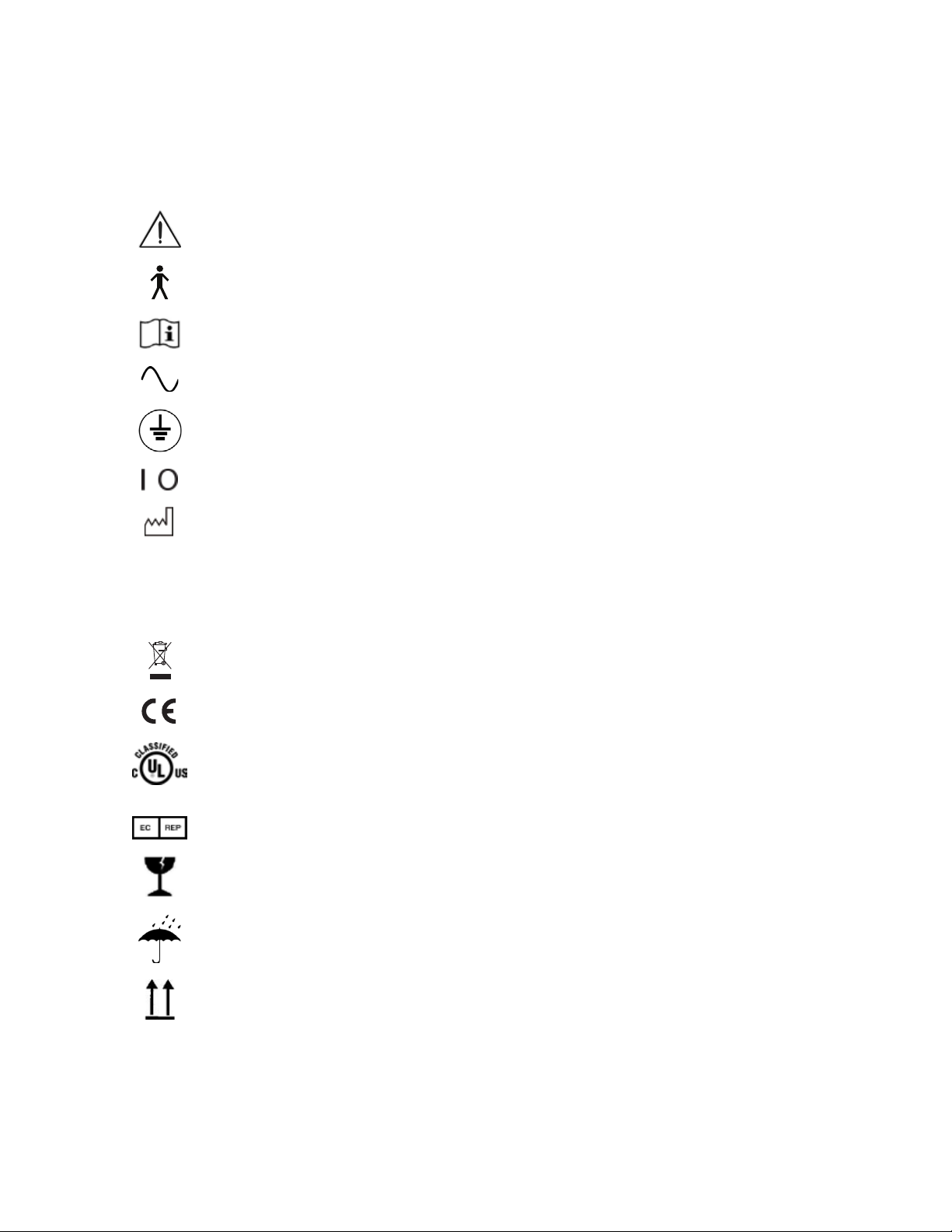
Symbol Information.......................................................................................... 6
Introduction...................................................................................................... 7
Indications for Use..................................................................................... 7
Contraindications....................................................................................... 7
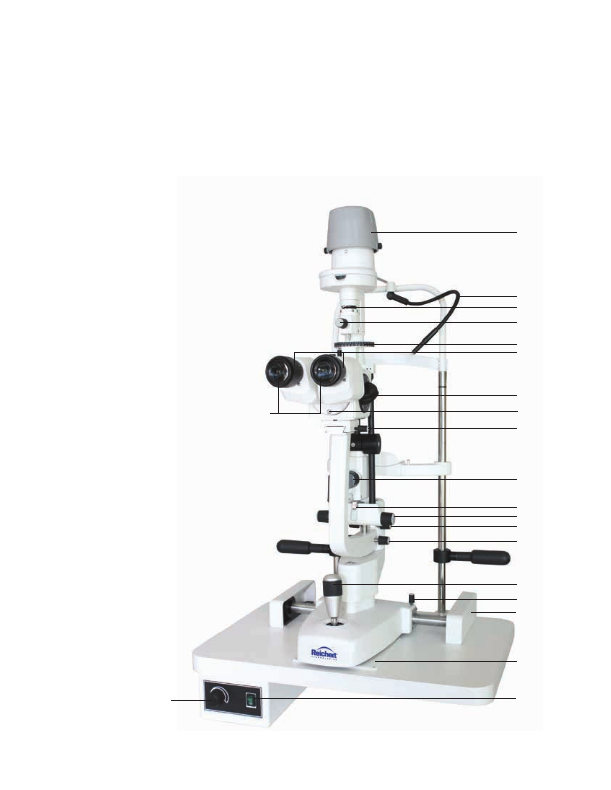
Features & Functions ...................................................................................... 8
Parts Identication ..................................................................................... 8
Xcel 455 Package Contents ...................................................................... 8
Accessories ............................................................................................... 8
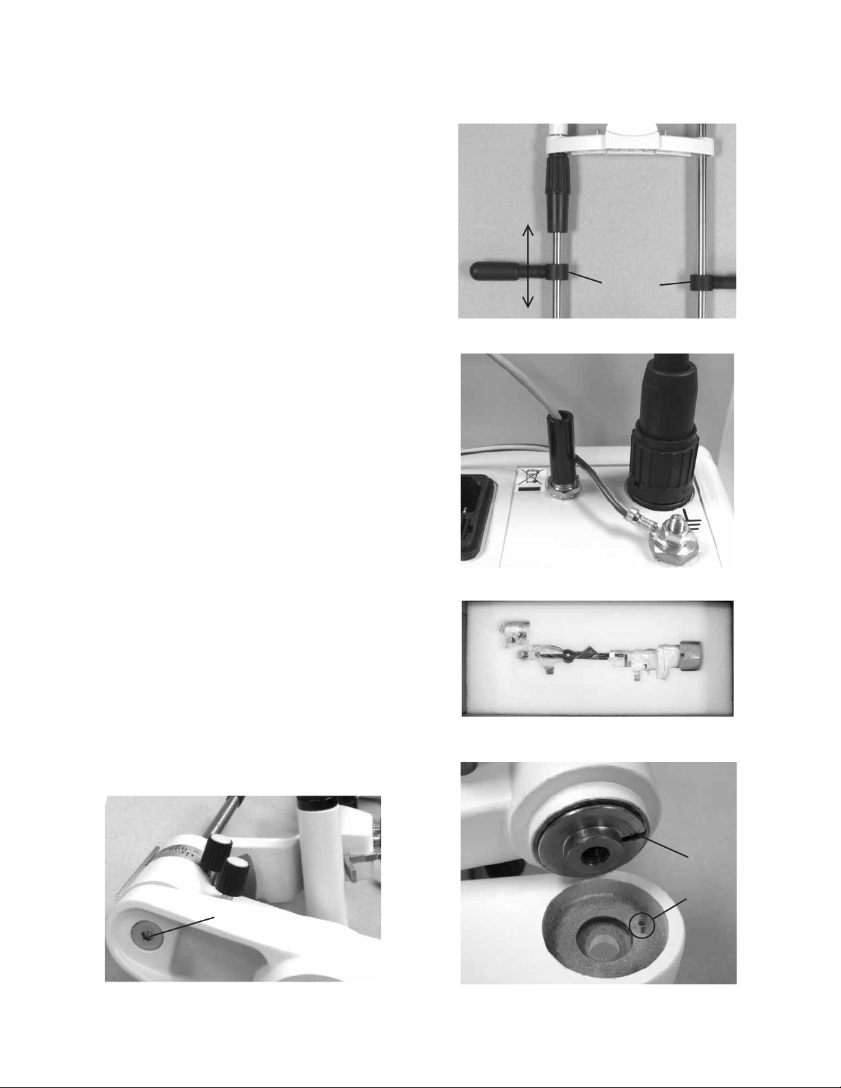
Setup ............................................................................................................ 9
Unpacking & Installation ............................................................................ 9
Application of Input Power....................................................................... 11
Disconnection of Input Power.................................................................. 11
Instructions for Use........................................................................................ 12
Operation................................................................................................. 12
Adjusting Slit Length ........................................................................... 13
Filters.................................................................................................. 13
Slit Rotation ........................................................................................ 14
Illumination Inclination ........................................................................ 14
Slit Centration ..................................................................................... 14
Cleaning & Maintenance ............................................................................... 15
Cleaning................................................................................................... 15
External Cleaning ............................................................................... 15
Forehead/Chinrest Cleaning & Disinfection........................................ 15
Cleaning the Glide Plate..................................................................... 15
Mirror Cleaning / Replacement........................................................... 15
Changing the Halogen Lamp................................................................... 16
Fuse Replacement................................................................................... 17
Troubleshooting ............................................................................................. 18
Chart of Common Errors.......................................................................... 18
Specications ................................................................................................ 19
Physical Dimensions................................................................................ 19
Electrical .................................................................................................. 19
Operational Conditions ............................................................................ 19
Optics....................................................................................................... 19
Movement Ranges................................................................................... 20
Compliance.............................................................................................. 20
Device Classication................................................................................ 20
Disposal................................................................................................... 20
Software Revision.................................................................................... 20
Guidance Tables............................................................................................ 21
Warranty ........................................................................................................ 25
Table of Contents

4 15140-101 Rev. C
Warnings & Cautions
Reichert Technologies®(Reichert) is not responsible for the safety and reliability of this instrument when:
• Assembly, disassembly, repair, or modication is made by unauthorized dealers or persons.
• Instrument is not used in accordance with this User’s Guide.
WARNING: AN INSTRUCTION THAT DRAWS ATTENTION TO RISK OF INJURY OR DEATH.
WARNING: UNITED STATES FEDERAL LAW AND EUROPEAN REGULATIONS REQUIRE THAT THIS
DEVICE BE PURCHASED ONLY BY A PHYSICIAN OR A PERSON ACTING ON BEHALF OF A PHYSICIAN.
WARNING: THIS INSTRUMENT SHOULD BE USED IN STRICT ACCORDANCE WITH THE
INSTRUCTIONS OUTLINED IN THIS USER’S GUIDE. THE SAFETY OF THE OPERATOR AND THE
PERFORMANCE OF THE INSTRUMENT CANNOT BE GUARANTEED IF USED IN A MANNER NOT
SPECIFIED BY REICHERT TECHNOLOGIES.
WARNING: DO NOT REPAIR OR SERVICE THIS INSTRUMENT WITHOUT AUTHORIZATION FROM
THE MANUFACTURER. ANY REPAIR OR SERVICE TO THIS INSTRUMENT MUST BE PERFORMED BY
EXPERIENCED PERSONNEL OR DEALERS WHO ARE TRAINED BY REICHERT OR SERIOUS INJURY
TO THE OPERATOR OR PATIENT MAY OCCUR.
WARNING: MODIFICATIONS TO THIS INSTRUMENT ARE NOT ALLOWED. ANY MODIFICATION TO
THIS UNIT MUST BE AUTHORIZED BY REICHERT OR SERIOUS INJURY TO THE OPERATOR OR
PATIENT MAY OCCUR.
WARNING: IF THIS INSTRUMENT IS MODIFIED, APPROPRIATE INSPECTION AND TESTING MUST BE
CONDUCTED TO ENSURE CONTINUED SAFE USE OF THIS INSTRUMENT.
WARNING: TO AVOID RISK OF ELECTRIC SHOCK, THIS EQUIPMENT MUST ONLY BE CONNECTED TO
A SUPPLY MAINS WITH PROTECTIVE EARTH OR DAMAGE TO THIS INSTRUMENT AND/OR INJURY TO
THE OPERATOR OR PATIENT MAY OCCUR.
WARNING: ENSURE THAT THE VOLTAGE APPLIED TO THE UNIT IS THE SAME AS THE VOLTAGE THAT
IS INDICATED ON THE DATA PLATE OR DAMAGE TO THE UNIT MAY OCCUR.
WARNING: THIS INSTRUMENT MUST BE PLUGGED INTO AN OUTLET WITH AN EARTH GROUND. DO
NOT REMOVE OR DEFEAT THE EARTH GROUND CONNECTION ON POWER INPUT CONNECTOR
OR THE UNIT’S POWER CORD OF THIS INSTRUMENT OR DAMAGE TO IT AND/OR INJURY TO THE
OPERATOR OR PATIENT MAY OCCUR.
WARNING: THE EQUIPMENT OR SYSTEM SHOULD NOT BE USED ADJACENT TO OR STACKED WITH
OTHER EQUIPMENT AND THAT IF ADJACENT OR STACKED USE IS NECESSARY, THE EQUIPMENT
OR SYSTEM SHOULD BE OBSERVED TO VERIFY NORMAL OPERATION IN THE CONFIGURATION IN
WHICH IT WILL BE USED.
WARNING: THIS INSTRUMENT IS NOT SUITABLE FOR USE IN THE PRESENCE OF FLAMMABLE
ANESTHETIC MIXTURES, SUCH AS OXYGEN OR NITROUS OXIDE.
WARNING: BECAUSE PROLONGED INTENSE LIGHT EXPOSURE CAN DAMAGE THE RETINA, THE
USE OF THE DEVICE FOR OCULAR EXAMINATION SHOULD NOT BE UNNECESSARILY PROLONGED,
AND THE BRIGHTNESS SETTING SHOULD NOT EXCEED WHAT IS NEEDED TO PROVIDE CLEAR
VISUALIZATION OF THE TARGET STRUCTURES. THIS DEVICE SHOULD BE USED WITH THE
INTEGRATED FILTERS WHICH PROTECT AGAINST UV RADIATION.
WARNING: THE USE OF ACCESSORIES OR CABLES OTHER THAN THOSE SPECIFIED, WITH THE
EXCEPTION OF THOSE SOLD BY THE MANUFACTURER AS REPLACEMENT PARTS FOR THE
INTERNAL COMPONENTS, MAY RESULT IN INCREASED EMISSIONS OR DECREASED IMMUNITY OF
THE EQUIPMENT OR SYSTEM.

5
15140-101 Rev. C
CAUTION: AN INSTRUCTION THAT DRAWS ATTENTION TO THE RISK OF DAMAGE TO THE PRODUCT.
CAUTION: THE INTERNAL CIRCUITRY OF THE INSTRUMENT CONTAINS ELECTROSTATIC DISCHARGE
SENSITIVE DEVICES (ESD) THAT MAY BE SENSITIVE TO STATIC CHARGES PRODUCED BY THE HUMAN
BODY. DO NOT REMOVE THE COVERS WITHOUT TAKING PROPER ESD PRECAUTIONS.
CAUTION: DO NOT USE SOLVENTS OR STRONG CLEANING SOLUTIONS ON ANY PART OF THIS
INSTRUMENT AS DAMAGE TO THE UNIT MAY OCCUR. SEE MAINTENANCE SECTION FOR DETAILED
CLEANING INSTRUCTION.
CAUTION: MEDICAL ELECTRONIC EQUIPMENT NEEDS SPECIAL PRECAUTIONS REGARDING EMC AND
NEEDS TO BE INSTALLED AND PUT INTO SERVICE ACCORDING TO THE EMC INFORMATION PROVIDED
IN THE ACCOMPANYING DOCUMENTS.
CAUTION: PORTABLE AND MOBILE RF COMMUNICATIONS EQUIPMENT CAN AFFECT MEDICAL
ELECTRICAL EQUIPMENT.
CAUTION: THIS INSTRUMENT IS NOT TO BE USED NEAR HIGH-FREQUENCY EMITTING SURGICAL
EQUIPMENT.
CAUTION: THIS INSTRUMENT IS NOT INTENDED TO BE CONNECTED TO EQUIPMENT OUTSIDE THE
CONTROL OF REICHERT TECHNOLOGIES OR MUST BE TESTED TO AN APPLICABLE IEC OR ISO
STANDARDS.
CAUTION: THE LIGHT EMITTED FROM THIS INSTRUMENT IS POTENTIALLY HAZARDOUS. THE LONGER
THE DURATION OF EXPOSURE, THE GREATER THE RISK OF OCULAR DAMAGE. EXPOSURE TO LIGHT
FROM THIS INSTRUMENT WHEN OPERATED AT MAXIMUM INTENSITY WILL EXCEED THE SAFETY
GUIDELINE AFTER 9.5 MINUTES.
Warnings & Cautions (continued)

6 15140-101 Rev. C
Symbol Information
Symbol Information
The following symbols appear on the instrument:
Caution symbol indicating important operating and maintenance
instructions that are included in this User’s Guide
Type B Applied Part
Accompanying Documents must be consulted
Alternating Current Power
Protective Earth Connection
ON / OFF
2014
Date of Manufacture
REF Catalog Number
S/N Serial Number
Waste of Electrical and Electronic Equipment
Compliance to Medical Device Directive 93/42/EEC
36FS
Underwriter's Laboratories has independently evaluated this device
using selected tests from US and Canadian versions of IEC 60601-1
standard, and assigned a control number
Authorized Representative in European Community
Fragile Contents in Shipping Container - handle with care
Keep Dry - Package shall be kept away from rain
This Way Up - Indicates correct upright position of package

7
15140-101 Rev. C
Introduction
Congratulations on the purchase of your new Xcel®455 Slit Lamp from Reichert Technologies®.
This user’s guide is designed as a training and reference manual for the operation and maintenance
of the instrument. We recommend that you read it carefully prior to use and follow the instructions to
ensure optimum performance of your new instrument. Properly trained eyecare professionals such as
ophthalmologists, optometrists, opticians and eye care technicians should operate this instrument.
Please retain this manual for future reference and to share with other users. Additional copies can be
obtained from your authorized Reichert®distributor or from the Reichert customer service department at:
Tel: 716-686-4500
Fax: 716-686-4555
Email: [email protected]
Indications for use
The Xcel 455 Slit Lamp is an AC-powered slit lamp biomicroscope that is intended for use in examining the
anterior eye segment, from the corneal epithelium to the posterior capsule. It is used to aid in the diagnosis
of diseases or trauma, which affect the structural properties of the anterior segment of the eye.
Contraindications
None.
Phototoxicity Information
Because prolonged intense light exposure can damage the retina, the use of the device for ocular examination
should not be unnecessarily prolonged, and the brightness setting should not exceed what is needed to
provide clear visualization of the target structures. This device should be used with filters that eliminate UV
radiation (< 400 nm) and, whenever possible, filters that eliminate short-wavelength blue light (< 420 nm).
The retinal exposure dose for a photochemical hazard is a product of the radiance and the exposure time. If
the value of radiance were reduced in half, twice the time would be needed to reach the maximum exposure
limit.
While no acute optical radiation hazards have been identified for slit lamps, it is recommended that the intensity
of light directed into the patient’s eye be limited to the minimum level which is necessary for diagnosis. Infants,
aphakes and persons with diseased eyes will be at greater risk. The risk may also be increased if the person
being examined has had any exposure with the same instrument or any other ophthalmic instrument using a
visible light source during the previous 24 hours. This will apply particularly if the eye has been exposed to
retinal photography.

8 15140-101 Rev. C
1
2
18
3
4
5
6
8
10
11
12
13
14
15
16
17
20
21
9
19
7
Features and Functions
Parts Identication
1. On/Off Switch
2. Illumination Level Control
3. Glide Plate
4. Joystick for horizontal and vertical adjustment
5. Microscope Arm Lock-Knob
6. Slit Width Knob
7. Inclination Latch Release
8. Centering Knob
9. Breath Shield Mount
10. Eyepieces
11. Focusing Rings
12. Magnification Dial
13. Lamp Housing Cover
14. Fixation Light
15. Filter Lever
16. Slit Rotation/Length Knob
17. Slit Rotation Scale
18. Microscope Lock Knob
19. Illumination Arm Lock Knob
20. Instrument Base Lock Knob
21. Guide Rail Covers
Xcel 455 Package Contents
• Xcel 455 Slit Lamp (15140)
• User's Guide (15140-101)
Accessories
• Focusing Rod (P/N 15120-226)
• Hex Wrench (3mm) (P/N X54264)
• Hex Wrench (4mm) (P/N X54248)
• Hex Wrench (5mm) (P/N X54398)
• Dust Cover (P/N 15140-004)
• Halogen Lamp, Main (P/N 15121)
• Guide Rail Covers (P/N 15120-031)
• Replacement Fuses (P/N RFAG20063)
• Chin Rest Paper - 1 pack (P/N 15120-051)
• Power Cord (P/N 15120-036)

9
15140-101 Rev. C
Setup
Unpacking and Installation
1. Open the outside shipping box and remove the
four (4) inner boxes.
2. Remove the User's Guide and read it.
3. Open the box with the Table Top and Electronics
in it. Refer to Figure SU-1.
4. Remove the Table Top from the box and install
the Table Top onto the instrument stand and
secure it into place as indicated in the user guide
for the stand.
5. Open the box with the Chin Rest Assembly and
remove it. Refer to Figure SU-2.
6. Open the box with the Microscope Assembly.
Remove the Microscope Assembly, Base
Assembly, and Accessories. Refer to Figure SU-3.
7. Remove the accessories and store them in an
appropriate place so that when they are needed
they will be available. Refer to Figure SU-4.
8. Using the 3mm Hex Wrench, connect the
Ground Wire from the Power Supply to the Chin
Rest Assembly using the Ground Screw provided
(torque to 7.8 N•m). Refer to Figure SU-5.
9. Using the 5mm Hex Wrench, remove the two
Screws from the bottom of the Table Top and
attach the Chin Rest Assembly to the Table Top
using these Screws. Refer to Figure SU-6.
Figure SU-3 Microscope, Base, Accessories
Base
Microscope
Accessories
Figure SU-5 Chin Rest Ground
Ground
Screw
Ground Wire
Figure SU-1 Table Top and Electronics
Figure SU-2 Chin Rest Assembly
Figure SU-4 Accessories
Wrenches
Power
Cord
Guide Rails Replacement
Lamp
Chin Paper
Dust
Cover
Focusing
Rod
Figure SU-6 Table Top Screws
Screws

10 15140-101 Rev. C
Setup (continued)
Unpacking and Installation (continued)
10. Using the 4mm Hex Wrench, adjust the Patient
Handles by loosening the Screws that are
securing them to the Chinrest Posts. Slide
the Patient Handles up or down to the desired
height, and secure them in place by tightening
the Allen Cap Screws. Refer to Figure SU-7.
11. Attach the Fixation Light Wire from the Chin Rest
Assembly into the connector on the back of the
Power Supply Assembly. Refer to Figure SU-8.
12. Open the box with the Illumination Assembly and
remove it. Refer to Figure SU-9.
13. Using the 5mm Hex Wrench, remove the Screw on
the bottom of the Illumination Assembly and Arm.
Note: The Illumination Assembly and Arm are con-
nected as one piece.
14. Mount the Illumination Assembly and Arm onto the
Base Assembly and secure it with the Screw using
the 5mm Hex Wrench. Refer to Figure SU-10.
Note: There is a Notch in the Base Assembly, and
a Slot in the Illumination Assembly. Align the
Illumination Assembly and Arm so the Notch
goes into the Slot. If the Notch is not aligned
properly, the Slit Lamp will not sit ush, and
won’t be aligned properly. Refer to Figure
SU-11.
-continued-
Figure SU-10 Screw
Screw
Base
Assembly
Arm Illumination
Assembly
Figure SU-7 Adjusting Patient Handle Height
Screws
Move
Handles Up
or Down
Figure SU-8 Connections
Fixation
Light Wire
Base
Lamp
Wire
Figure SU-9 Illumination Assembly
Figure SU-11 Line Up Notch
Illumination
Assembly
and
Arm
Base
Slot
Notch

11
15140-101 Rev. C
Setup (continued)
Unpacking and Installation (continued)
15. Install the Base Assembly onto the tracks of
the Table Top and slide the Guide Rail Covers
around the tracks. Refer to Figure SU-12.
16. Attach the Base Lamp Wire to the back of the
Power Supply Assembly. Refer to Figure SU-8.
17. Install the Microscope Assembly onto the top of
the Arm by sliding it into position, making sure
it is up against the stop. Then, tighten the Lock
Knob located on the right side of the Microscope
Assembly. Refer to Figure SU-13.
Note: Do not adjust the microscope stop knob
behind the base of the microscope or the
vertex distance will cause misalignment of
focus and require re-calibration of the slit
lamp assembly.
Application of Input Power
WARNING: CARE MUST BE TAKEN TO ARRANGE THE
CABLES FOR THE ACCESSORIES SUCH THAT THEY DO
NOT PRESENT A TRIPPING HAZARD TO THE EXAMINER
OR A DANGER TO THE PATIENT.
WARNING: POSITION THIS INSTRUMENT SO THAT IT
IS NOT DIFFICULT TO OPERATE THE DISCONNECTION
DEVICE (PLUG).
1. After the unit is in its secure location, apply the
correct input voltage to the instrument using the
Power Cord.
Note: The power inlet is located on the backside of
the Power Supply Assembly.
2. Activate ON/OFF Switch (I). Refer to Figure SU-14.
Note: The ON/OFF Switch will illuminate green when
there is power to the unit. When the ON/OFF
Switch is set to off, the green light will turn off.
Disconnection of Input Power
1. At any time, the power switch can be set to OFF.
The unit does not have a power down sequence.
To terminate operation of this instrument, press
the ON / OFF switch to the OFF position (O).
2. If this instrument is intended to be OFF for an
extended period of time, it can be disconnected
from power by detaching the power cord from
the receptacle.
Figure SU-12 Install Base Assembly
Slide
Figure SU-13 Microscope Install
Turn Clockwise
Lock Knob
Microscope
Assembly
Slide
Figure SU-14 Power Supply Assembly
ON/OFF Switch
Illumination Level Control Knob

12 15140-101 Rev. C
Instructions for Use
Operation
1. Turn on the power using the On/Off switch located
on the front of the Power Supply Assembly.
Brightness can be adjusted by rotating the
Illumination Level Control Knob.
Refer to Figure SU-14.
Note: The maximum intensity setting is for
intermittent use only. Continuous use will
shorten the lamp life.
2. Insert the Focusing Rod in the pivot post of the
instrument body to make rough PD and focus
adjustments. Refer to Figure IN-1.
3. Position the light onto the flat surface of the
Focusing Rod and adjust the pupillary distance
and focus of the eyepieces to suit the needs of the
operator.
4. Using the Slit Width Knobs, adjust the projected
slit so that the thinnest slit is shown on the
Focusing Rod. Refer to Figure IN-2.
Note: The thinnest slit will allow for greater accuracy.
5. Remove the Focusing Rod.
6. To position a patient, adjust the chinrest height
by turning the Chinrest Elevation Handle on the
post of the Chin Rest Assembly until the patient’s
canthus is in line with the Canthus Mark on the
chin rest post. Refer to Figures IN-2 and IN-3.
7. Microscope elevation is adjusted by rotating the
joystick and observing the slit image through the
Microscope Assembly until the slit is centered on
the patient's cornea. Refer to Figure IN-4.
8. Move the slit lamp with the joystick held firmly
and slightly angled toward the patient, until the slit
appears sharply on the cornea.
Note: The accuracy of this rough adjustment should
be checked by the naked eye. The ne
adjustment is performed while observing the
slit through the microscope.
9. Tilt the joystick, which is now held lightly at its
upper end, until the slit appears sharply at the
depth of the eye which is to be observed.
10. The horizontal motion of the base can be locked
by tightening the base locking screw. Refer to
Figure IN-4.
Note: Lock the base whenever the lamp is not in use.
Figure IN-1 Install Focusing Rod
Focusing
Rod
Figure IN-2 Slit Width and Patient Height
Chinrest
Elevation
Handle
Slit
Width
Knobs
Figure IN-3 Adjust Patient Height
Canthus
Mark
Figure IN-4 Adjust Height
Adjust Lamp
Height Lock
Base

13
15140-101 Rev. C
Operation (continued)
11. The angle between the illumination system and
the microscope can be varied between 0° and
90° to either the left or right. Refer to Figure IN-5.
12. The illumination angle is indicated on the
Illumination Angle Scale on the slit lamp arm.
Refer to Figure IN-6.
13. Magnification is altered by rotating the
Magnification Dial on the Microscope Assembly.
Refer to Figure IN-5.
Note: The magnication of each click-stop position
is engraved on the Magnication Dial.
14. The slit width can be adjusted by rotating the Slit
Width Knobs. Refer to Figure IN-7.
Adjusting Slit Length
The slit length is adjusted by rotating the Slit Length/
Rotation Dial. The dial has five stops for adjustments.
They are 12, 9, 5, 3, 1 and 0.3 mm diameter and
continuous length. Refer to Figure IN-8.
Filters
There are five filters that can be used by indexing
the Filter Lever to the coordinating Filter Dot. The
Filter Dots are color coded. Refer to Figure IN-8.
The color coded filters are as follows:
Blue dot = Cobalt Blue
Red dot = Heat Absorbing
White dot = Open
Gray dot = Neutral Density
Green dot = Red-free
Figure IN-7 Slit Width Adjustment
Slit
Width
Knobs
Figure IN-5 Illumination Angle
Magnification
Dial
Illumination
Angle
Figure IN-6 Illumination Angle Scale
Figure IN-8 Slit Width and Filters
Slit
Length/Rotation
Dial
Slit
Length Scale
Filter
Lever
Filter Dots
(Only 3 Visible
in Figure
Instructions for Use (continued)

14 15140-101 Rev. C
Operation (continued)
Slit Rotation
By grasping the Slit Rotation/Length Knob, the lamp
housing can be rotated. This, in turn, rotates the slit
from vertical to horizontal in either direction. The slit
positions are click-stopped in 45° increments and
stopped at 0° and 180° and is indicated by the scale.
Refer to Figure IN-9.
Illumination Inclination
The Illumination Assembly can be inclined in the
horizontal plane in 5° steps for a total of 20°. Tilt the
Illumination Assembly by depressing the Inclination
Latch Release and pulling the base of the Illumination
Assembly toward the operator. Refer to Figure IN-10.
Slit Centration
When the centering screw is loosened, the slit can
be scanned away from the center of the field of
vision for retro-illumination, scleral scatter, etc. The
slit image is centered again by tightening the screw.
Refer to Figure IN-11.
Figure IN-9 Slit Rotation Scale
Slit
Rotation
Scale
Slit Rotation/
Length Knob
Figure IN-10 Illumination Inclination
Inclination
Latch
Release
Pull
Illumination
Assembly
Forward
Slit
Centering
Knob
Figure IN-11 Slit Centering
Centering
Knob
Instructions for Use (continued)

15
15140-101 Rev. C
Cleaning & Maintenance
WARNING: RISK OF ELECTRIC SHOCK. ALWAYS
DISCONNECT THE POWER CORD FROM THE WALL AND
THE INSTRUMENT BEFORE PERFORMING ANY OF THE
FOLLOWING CARE AND MAINTENANCE PROCEDURES.
Cleaning
External Cleaning
Clean the external surfaces of this instrument using
a clean, soft cloth moistened with a mild detergent
solution (1 cc of liquid dish soap to one liter of clean,
filtered water). Refer to Figure MM-1.
Forehead / Chinrest Cleaning & Disinfection
For hygienic reasons, wipe the forehead rest with an
alcohol wipe and change the chin rest papers after
each patient.
Cleaning the Glide Plate
If the Glide Plate is dirty it may cause a rough feeling
when maneuvering the base of the slit lamp. Clean
the Glide Plate with a soft cloth lightly dampened
with a mild detergent solution (1 cc of liquid dish soap
to one liter of clean, filtered water).
Mirror Cleaning / Replacement
When cleaning the mirror, clean off the mirror using
dry air, then gently wipe with a soft lint-free cloth. If
replacing the mirror, grasp the narrow shank of the
mirror and pull upwards. Replace it with a new one
by sliding it in place. Refer to Figure MM-2.
Figure MM-1 Cleaning Main Unit
Figure MM-2 Remove Mirror
Pull
Out
Mirror

16 15140-101 Rev. C
Changing The Halogen Lamp
WARNING: NEVER REMOVE A LAMP THAT HAS
RECENTLY BEEN IN USE AS IT WILL BE VERY HOT. WAIT
UNTIL IT HAS COOLED AND USE GLOVES OR A THICK
CLOTH WHEN HANDLING ANY HALOGEN LAMP.
WARNING: REPLACE HALOGEN LAMP ONLY WITH
REICHERT P/N 15121 TO ENSURE PATIENT LIGHT LEVEL
SAFETY.
WARNING: NEVER TOUCH A HALOGEN LAMP WITH
BARE HANDS AS FINGERPRINTS WILL SHORTEN THE
LAMP LIFE.
1. Remove input power to the instrument.
2. Remove the Lamp Housing Cover by loosening
the Two Screws securing the Cover and lifting it
straight off. Refer to Figure MM-3.
3. Using a Philips head screwdriver, unscrew the
Screw securing the Metal Tab holding the Lamp
Holder in place. Refer to Figure MM-4.
4. Gently pull out the Lamp Holder and Lamp.
Refer to Figure MM-5.
5. Grip the Lamp by the Metal Disk that is attached
to it, and pull it out of the Lamp Holder.
Refer to Figure MM-6.
6. Replace the Lamp with a new one and install it
by pushing the prongs into the Lamp Holder so
that the Notch is positioned to the right. Refer to
Figures MM-6 and MM-7.
Note: There is a Cut Out in the Metal Disk on
the Lamp. Ensure that the Lamp is placed
properly so that the Cut Out ts into the
Notch. Refer to Figure MM-7.
7. Secure the Lamp with the Metal Tab and Screw.
Refer to Figure MM-4.
8. Install the Lamp Housing Cover and secure it by
tightening the Two Screws. Refer to Figure MM-3.
Figure MM-3 Remove Cover
Two Screws
Lamp Housing
Cover
Pull Up
Figure MM-4 Securing Screw
Screw
Lamp
Holder
Metal
Tab
Figure MM-5 Lamp
Lamp
Lamp
Holder
Figure MM-6 New Lamp
Lamp
Lamp
Holder Metal
Disk
Figure MM-7 Notch
Notch
Cut Out
Lamp
Holder
Metal
Disk
Cleaning & Maintenance (continued)

17
15140-101 Rev. C
Fuse Replacement
Replace the fuses in the Power Input Module with
the fuses indicated in the Specifications section of
this manual.
1. Remove input power to the instrument.
2. Press down on the top tab in the middle of the
Power Input Module to release the Fuse Holder,
and gently pull out the Fuse Holder by gripping the
two small tabs. Refer to Figures MM-8 and MM-9.
3. Open the Door to the Fuse Holder by pulling it
down. Refer to Figure MM-9.
Note: The Fuses will pop up when the door is
open, making removal easier.
4. Install new fuses into the Fuse Holder that is
indicated in the Specication section of this
manual.
5. Install the Fuse Holder by closing the door, and
pushing the Fuse Holder back until it snaps into
place.
Figure MM-8 Pull Out
Pull
Out
Tabs
Figure MM-9 Open Fuse Door
Open
Door
Fuses
Cleaning & Maintenance (continued)

18 15140-101 Rev. C
Troubleshooting
The following chart outlines some common issues with the Xcel 455 Slit Lamp and some steps you can take
to correct the issue. If problems persist, please contact the Reichert as listed in the Introduction section of
this manual.
Chart of Common Errors
ISSUE PROBABLE CAUSE POSSIBLE SOLUTION
Lamp won’t turn on.
Incorrect input power supplied to
the Xcel 455 Slit Lamp.
Check the outlet to ensure proper power in
being supplied.
Defective Power Cord. Replace the Power Cord.
Lamp may be blown out. Replace the Lamp.
Defective Power Supply. Replace the Power Supply Assembly.
Slit Lamp won’t move.
Rubber stopper may be attached
under the joystick. Remove the rubber stopper.
Base Lock Screw may be tightened. Loosen the Base Lock Screw.
Rough base
movement.
Rubber stopper may be attached
under the joystick. Remove the rubber stopper.
Bearings may be damaged. Replace the base.
Shaft may be damaged. Replace the base.
Fixation light does not
light up.
Fixation Light Harness not plugged
into the Power Supply Assembly.
Ensure the Fixation Light Harness is properly
seated in the Power Supply Assembly.
Defective Power Supply. Replace the Power Supply Assembly.
Light too dim.
Incorrect wattage for lamp being
used. Replace with the proper lamp.
Lamp not installed properly. Check lamp and ensure notch lines up with
lamp housing.
Double slit visible in
microscope.
Microscope not focused on focusing
rod before use.
Install focusing rod and check to ensure
microscope is focused on it.
Lamp not installed properly. Check lamp and ensure notch lines up with
lamp housing.
The following is a checklist of items that need to be assessed in order to determine if the Xcel 455 Slit Lamp
requires servicing.
• Check the outside of the slit lamp for any damage or missing components.
• Inspect the power cord for damage.
• Test the lamp by turning the lamp on and turning the light all the way to it’s brightest setting, and all
the way down to it’s lowest setting.
• Check to ensure all switches are functioning properly.
• Check the Filters by cycling through all the options.
• Check the Slit Wheel by cycling through all the options.
• Check the base movement.

19
15140-101 Rev. C
Specications
Catalog Number 15140
Physical Dimensions
Size (From Tabletop): Weight, unpacked: 39.3 lbs (17.8 Kg)
Height: 26.0 in. (66.0 cm) Weight, packed: 65 lbs (29.5 Kg)
Width: 18.0 in. (45.7 cm)
Depth: 13.5 in. (34.3 cm)
Electrical
Voltage: 100V-240 VAC
Power Input (max): 56-73 VA
Frequency: 50/60 Hz
Fuses: Time-Lag (1.6A, 250V), 5x20 mm, (P/N RFAG20063)
Halogen Lamp: P/N 15121 (6V, 20 W)
Operational Conditions
Environmental:
The environmental conditions are as follows:
Operating:
Temperature 10° C (50° F) to 35° C (95° F)
Relative Humidity: 30% to 75%
Atmospheric Pressure: 80 kPa (23.6 in. Hg) to
106 kPa (31.3 in. Hg)
Transportation & Storage:
Temperature -20° C (-4° F) to 70° C (158° F)
Relative Humidity: 10% to 80%
Atmospheric Pressure: 50 kPa (14.8 in. Hg) to
106 kPa (31.3 in. Hg)
Optics
Microscope Galilean
Mag Change 5 Step Drum Rotation
Eyepiece 12.5X
Mag Ratio 6.5X, 10X, 16X, 25X, 40X
PD Range 49 - 78 mm
Diopter Adjustment +/- 6 D
Slit Illumination 6V 20W Halogen
Slit Width 0 - 12 mm
Slit Length 1.5 - 12.5 mm
Slit Apertures 0.3, 1, 3, 5, 9, 12 mm
Slit Rotation 0° - 180°
Slit Inclines -5°, -10°, -15°, -20°
Filters Red Free, Heat Absorbing, Cobalt Blue, Neutral Density
Working Distance < 370 mm
Illuminance Range 0 to > 50000 lux
-20°C
70°C
10%
80%
106 kPa
50 kPa

20 15140-101 Rev. C
Field of View
Magnification Field of View (mm)
6.5 X 37.0
10 X 24.0
16X 15.0
25X 9.5
40X 6.0
Movement Ranges
Longitudinal (In/Out) 4.3 in. (110 mm )
Lateral (Left/Right) 4.3 in. (110 mm )
Vertical (Up/Down) 1.2 in. (30 mm )
Chinrest Range 2.8 in. (70 mm )
Table Dimensions 18.3 in. x 12.6 in. (465 mm x 320 mm)
Compliance
This slit lamp complies with:
IEC 60601-1
ISO 10939
ISO 15004-1
ISO 15004-2
Device Classification
Protection: Class I
Ingress Protection Rating: IXP0
Instrument Type: (IEC 60601-1) B
Operating Mode: Continuous
US FDA: Class II 21 CFR 886.1850
EU Medical Device Directive: Class I, Rule 12
CAN CMDR: Class I Rule 7, Clause 1
Disposal
This product does not generate any environmentally hazardous residues. At the end of its product life, follow
your local laws and ordinances regarding the proper disposal of this equipment.
Software Revision
There is no software installed in this unit.
Due to a policy of continuous development, we reserve the right to change specications without notice.
Specications (continued)
Table of contents
Other Reichert Laboratory Equipment manuals
Popular Laboratory Equipment manuals by other brands

Oxford Instruments
Oxford Instruments Andor Marana-X-11 quick start guide

WEPA
WEPA TOPITEC TOUCH user manual

Buchi
Buchi Encapsulator B-390 Operation manual

Oxford
Oxford OptistatDN USER MANUAL - ORIGINAL INSTRUCTIONS

Cole Parmer
Cole Parmer HG-400 MiniG Operation manual

Atlas
Atlas SUNTEST CPS operating manual