Reliable DDX Maintenance manual

Reliable Automatic Sprinkler Co., Inc., 103 Fairview Park Drive, Elmsford, New York 10523
Model DDX
Single Interlock Preaction Systems
2” (50 mm), 2½” (65 mm), 3” (80 mm),
76 mm, 4” (100 mm), 6” (150 mm),
165 mm & 8” (200 mm)
Bulletin 749 January 2021
Instructions for Installation,
Operation, Care, and
Maintenance
Wet Pilot Line,
Dry Pilot Line, and
Electric Actuation Trims
•Electric Release Trim Available with 175 psi (12.1
bar) or 300 psi (20.7 bar) Rated Solenoid Valve
•Electric Release Trim and Wet Pilot Trim Utilizing 7
to 10 psi (0.5 to 0.7 bar) Pneumatic Supervising
Pressure
•Dry Pilot Trim Utilizing 8 psi to 28 psi (0.6 to 1.9
bar) Pneumatic Supervising Pressure
•Externally Resettable Clapper
•One Main Drain
Model DDX Single Interlock Preaction
(Shown with Electric Actuation Trim)

2.
General
Single Interlock Preaction Systems are designed for water
sensitive areas that require protection from inadvertent water
flow into the sprinkler system piping.
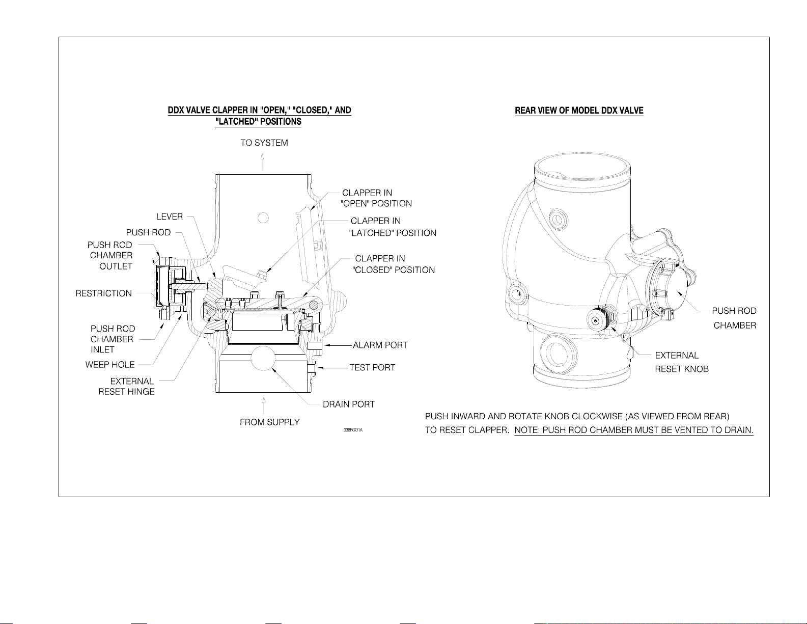
At the heart of the Reliable Single Interlock Preaction System
is the Model DDX Deluge Valve. This deluge valve is a hydrau-
lically operated, straight-through-design, differential latching
clapper-type (see Fig. 1). System maintenance is simplied
since the deluge valve can be reset externally without removing
the cover plate. This feature provides a signicant system-res-
toration time advantage. The Model DDX Deluge Valve has an
intermediate chamber and thereby does not require an in-line
air check valve. Subsequently, the deluge valve only requires a
single drain connection.
The trim sets for the single interlock preaction systems provide
all of the necessary equipment for connections to the Model
DDX Deluge Valve’s pushrod chamber inlet and outlet ports, a
1¼” (30 mm) main drain on 2” (50 mm), 2½” (65 mm), 76 mm
and 3” (80 mm) valve sizes or a 2” (50 mm) main drain on 4”
(100 mm), 165 mm, 6” (150 mm) and 8” (200 mm) valve sizes,
alarm devices, air supply, and required pressure gauges. The
trim sets are available in individual (loose) parts, in time-saving,
segmented assembled kit forms or fully assembled to the Model
DDX Deluge Valve (with or without a control valve). The major
benets of a single interlock preaction system, when compared
with a wet pipe or deluge system are as follows:
• A re alarm sounds prior to the operation of a sprinkler
head, which may enable extinguishing the re by handheld
means before the actual operation of any sprinklers and
subsequent water damage.
• A trouble annunciator signals whenever the integrity of
the piping or sprinklers is accidentally or intentionally dis-
turbed; however, no water flow or water damage will occur
at that time.
• Speedy detection and an early re alarm are provided by
re detectors, without the delay associated with water de-
livery time in the event of a re. Note that with a wet pipe
system, the re alarm is delayed until after water has begun
flowing from an operated sprinkler head.
Sprinkler piping in Wet Pilot and Electric Actuation Single
Interlock Preaction Systems can effectively be supervised by
means of a Reliable Model B-SI Air Compressor Panel or Model
C-SI Air Compressor Panel. Loss of supervisory pneumatic
pressure due to a damaged sprinkler or sprinkler pipe will not
cause water to flow through the Model DDX Deluge Valve and
into the system piping. Loss of pneumatic pressure will activate
a trouble-annunciating device when the system pressure falls
below approximately 4 psi (0.3 bar). Note: Wherever the word
“air” is used in this bulletin as a reference to the pneumatic pres-
sure source it shall also mean “air or nitrogen.”
Wet Pilot Line Single Interlock Preaction Systems use a
pilot line consisting of a line of closed sprinklers or pilot line de-
tectors (Reliable’s Model F1-FTR), which are located in the area
to be protected. These sprinklers/detectors are more sensitive
(lower activation temperature) than the sprinkler heads installed
in the re sprinkler system. The wet pilot line is directly installed
to the Model DDX Deluge Valve pushrod chamber. Wet pilot
line sprinklers are detection devices and do not provide any wa-
ter to aid in the reghting capability of the re sprinkler system.
To fully operate a Wet Pilot Line Single Interlock Preaction
System, heat from a re must fuse a wet pilot line sprinkler/
detector thereby releasing the water pressure from the Deluge
Valve pushrod chamber. As water pressure is lost in this cham-
ber, the main water supply will open the Deluge Valve clapper,
thereby flowing water into the re sprinkler piping. Water flowing
into the system will flow through the intermediate chamber of
the deluge valve to a mechanical sprinkler alarm (if present) will
simultaneously activate the alarm pressure switch mounted in
the trim. The alarm pressure switch can electrically initiate the
shut-down or start up of equipment, such as computer, HVAC,
or other secondary alarm devices. The flow of water into the
sprinkler system piping converts the dry system into a wet sys-
tem. In the event that the re subsequently produces enough
heat to operate a re sprinkler, water will flow from that sprinkler.
The re sprinkler system piping supervised (see NFPA 13)
with air pressure. Loss of supervisory air due to a damaged
sprinkler or the sprinkler piping will not cause the Model DDX
Deluge Valve to open. The supervisory air supply for the re
sprinkler piping may effectively be supervised by the Reliable
Model B-SI Air Compressor Panel or the Reliable Model C-SI
Air Compressor Panel. Other options include the use of the Re-
liable NS-PaK or Nitrogen Regulator with an approved nitrogen
source, the Reliable Model A Pressure Maintenance Device
with a tank-mounted air compressor, or a tank-less air com-
pressor controlled by a pressure switch or the Reliable Model B
Air Maintenance Device. (See Reliable Bulletin 251).
In Electric Actuation Single Interlock Preaction Sys-
tems, when one electrical detector senses the presence of
re, the electrical releasing control panel operates the normally-
closed solenoid valve (175 psi (12.1 bar) or 300 psi (20.7 bar)
rated) to the open position. The solenoid valve, when closed,
retains sufcient water pressure in the pushrod chamber of the
Model DDX Deluge Valve to maintain it closed. Energizing the
solenoid valve relieves the water pressure, thus opening the
Deluge Valve and allowing water to flow into the sprinkler sys-
tem. The flow of water into the sprinkler system piping con-
verts the dry system into a wet system. In the event that the re
subsequently produces enough heat to operate a re sprinkler,
water will flow from that sprinkler.
To fully operate a cross-zoned single interlock system, two
electrical detectors must activate and a sprinkler must open.
During the early stages of a re, smoke or heat activates the
rst detector, which causes the control panel to produce a local
alarm and an alarm at the main re alarm panel. Electrical relays
inside the releasing control panel can be used to shut down air
moving equipment or activate security doors and other electri-
cal devices when the panel goes into the rst alarm condition.
Subsequent activation of a second, nearby or adjacent, detec-
tor will cause the panel to energize the solenoid valve open and
release water into the sprinkler system piping. Water flowing
into the sprinkler system piping will simultaneously activate the
alarm pressure switch on the valve trim. This pressure switch
can electrically initiate the shut down or startup of equipment,
such as computers or other second alarm devices. The flow of
water into the sprinkler system piping effectively converts the
dry system into a wet pipe system. In the event that the re sub-
sequently produces sufcient heat to operate a sprinkler.

Dry Pilot Single Interlock Preaction Systems are used in
areas that may be subjected to freezing conditions. They can
also be utilized to obtain installed sprinkler heights and pipe
lengths greater than the allowed for wet pilot systems. A dry
pilot line installation consists of an air-pressurized line of closed
sprinklers or pilot line detectors (Reliable Model F1-FTR), which
are located in the area to be protected. NFPA 72 or the Author-
ity Having Jurisdiction (AHJ) should be consulted for spacing
and elevation requirements for the installation of dry pilot sprin-
klers/detectors.
To maintain the Model DDX Deluge Valve in a closed posi-
tion: in areas where moisture-laden air could cause a freezing
condition, or other problems in the dry pilot line, the use of a dry,
compressed gas such as nitrogen is suggested. Approved gas
handling regulators (see Reliable Bulletin 254) and connections
are recommended.
The re sprinkler system piping is generally supervised (see
NFPA 13) with air pressure. Loss of supervisory air due to a
damaged sprinkler or the sprinkler piping will not cause the
Model DDX Deluge Valve to open. A check valve in the trim
prevents pneumatic pressure from escaping the Model LP Dry
Pilot Actuator in this event. A low air pressure switch (Potter
PS25-2) is also provided in the trim. The contacts of this switch
will close on the loss of air in the sprinkler piping, thereby provid-
ing a low air alarm to aid in insuring the integrity of the sprinkler
system piping. The pressure switch should be wired to a super-
visory alarm bell or the building alarm system.
Damage to a dry pilot line sprinkler/detector or the dry pilot
line piping that causes a signicant loss of pressure will cause
the Model DDX Deluge Valve to open, flowing water into the re
sprinkler system piping. The supervisory air supply for both the
dry pilot line and the re sprinkler piping can effectively be main-
tained by means of pressure-switch-operated, tank-mounted
air compressor and a Reliable Model A Pressure Maintenance
Device (see Reliable Bulletins 251). The compressor tank pro-
vides a reserve supply of air, and the Model A Pressure Mainte-
nance Device consistently regulates the air pressure of both the
dry pilot line and the re sprinkler piping.
The dry pilot line sprinklers/detectors must be more sensitive
to the heat from a re than the sprinklers in the re sprinkler
system. The Model F1-FTR (Fixed Temperature Release) is
specically designed for use in dry pilot line operated sprinkler
systems. Dry pilot line sprinklers are detection devices and do
not provide any water to aid in the reghting capability of the
re sprinkler system.
The dry pilot line is connected to the Model LP Dry Pilot Ac-
tuator and is held closed with between 8 and 28 psi (0,6 and
1.9 bar) of pneumatic pressure. To fully operate a dry pilot line
preaction system, heat from a re must fuse a dry pilot line de-
tector thereby releasing the air pressure from the Model LP Dry
Pilot Actuator. The water pressure is then able to overcome the
pressure differential of the actuator, allowing water to flow from
the Model DDX Deluge Valve’s pushrod chamber. As water
pressure is lost in the pushrod chamber, the supply pressure
will force the valve’s clapper open, flowing water into the re
sprinkler system piping. Water flowing into the system will flow
through the intermediate chamber of the deluge valve to a me-
chanical sprinkler alarm (if present) and will simultaneously acti-
vate the alarm pressure switch mounted in the trim. The alarm
pressure switch can electrically initiate the shut-down or start
up of equipment, such as computer, HVAC, or other secondary
alarm devices. The flow of water into the sprinkler system pip-
ing converts the dry system into a wet system. In the event that
the re subsequently produces enough heat to operate a re
sprinkler, water will flow from that sprinkler.
Listings & Approvals:
(Only when used with Reliable Trim Sets.)
1. Reliable 2” (50 mm), 2½” (65 mm), 76 mm, 3” (80 mm), 4”
(100 mm), 165 mm, 6” (150 mm) and 8” (200 mm) Electric
Actuation Single Interlock Preaction Systems, Wet Pilot Line
Single Interlock Preaction Systems and Dry Pilot Line Single
Interlock Preaction Systems are Underwriters Laboratories,
Inc. Listed and UL certied for Canada (cULus) in the Special
System Water Control Valve-Deluge Type (VLFT) category.
2. Reliable 2” (50 mm), 2½” (65 mm), 76 mm, 3” (80 mm), 4”
(100 mm), 165 mm, 6” (150 mm) and 8” (200 mm) Electric
Actuation Single Interlock Preaction Systems are certied by
Factory Mutual Approvals (FM). Factory Mutual does not ap-
prove the use of smoke detectors or cross zoned detectors in
preaction systems.
System Operation
When set correctly for service, the Model DDX Deluge Valve
is hydraulically established to separate the supply water from
the sprinkler system piping. The Reliable Model DDX Deluge
Valve is shown in both closed and open positions in Fig. 1. In the
closed position, the supply pressure acts on the underside of the
clapper and also on the pushrod through the pushrod chamber
inlet restriction. The resultant force due to the supply pressure
acting on the pushrod is multiplied by the mechanical advantage
of the lever and is more than sufcient to hold the clapper closed
against normal supply pressure surges.
To fully operate (deliver water from) a Wet Pilot Line Single In-
terlock Preaction System, two independent events must coexist
before water flow will occur. A wet pilot line sprinkler/detector
must fuse along with a re sprinkler on the system. Independent
operation of either a detector or re sprinkler will cause an alarm
to annunciate, but will not cause water discharge from the re
sprinkler system piping.
When a re is detected, the opened wet pilot line sprinkler/
detector vents the pushrod chamber to atmosphere through
the chamber outlet. Since the pressure cannot be replenished
through the inlet restriction as rapidly as it is vented, the push-
rod chamber pressure falls instantaneously. When the pushrod
chamber pressure approaches approximately one-third of the
supply pressure, the upward force of the supply pressure acting
beneath the clapper overcomes the lever-applied force thereby
opening the clapper.
To fully operate (deliver water from) an Electric Actuation Sin-
gle Interlock Preaction System, two independent events must
coexist. One electrical detector (two detectors in a cross-zoned
system) must activate and a sprinkler must open. Independent
operation of either one will cause an alarm to annunciate, but will
not cause water to discharge from the sprinkler system piping.
When a re is detected, the energized solenoid valve vents the
pushrod chamber to atmosphere through the chamber’s out-
let. Since the pressure cannot be replenished through the inlet
restriction as rapidly as it is vented, the pushrod chamber pres-
3.

Fig. 1
4.

sure falls instantaneously. When the pushrod chamber pressure
approaches approximately one-third of the supply pressure, the
upward force of the supply pressure acting beneath the clapper
over comes the lever-applied force thereby opening the clapper.
To fully operate (deliver water from) a Dry Pilot Line Single In-
terlock Preaction System, two independent events must coex-
ist. A dry pilot line sprinkler/detector must fuse along with a re
sprinkler on the system. Independent operation of either a de-
tector or re sprinkler will cause an alarm to annunciate, but will
not cause water discharge from the re sprinkler system piping.
When a re is detected, the Model LP Dry Pilot Line Actuator
vents the pushrod chamber to atmosphere through the cham-
ber outlet. Since the pressure cannot be replenished through
the inlet restriction as rapidly as it is vented, the pushrod cham-
ber pressure falls instantaneously.
When the pushrod chamber pressure approaches approxi-
mately one-third of the supply pressure, the upward force of
the supply pressure acting beneath the clapper overcomes the
lever-applied force thereby opening the clapper.
In all Reliable Single Interlock Preaction Systems, once the
clapper has opened, the lever acts as a latch, preventing the
clapper from returning to the closed position. Water from the
supply flows through the Deluge Valve into the system piping.
Water also flows through the alarm outlet to the alarm devices.
Resetting the clapper of the Model DDX Deluge Valve is ac-
complished using the convenient external reset knob on the rear
of the valve.
The external reset feature of the Model DDX Deluge Valve pro-
vides a means for simple, economical system testing, which is
one essential facet of a good maintenance program. The exter-
nal reset feature does not, however, eliminate another important
facet of good maintenance, namely, periodic cleaning and in-
spection of the internal valve parts.
A valve body drain is provided in the event that water builds
up due to condensate from the air supply system or water left
inside from system testing. After closing the main supply valve,
the condensate drain can be opened slightly until the water in-
side the valve body and the main pipe column has drained. See
the section titled “Draining Excess/Condensate Water From Sys-
tem” in this bulletin for the detailed procedure.
The Model B Manual Emergency Station is also included in all
Reliable Single Interlock Preaction System trim sets. It consists
of an aluminum nameplate mechanically attached to a ball valve.
The valve handle in its OFF position is guarded against acciden-
tal turning to the ON position (and system discharge) by a nylon
cable tie provided with each trim kit. The cable tie is inserted af-
ter the system has been restored for operation. The nylon cable
tie is designed to allow, in case of an emergency, forceful turning
of the valve handle to the ON position. As an alternative to the
Model B Hydraulic Manual Emergency Station, the Model A Hy-
draulic Manual Emergency Pull Box (see Reliable Bulletin 506) is
also available and can be provided as an option.
Whenever ambient temperature conditions are high, the water
temperature in the Model DDX Deluge Valve pushrod chamber
could possibly increase, thereby increasing the pressure in the
chamber to values exceeding the rated pressure of the system.
In an indoor installation where standard room temperatures are
exceeded, a pressure relief kit may be needed. Pressure relief
kit, P/N 6503050001, can be installed into the pushrod cham-
ber’s releasing line to limit the pressure to 250 psi (17.2 bar).
Reliable Model DDX Deluge Valve with associated Single In-
terlock Preaction Trims sizes 2” (50 mm), 2½” (65 mm), 76 mm,
3” (80 mm), 4” (100 mm), 165 mm, 6” (150 mm) and 8” (200
mm) are rated for use at a minimum water supply pressure of 20
psi (1.4 bar); and a maximum water supply pressure of 250 psi
(17.2 bar) for 2” (50mm), 2½” (65mm), 76mm, 3” (80mm) and
8” (200mm) valve sizes and 300 psi (20.7 bar) for 4” (100mm),
165mm and 6” (150mm) valve sizes. Water supplied to the inlet
of the valve and to the pushrod chamber must be maintained
between 40°F (4°C) and 140°F (60°C).
Pressurizing Line Connection
The water supply for the pushrod chamber must be provided
a dedicated connection to the water supply piping. Pressurizing
lines for multiple Model DDX Deluge Valve pushrod chambers
must never be manifolded together. Each Model DDX Deluge
Valve must have its own pushrod chamber pressurizing line
connection.
This connection must be made on the supply side of the water
supply control valve. This can be accomplished by:
• Using a tapped connection directly below or next to the
main water supply control valve using a welded outlet or
the appropriate mechanical ttings. A grooved-end outlet
coupling is one way to achieve this; or
• Using a water supply control valve that has an available
threaded (NPT) supply-side tap design to allow for a direct
water supply connection to the Model DDX Deluge Valve
pushrod chamber.
Caution: The Reliable DDX valve is designed with an inlet
restriction built into the pushrod chamber. It is important not
to introduce additional restrictions into the direct water supply
connection or the discharge from the pushrod chamber by in-
stalling additional valves or improperly installing the copper lines
used in the trim of the valve.
Hydrostatic Testing of DDX Valves and DDX
Systems
As required by NFPA 13, re sprinkler systems with working
pressures up to and including 150 psi are to be hydrostatically
tested at a water pressure of 200 psi. Fire sprinkler systems
with working pressures above 150 psi are required to be hydro-
statically tested at 50 psi above the system working pressure.
In addition to the hydrostatic tests described above, dry pipe
and double interlock preaction systems require an additional
low pressure air test.
In some cases, hydrostatic testing (in accordance with the
NFPA 13 requirements noted above) will result in pressures that
exceed the working pressure of the valve and trim kit for the
two-hour test period. The valve and applicable trim kit have
been tested, approved and listed under these conditions
and as such, hydrostatic testing in accordance with NFPA
13 is acceptable. In addition, the clapper can remain in
the closed position and the trim kit need not be isolated,
as each has been designed to withstand hydrostatic test-
ing as required by NFPA 13.
5.

Fig. 2
6.

7.
Hydrostatically testing the valve and trim to pressures
higher than their rating is limited to the hydrostatic
test as referenced by NFPA 13. It does not address the
occurrence(s) of a “water hammer” effect, which can in-
deed damage the valve. A “water hammer” in the water
supply piping of the valve can create pressures in ex-
cess of the rated pressure and should be avoided by all
necessary means. This condition may be created from
improper re pump settings, underground construction
work, or an improper venting of trapped air in the water
supply piping.
System Design Considerations
The automatic sprinklers, wet pilot line detectors, and sig-
naling devices which are utilized with the Wet Pilot Line Single
Interlock Preaction System must be UL or ULC Listed, as ap-
plicable.
The automatic sprinklers, air compressor, releasing devices,
electric releasing control equipment, re detection devices,
manual pull stations, and signaling devices which are utilized
with the Electric Actuation Single Interlock Preaction System
must be UL or ULC Listed or FM Approved, as applicable.
The automatic sprinklers, air compressor, releasing devices,
electric releasing control equipment, re detection devices,
manual pull stations, and signaling devices which are utilized
with the Dry Pilot Line Single Interlock Preaction System must
be UL or ULC Listed, as applicable.
The Deluge Valve, and all interconnecting piping must be
located in a readily visible and accessible location and in an
area that can be maintained at a minimum temperature of 40°F
(4°C). Note: Heat tracing is not permitted.
Pendent sprinklers, other than dry pendents, used on preaction
systems shall be installed on return bends per NFPA 13.
For Electric Actuation Single Interlock Preaction Systems, the
solenoid valve must be operated and the system supervised by
a listed releasing control panel.
In Wet Pilot Line Single Interlock Preaction Systems, the wet
pilot line is only a detection system and does not contribute to
controlling the re. Wet pilot line installation is subject to the fol-
lowing restrictions:
a. It is not to be installed in an area subject to freezing.
b. It is not to be installed in an area where temperatures
in excess of 150°F (65°C) are anticipated.
c. NFPA 72 or the authority having jurisdiction should be
consulted for spacing and elevation requirements.
d. Maximum wet pilot line length and height must comply
with data provided in Fig. 2.
For Dry Pilot Line Single Interlock Preaction Systems, the
detector must be installed only in an upright position.
System Air Pressure Requirements
For Wet Pilot Single Interlock Preaction Systems and
Electric Actuation Single Interlock Preaction Systems, a
Reliable Model B-SI Air Compressor Panel or Reliable Model
C-SI Air Compressor Panel can be used to maintain the system
air pressure at approximately 7 psi (0.5 bar). The air compres-
sor panels contain an integral low air pressure warning light.
In some circumstances, such as when dry sprinklers are be-
ing used in a preaction system, it may be desirable to super-
vise the preaction system at air pressures higher than 7 psi
(0.5 bar). For such cases, Reliable recommends the use of a
tank-mounted compressor and the Reliable Model A Pressure
Maintenance Device. Supervising pressure may be between 7
psi and 20 psi (0.5 and 1.4 bar).
For Dry Pilot Line Single Interlock Preaction Systems, a
Reliable Model A Pressure Maintenance Device can be used
to maintain the pneumatic pressure of both the Dry Pilot Line
of detectors and the re sprinklers to the values shown in Table
A. The values listed in the table represent the necessary ranges
of pneumatic pressure required to keep the Model LP Dry Pilot
Line Actuator in the closed position for a given water supply
pressure.
Table A
Water Pressure
psi (bar)
Pneumatic Pressure to be Pumped
into Sprinkler System psi (bar)
Maximum Not Less Than Not More Than
20 (1.4)
30 (2.1)
50 (3.4)
75 (5.2)
100 (6.9)
125 (8.6)
150 (10.3)
175 (12.1)
200 (13.8)
225 (15.5)
250 (17.2)
275 (19.0)
300 (20.7)
8 (0.6)
10 (0.7)
12 (0.8)
13 (0.9)
15 (1.0)
16 (1.1)
17 (1.2)
18 (1.2)
19 (1.3)
21 (1.4)
22 (1.5)
23 (1.6)
24 (1.7)
10 (.7)
14 (1.0)
16 (1.1)
17 (1.2)
19 (1.3)
20 (1.4)
21 (1.4)
22 (1.5)
23 (1.6)
25 (1.7)
26 (1.8)
27 (1.9)
28 (1.9)
Note: During system set-up, a higher pneumatic pressure
may be required in order to properly set the Model LP Dry
Pilot Line Actuator.
Whenever multiple systems area supplied by a common air
or nitrogen source, each system must have its own pressure
maintenance device for individual maintenance of pressure
(NFPA 13, 7.2.6.5).
System Electrical Requirements
When Using the Electric Actuation Single Interlock Preaction
System, all releasing, alarm and detection devices in the Single
Interlock Preaction System may be supervised by the Potter
PFC-4410-RC Releasing Control Panel. The panel should be
set to use Program #6 for single zone detection or Program
#7 for cross-zone detection (See Potter Instruction Manual
#5403550).
The power supply, the standby emergency power supply, bat-
tery charger, and the rectier circuitry are all contained within
the Potter PFC-4410-RC Releasing Control Panel. The solenoid
valve is operated and supervised by the Potter PFC-4410-RC
Releasing Control Panel. Potter PFC-4410-RC Releasing Con-
trol Panel requires 120 VAC. Batteries that provide ninety hours
of standby power are required for Factory Mutual Approved
systems.
Note:
In order for the solenoid valve to maintain Reliable’s warranty
it must remain sealed as it came from the factory. If there are
concerns about the valve’s internal components, immediate
replacement is recommended.

8.
Standard Solenoid Valve Specications:
Skinner Model 73218BN4UNLVN0C111C2
Rated working pressure: 175 psi (12.1 bar)
Voltage: 24 VDC
Power: 10 Watts
Current: 0.41 Amps Holding
Enclosure Coil: NEMA 4X
Pipe Size: ½” NPT Female
Cv Factor: 4.0
Alternate Solenoid Valve Specications:
Skinner Model 73212BN4TNLVN0C322C2
Rated working pressure: 300 psi (20.7 bar)
Voltage: 24 VDC
Power: 22 Watts
Current: 0.83 Amps Holding
Enclosure Coil: NEMA 4X
Pipe Size: ½” NPT Female
Cv Factor: 2.8
Single Interlock Preaction Systems Engineering
Specication
2” (50 mm), 2½” (65 mm), 76 mm, 3” (80 mm), 4” (100 mm),
165 mm, 6” (150 mm) and 8” (200 mm)
Model DDX Deluge Valve
Preaction System shall be a Single Interlock Preaction System
utilizing a [2” (50 mm)][2½” (65 mm)][76 mm] [3” (80 mm)]
[4” (100 mm)][165 mm][6” (150 mm][8” (200 mm)] [cULus
Listed] [Factory Mutual Approved] hydraulically operated, dif-
ferential latching clapper type valve. Deluge valve construction
shall be of lightweight, ductile iron construction with a screw in
stainless steel seat. Stainless steel or Bronze seat shall have O-
ring seals to resist leakage and corrosion. Clapper facing shall
be pressure actuated, providing a limited compression seat for
the sealing force between the clapper rubber facing and the
valve seat. Deluge valve shall have an external reset knob for
resetting the clapper without requiring the removal of the valve
face plate. Pushrod chamber design shall consist of a stainless
steel piston/ pushrod and spring assembly with diaphragm seal
secured to the casting through a pushrod guide constructed
of a synthetic engineering plastic to resist corrosion. Casting
shall have a bleeder hole located on the pushrod chamber for
air/water leakage indication. Trip ratio shall be approximately
a 3:1 force differential. Deluge valve shall be of the straight
through design to minimize friction loss. Inlet restriction orice
shall be factory installed into the inlet port of the deluge valve
pushrod cover plate and not be a separate part of the deluge
valve trim. End connection style to be [2” (50 mm)][2½” (65
mm)][76 mm] [3” (80 mm)][4” (100 mm)][165 mm][6” (150
mm][8” (200mm] grooved, per ANSI/AWWA C606 or flanged
per ASME B16.5 or ISO 7005. Deluge valve shall have a rated
working pressure of 250 psi (17.2 bar) for 2” (50mm), 2½”
(65mm), 76mm, 3” (80mm) and 8” (200mm) valve sizes and
300 psi (20.7 bar) for 4” (100mm), 165mm and 6” (150mm)
valve sizes and shall be factory hydrostatic tested at 500 psi
(34.5 bar) for 2” (50mm), 2½” (65mm), 76mm, 3” (80mm) and
8” (200mm) valve sizes and 600 psi (41.4 bar) for 4” (100mm),
165mm and 6” (150mm) valve sizes.
Deluge valve to be [2” (50 mm)][2½” (65 mm)][76 mm] [3”
(80 mm)][4” (100 mm)][165 mm][6” (150 mm][8” (200 mm)]
Reliable Model DDX Deluge Valve (Bulletin 519).
Hydraulic trim to be either black pipe or galvanized pipe and
brass components specically listed/approved with the deluge
valve.
Electric Actuation Single Interlock Preaction Trim shall include
an electrical two-way, normally closed, pilot operated sole-
noid valve releasing device [cULus Listed] [FM Approved] for
its intended use. The solenoid valve shall be constructed of a
brass body with stainless steel sleeve tube, springs, stop and
plunger, and with ½” female NPT end connections. Solenoid
valve shall have a maximum working pressure of [175 psi (12.1
bar)] [300 psi (20.7 bar)] and maximum ambient temperature
rating of 150°F (66°C). Power consumption of integrated coil
shall be limited to [10 watts (175 psi (12.1 bar)) Rated][22
watts (300 psi (20.7 bar)) Rated] and require 24 VDC from a
releasing/control panel listed for such service. Solenoid valve
shall be a Skinner ½” normally-closed solenoid valve, [Model
73218BN4UNLVNOC111C2 (175 psi (12.1 bar)) Rated].
[Model 73212BN4TNLVNOC322C2 (300 PSI (20.7 bar)) Rat-
ed].
Dry Pilot Line Single Interlock Preaction Trim shall include a
low pressure pneumatic actuator which is constructed of cast
iron utilizing a diaphragm and compression spring design to
separate the pushrod chamber water pressure from the system
piping’s pneumatic supervisory air pressure. The low-pressure
actuator shall only require between 8 and 28 psi (0.6 and 1.9
bar) supervisory air pressure for proper setting in accordance
with the manufacturers instructions. The Low-pressure actua-
tor shall be Reliable Model LP Dry Pilot Line Actuator. The Dry
Pilot Line Single Interlock Trim shall also include a low air pres-
sure switch to indicate loss of air pressure in the system piping.
The switch shall be [UL Listed/ FM Approved][cULus Listed]
and of the bellows-activated type enclosed in a weatherproof
NEMA 4X/ NEMA 4 rated enclosure incorporating tamper resis-
tant screws. There shall be two sets of SPDT (form C) contacts
rated 10.0 A @ 125/250 VAC and 2.5 A @ 6/12/24 VDC. The
pressure switch shall have a maximum service pressure rating
of 250 psi (17.2 bar). Switch shall be provided with a ½” NPT
male pressure connection. Low air supervisory switch shall be
Potter PS25-2.
Basic trim shall include a pressure alarm switch to indicate
water flow in system. Pressure switch shall be [cULus Listed]
[FM Approved] and of the bellows activated type enclosed in a
weatherproof NEMA 4/4X rated enclosure incorporating tam-
per proof screws. There shall be two sets of SPDT (form C)
contacts rated 10.0 A @ 125/250 CAV and 2.5 A @ 6/12/24
VDC. The pressure switch shall have a maximum service pres-
sure rating of 250 psi (17,2 bar) and shall be factory adjusted to
operate at a pressure of 4 to 8 psi (0,27 to 0,55 bar) with adjust-
ment up to the 15 psi (1,03 bar). Switch shall be provided with
a 1/2” NPT male pressure connection. Pressure alarm switch
shall be Potter PS10-2.

9.
Pneumatic Supervisory Pressure Supply Options
Owner’s Air supply
Supervisory air supply shall be provided by an owner sup-
plied air system in conjunction with a [cULus Listed] automatic
pressure maintenance device, capable of maintaining a con-
stant system pressure regardless of pressure fluctuations in the
compressed air source. The pressure maintenance device shall
consist of galvanized trim and brass parts, including a strainer
and a eld adjustable air pressure regulator, and have a working
pressure rating of 175 psi (12.1 bar). The pressure regulator
shall have an adjustable outlet pressure range of 5 to 100 psi
(0.34 to 6.8 bar). Pressure maintenance device shall be Reli-
able Model A.
Low Pressure Air Compressor Panel
Wet Pilot Line Single Interlock Preaction and Electric Actua-
tion Single Interlock Preaction system supervisory air supply
shall be a [cULus Listed] [FM Approved] self-contained, low
pressure air compressor panel containing a 1/16 hp air com-
pressor, DPDT relay for remote supervisory annunciation, low
pressure warning light, pressure gauge, and low pressure alarm
switch. Pressure switch shall control the compressor, providing
a maximum operating supervisory pressure of approximately
7 psi (0.5 bar), and a low-pressure supervisory alarm at ap-
proximately 4 psi (0.3 bar). Power requirements shall be 120
VAC/60 Hz or 220/230 VAC/50 HZ. Low Pressure Air Com-
pressor Panel shall be Reliable Model B-SI or C-SI (Reference
Reliable Technical Bulletin #252).
Compressed Air Supply
Supervisory air supply shall be provided by an automatic air
compressor sized for the capacity (volume) of the single inter-
lock preaction system piping, and be capable of restoring nor-
mal air pressure in the system within the time limits specied in
NFPA 13.
Dry Pilot Line Single Interlock Preaction systems desiring a
higher supervisory air pressure, shall only require between 8
and 28 psi (0.6 to 1.9 bar) supervisory pressure for proper set-
ting of the low pressure pneumatic actuator in accordance with
the manufacturer’s instructions. Air supply shall be equipped
with an automatic pressure maintenance device capable of
maintaining a constant system pressure regardless of pressure
fluctuations in the compressed air (or nitrogen) source, or sys-
tem piping. The pressure maintenance device shall consist of
galvanized trim and brass parts, including a strainer and a eld
adjustable air pressure regulator, or pressure switch, and have
a working pressure rating of 175 psi (12.1 bar). The pressure
regulator shall have an adjustable outlet pressure range of 5 to
100 psi (0.34 to 6.8 bar). Pressure maintenance device shall be
Reliable Model A. (Note: For small systems with air compres-
sors having a capacity less than 5.5 cfm @ 10 psi, a pressure
maintenance device is not required per NFPA 13. Consider-
ation should be given, however, to the impact of a direct air sup-
ply on the overall performance of the system.)
Nitrogen
Nitrogen cylinders provided by an approved source shall pro-
vide the nitrogen supply. Dry Pilot Line Single Interlock Preaction
System and Wet Pilot Ling Single Interlock or Electric Actuation
Single Interlock Preaction systems desiring a higher supervi-
sory air pressure, shall only require between 8 and 28 psi (0.6
to 1.9 bar) supervisory pressure for proper setting of the low
pressure pneumatic actuator in accordance with the manu-
facturer’s instructions. The nitrogen cylinder pressure shall be
regulated and supervised through the use of nitrogen regulat-
ing device and low-pressure trim kit. This device shall consist
of a brass, single stage pressure regulator, equipped with high
pressure inlet and low pressure outlet gauges, and ¼” copper
connection tubing with galvanized ¾” x ¼” reducer bushing.
Optional: Low-pressure trim kit shall be included to monitor the
regulated nitrogen supply pressure to provide a low-pressure
supervisory alarm. This kit shall include a low-pressure switch
with associated galvanized connection trim. Assembly shall be
a Reliable Nitrogen Regulating Device. This device is to be used
in conjunction with the Reliable Model A Pressure Maintenance
Device.
Optional System Accessories
System Control Valve
Preaction system control valve shall be a slow close, [cULus
Listed] indicating butterfly type valve with a pre-wired super-
visory tamper switch assembly. The valve shall be rated for a
working pressure of [300 psi (20.7 bar)]. System control valve
shall be for a [2” (50 mm)] Gruvlock AN7722-3A Butterfly Valve
or [2½” (65 mm)][3” (80 mm)][4” (100 mm)][6” (150 mm][8”
(200 mm] - Reliable BFG-300.
Detection System
To operate the solenoid valve on the electric actuation preac-
tion system, a supplemental electric detection system shall be
provided [Insert applicable product specication].
Releasing/Control Panel
A releasing/control panel shall be used to operate the pre-
action system. The releasing/control panel shall be a conven-
tional, microprocessor-controlled panel containing two initiating
device circuits, and waterflow and supervisory inputs. Output
circuits shall include alarm, waterflow, supervisory, and releas-
ing circuits. The releasing/control panel shall be capable of pro-
viding any of the following desired modes of operation: single
hazard, two zone; single hazard, cross-zoned; dual hazard,
combined release; and dual hazard, split release (two area).
Releasing/control panel shall be equipped with a local tone
alarm to annunciate loss of AC power, system trouble, circuit
trouble, and low auxiliary DC power supply. Panel shall be [cU-
Lus Listed] [FM Approved] and be capable of providing power
for compatible detectors and auxiliary devices used. Audible
alarms shall be able to be silenced at releasing panel. Auxiliary
DC power supply shall consist of (2) 12-volt lead acid batteries
of the same ampere-hour rating, providing [60 hours – cULus
Listed] [90 hours – FM Approved]. Dry contacts shall be pro-
vided for remote annunciation of alarm, trouble, and supervi-
sory panel signals. Main power supply to be a dedicated a 120
VAC / 60 Hz circuit.

10.
Technical Data
Reliable Single Interlock Preaction Systems, with associated
trim, size 2” (50 mm), 2½” (65 mm), 76 mm, 3” (80 mm), 4”
(100 mm), 165 mm, 6” (150 mm) & 8” (200 mm) are rated
for use at minimum water supply pressure of 20 psi (1.4 bar)
and maximum supply pressure of 250 psi (17.2 bar) for 2”
(50mm), 2½” (65mm), 76mm, 3” (80mm) and 8” (200mm)
valve sizes and 300 psi (20.7 bar) for 4” (100mm), 165mm and
6” (150mm) valve sizes. Water supplied to the inlet of the valve
and to the pushrod chamber must be maintained between 40°F
(4°C) and 140°F (60°C).
The following list of technical bulletins pertains to valves and
devices that may be used in this preaction system:
Deluge Valve Reliable 519
Hydraulic Emergency Station (Model A) Reliable 506
Mechanical Sprinkler Alarm Reliable 612/613
Pressure Maintenance Device Reliable 251
Nitrogen Regulating Device Reliable 254
Air Compressor Panel
(Models B-SI & C-SI) Reliable 252
Releasing/Control Panel Potter 5403550
Pilot Line Detector Reliable 180
Waterflow Pressure Alarm Switch Potter 5400928
Model DDX Deluge Valve Description
1. Rated working pressure:
Valve & System - 250 psi (17.2 bar) for 2” (50mm), 21
/
2”
(65mm), 76mm, 3” (80mm) and 8” (200mm) valve siz-
es and 300 psi (20.7 bar) for 4” (100mm), 165mm and
6” (150mm) valve sizes.
2. Factory tested to a hydrostatic pressure of 500 psi (34.5
bar) for 2” (50mm), 2½” (65mm), 76mm, 3” (80mm) and 8”
(200mm) valve sizes and 600 psi (41.4 bar) for 4” (100mm),
165mm and 6” (150mm) valve sizes. (Valve only)
3. End and trim connections:
• ANSI/AWWA C606 grooved inlet and outlet
Nominal Pipe
Size
Outlet
Diameter
Groove
Diameter
Groove
Width
Outlet
Face to
Groove
2” (50 mm) 2.375”
(60mm)
2.250”
(57mm)
11/32”
(9.0mm)
5/8”
(16mm)
2½” (65 mm) 2.875”
(73mm)
2.720”
(69mm)
11/32”
(9.0mm)
5/8”
(16mm)
76 mm 3.000”
(76mm)
2.845”
(72mm)
11/32”
(9.0mm)
5/8”
(16mm)
3” (80 mm) 3.500”
(89mm)
3.344”
(85mm)
11/32”
(9.0mm)
5/8”
(16mm)
4” (100 mm) 4.500”
(114mm)
4.334”
(110mm)
3/8”
(9.5mm)
5/8”
(16mm)
165 mm 6.500”
(165mm)
6.330”
(161mm)
3/8”
(9.5mm)
5/8”
(16mm)
6” (150 mm) 6.625”
(168mm)
6.455”
(164mm)
3/8”
(9.5mm)
5/8”
(16mm)
8” (200 mm) 8.625”
(219mm)
8.441”
(214mm)
7/16”
(11mm)
3/4”
(19mm)
• Threaded openings Per ANSI B 2.1
• Flange Dimensions
Flange
Type:
Nominal
Pipe
Size
Bolt
Circle
Diameter
Bolt
Hole
Diameter
Flange
Outside
Diameter
Flange
Thick-
ness
Number
of
Bolts
ASME B16.5
Class 150
4”
(100mm)
7½”
(191mm)
¾”
(19mm)
9”
(229mm)
15
/
16”
(24mm) 8
ISO 7005-2
PN16
4”
(100mm)
73
/
32”
(180mm)
¾”
(19mm)
9”
(229mm)
15
/
16”
(24mm) 8
ASME B16.5
Class 150
6”
(150mm)
9½”
(241mm)
7
/
8”
(22mm)
11”
(279mm)
15
/
16”
(24mm) 8
ISO 7005-2
PN16
6”
(150mm)
97
/
16”
(240mm)
29
/
32”
(23mm)
11”
(279mm)
15
/
16”
(24mm) 8
ASME B16.5
Class 150
8”
(200mm)
11¾”
(298mm)
7
/
8”
(22mm)
13½”
(343mm)
1”
(25.4mm) 8
ISO 7005-2
PN16
8”
(200mm)
115
/
8”
(295mm)
29
/
32”
(23mm)
13½”
(343mm)
1”
(25.4mm) 12
4. Valve Exterior’s Color:
Valve Size Color
2” (50 mm) Black or Red
2½” (65 mm) Black or Red
76 mm Red
3” (80 mm) Black or Red
4” (100 mm) Black or Red
165 mm Red
6” (150 mm) Black or Red
8” (200 mm) Black or Red
5. Face to face dimensions:
Valve Size: End
Connection: End to End:
2" (50mm), 2½" (65mm),
76mm & 3" (80mm) Groove/ Groove 12½" (318mm)
4" (100mm)
Groove/ Groove 14" (356mm)
Flange/ Groove 16" (406mm)
Flange/ Flange 16" (406mm)
6" (150mm) & 165mm
Groove/ Groove 16" (406mm)
Flange/ Groove 19" (483mm)
Flange/ Flange 19" (483mm)
8" (200mm) Groove/ Groove 193/8” (492mm)
Flange/ Flange 21¼" (540mm)
6. Valve Shipping Weight:
Valve Size: End Connection: Weight:
2" (50mm), 2½" (65mm),
76mm & 3" (80mm) Groove/ Groove 34 lbs (15 kg)
4" (100mm)
Groove/ Groove 64 lbs (29 kg
Flange/ Groove 79 lbs (36 kg)
Flange/ Flange 92 lbs (42 kg)
6" (150mm) & 165mm
Groove/ Groove 95 lbs (43 kg)
Flange/ Groove 122 lbs (56 kg)
Flange/ Flange 138 lbs (69 kg)
8" (200mm) Groove/ Groove 148 lbs (67 kg)
Flange/ Flange 197 lbs (90 kg)
7. Trim Shipping Weight:
Trim
Conguration
2" (50 mm),
2½" (65 mm),
3" (80 mm)
& 76 mm
4" (100 mm),
6" (150 mm),
8" (200 mm)
& 165 mm
Wet Pilot Single Interlock 32 lbs (15 kg) 38 lbs (17 kg)
Dry Pilot Single Interlock 45 lbs (20 kg) 52 lbs (24 kg)
Electric Actuation Single Interlock 35 lbs (16 kg) 40 lbs (18 kg)

11.
8. Friction loss (Expressed in equivalent length of Schedule
40 pipe, based on Hazen & Williams formula:
Valve Size: Equivalent Length: Cv
C = 120 C = 100
2" (50mm) 4.4 ft (1,3 m) 3.1 ft (1,0 m) 101
2½" (65mm) 6.0 ft (1,8 m) 4.3 ft (1,3 m) 236
76mm 7.7 ft (2,3 m) 5.5 ft (1,7 m) 241
3" (80mm) 12.6 ft (3,8 m) 9.0 ft (2,7 m) 254
4" (100mm) 14 ft (4,3 m) 10 ft (3,0 m) 469
165mm 29.4 ft (9,0 m) 20.9 ft (6,4 m) 886
6" (150mm) 29.4 ft (9,0 m) 20.9 ft (6,4 m) 886
8" (200mm) 53.5 ft (16,3 m) 38.1 ft (11,6 m) 1516
9. Installation position: Vertical ONLY.
Trim Descriptions
The Single Interlock Preaction Trims for the Reliable Model
DDX Deluge Valve are arranged for rapid, easy, and compact
attachment, and serve as connection points to Reliable Model
C Mechanical Alarms and other devices.
The available Model DDX Single Interlock Preaction System
trim sets are:
• Wet Pilot Line Single Interlock Preaction Trim
• Dry Pilot Line Single Interlock Preaction Trim
• Electric Actuation Single Interlock Preaction Trim
All three trim congurations can be ordered as individual
parts, in time-saving segmentally assembled kit forms, or fully
assembled to the Model DDX Deluge Valve (with or without a
control valve).
The Model B Hydraulic Manual Emergency Station is a stan-
dard item of all Deluge Valve trim sets. It consists of an alumi-
num nameplate mechanically attached to a ball valve. The valve
handle in its OFF position is guarded against accidental turning
to the ON position (and system discharge) by a nylon cable tie
provided with each trim kit. The cable tie is inserted, after the
system has been restored for operation. The nylon cable tie is
designed to allow, in case of an emergency, forceful turning of
the valve handle to the ON position. As an alternative to the
Model B Hydraulic Manual Emergency Station, the Model A
Hydraulic Manual Emergency Pull Box (see Bulletin 506) is also
available and can be provided as an option.
Model F1-FTR xed temperature pilot line detectors and
spacing requirements are described in Bulletin 180.
Maintenance
Reliable Single Interlock Preaction Systems and associated
equipment shall periodically be given a thorough inspection
and test. NFPA 25, Inspection, Testing and Maintenance of
Water Based Fire Protection Systems, provides minimum main-
tenance requirements. System components shall be tested,
operated, cleaned, and inspected at least annually, and parts
replaced as required.
Resetting Model DDX Single Interlock
Preaction Systems
1. Close the valve controlling water supply to the Deluge Valve
and close the air or nitrogen supply to the sprinkler system.
2. Close the pushrod chamber supply valve.
3. Open main drain valve and drain system.
4. Open all drain valves and vents at low points throughout the
system, closing them when flow of water has stopped. Open
the Model B Manual Emergency Station to relieve pressure in
the pushrod chamber of the Deluge Valve.
5. With the alarm line valve open, push in the plunger of ball drip
valve, forcing the ball from its seat, and drain the alarm line.
6. With the Model B Manual Emergency Station open, push in
and rotate the Deluge Valve’s external reset knob counter-
clockwise (when facing the valve), until you hear a distinct
noise indicating that the clapper has reset. Note: The reset
knob can be rotated only while pressure in the pushrod cham-
ber is vented to atmospheric conditions (0 psig).
7. Inspect and replace any portion of the detection system and/or
sprinkler system subjected to re conditions.
8. Open the pushrod chamber supply valve and allow water to ll
the pushrod chamber. Close the Model B Manual Emergency
Station .
9. Bleed all air from the actuation piping:
A. Wet Pilot Line Single Interlock Preaction Trim—bleed the
entire wet pilot line until all air is removed at the most
remote sprinkler.
B. Electric Actuation Single Interlock Preaction Trim—open
the solenoid valve by operating a detector or an elec-
tric manual emergency station. While water is flowing
through the solenoid valve, cause it to close using the
release control panel reset.
C. Dry Pilot Line Single Interlock Preaction Trim— If pres-
surized, remove pneumatic pressure from Model LP Dry
Pilot Actuator, allowing water to flow through the actua-
tor. When all air has been expelled from the release line,
and there is a solid flow of water into the drain cup , apply
compressed air or nitrogen through the pressure main-
tenance device to close the pilot line actuator. Adjust the
air or nitrogen pressure to the appropriate value in Table
A as indicated on air pressure gauge.
10. Close the alarm line valve. Open the air or nitrogen supply
quick ll valve to restore supervisory pressure in the sprinkler
system, then set the pneumatic supply to automatic operation.
Note: To build supervisory air pressure in the sprinkler
system, it may be necessary to temporarily close the
main drain valve until air pressure has built up to the
manufacturers recommended levels.
11. Open the alarm line valve. Verify the main drain valve is open.
Open slightly the main valve controlling water supply to the
Model DDX Deluge Valve, closing the main drain valve when
water flows. Observe if water leaks through the ball drip valve
into the drip cup . If no leak occurs, the Deluge Valve clapper is
sealed. Open slowly and verify the main valve controlling water
supply is fully opened and properly monitored.
12. Verify that the pushrod chamber supply valve and alarm line
valve are open. The pushrod chamber supply valve must
remain open when the Deluge Valve has been reset, to
maintain water pressure in the pushrod chamber.
13. Verify that the Model B Manual Emergency Station is secured
in the OFF position with the appropriate nylon tie.
Inspection and Testing
1. Water supply — Conrm that valves controlling water supply
to the Deluge Valve are opened fully and properly monitored.
2. Alarm line — Conrm that the alarm line valve is open and
remains in this position.

12.
MODEL DDX HYDRAULIC FRICTION LOSS GRAPH
FLOW RATE (L/SEC)
0.01
0.05
8INCH(200 MM)
8INCH(200MM)
6INCH(150MM) & 165MM
6INCH(150MM)&165 MM
4INCH(100MM)
4INCH(100MM)
3INCH(80MM)
3INCH(80MM)
2-1/2INCH(65MM) &76 MM
2 INCH (50 MM)
2INCH(50MM)
15 10 50 100 500
0.1
0.5
PRESSURE LOSS (BAR)
0.1
1
10
10 100 1000 10000
FLOW RATE (GPM)
PRESSURE LOSS (PSI)
Fig. 3

Fig. 4
13.

14.
3. Other trim valves — Conrm that the pushrod chamber
supply valve and all pressure gauge valves are open. The
main drain valve, condensate drain valve, and alarm test valve
should be closed.
4. Ball drip valve — Push in on the plunger to be sure ball check
is off its seat. If no water appears, the Deluge Valve water seat
is tight. Inspect the bleed hole on the underside of the pushrod
chamber for leakage.
5. Dry pilot trim — Inspect air pressure for conformance to
Table A.
6. Supervisory Pressure — Conrm that system air pressure
is approximately 7 psi (0.5 bar). Check the pressure mainte-
nance device for leakage and proper pressure.
7. Releasing device — Check outlet of the releasing device
(i.e., the dry pilot line actuator, solenoid valve, or the hydraulic
manual emergency station) for leakage. Also verify that tubing
drain lines from releasing devices are not pinched or crushed
which could prevent proper releasing of the Deluge Valve.
8. Testing alarms — Open the alarm test valve permitting water
from the supply to flow to the electric sprinkler alarm switch
and to the mechanical sprinkler alarm (water motor). After test-
ing, close this valve securely. Push in on the plunger of ball drip
valve until all water has drained from the alarm line.
9. Operation test — Open the Model B Manual Emergency
Station, or alternatively, operate the detection system..
NOTE: AN OPERATIONAL TEST WILL CAUSE THE DELUGE
VALVE TO OPEN AND FLOW WATER INTO THE SPRINKLER
SYSTEM.
10. Secure the Model B Manual Emergency Station in the OFF
position with nylon tie after Deluge Valve is reset.
Testing Detection System Without Operating
Deluge Valve
1. Close the valve controlling water supply to Deluge Valve and
open the main drain.
2. Verify that the pushrod chamber supply valve is open.
3. Operate the wet pilot line, dry pilot line, or electrical detection
system.
4. Operation of the detection system must result in a sudden
drop of water pressure in the pushrod chamber.
5. Reset detection system — reverse operations performed in
step three above and then proceed according to the directions
listed in the “Resetting Model DDX Deluge Valve Single Inter-
lock Preaction Systems” section of this bulletin for resetting the
Deluge Valve.
Draining Excess/Condensate Water From
System
1. Close the main valve controlling water supply to Deluge Valve.
Open the main drain valve.
2. Slightly open the condensate drain valve until all water has
drained. Close the condensate drain valve. Note: Leaving the
condensate drain valve open for an extended period of time
may allow excess air or nitrogen to bleed off resulting in an un-
desirable low pressure supervisory signal.
3. Allow the air or nitrogen pressure to return to the normal level.
4. Slightly open the main valve controlling water supply to the sys-
tem.
5. Slowly close the main drain valve.
6. Fully open the main valve controlling water supply to the
system, and verify that it is properly monitored.
Maintenance Procedures - Model DDX Deluge
Valve
1. Mechanical sprinkler alarm not operating: This is most
likely caused by a clogged screen in the strainer of the water
motor. Proceed as follows: Remove plug from the strainer. Re-
move and clean the screen. Replace the screen and the plug,
and then tighten securely (Ref. Bulletin 613).
2. Water leaking from Ball Drip. This can be caused by either
a water column on top of the clapper or a supply water leak-
age.
a. Leakage due to water column. This condition is caused
by leakage past the clapper seal assembly. Be sure the clap-
per seal and seat are free of any type of debris or damage. If
necessary, follow steps below to replace the seal assembly
and/or seat.
b. Supply water leakage. This condition is caused by
leakage past the lower seat O-ring. Follow steps below for in-
spection and/or replacement of lower seat O-ring.
3. Air or nitrogen leaking from Ball Drip. This condition is
caused by leakage past either the clapper seal assembly or
the upper seat O-ring.
a. Clapper seal leak. Be sure the clapper seal and seat are
free of any type of debris or damage. If necessary, follow steps
below to replace the seal assembly and/or seat.
b. Upper seat O-ring. Follow steps below for inspection
and/or replacement of upper seat O-ring.
Repair Procedures - Model DDX Deluge Valve
The following section provides instructions to correct both condi-
tions:
1. Disable detection system and supervisory pneumatic
supply to system.
2. Shut down the valve controlling the water supply to the
Deluge Valve and open the main drain valve. Open the
condensate drain valve. Close the pushrod chamber
supply valve and open the Model B Manual Emergency
Station.
3. Remove the Deluge Valve front (handhold) cover and
inspect the seat, clapper, and seal assembly for dam-
age. If inspection indicates damage to the seal assem-
bly only, replace as follows:
4. Remove the bumpstop nuts and remove the seal as-
sembly . Install a new seal assembly and thread the
bumpstop nuts onto the threaded studs of the seal as-
sembly. Tighten nger tight plus ¼ to ½ turn.
5. If inspection indicates damage to the clapper, proceed
to step 6.
6. At the rear of the valve, disconnect the condensate
drain trim section starting with the elbow connector.
Then remove the ¼” globe valve, followed by the ¾”x¼”
reducing bushing. Remove the retaining rings from the
clapper hinge pin, push the hinge through the conden-
sate drain opening and remove the clapper subassem-
bly. Install a new clapper subassembly in the reverse or-
der making sure the clapper spacers are in their proper
position.
7. If the seat is damage, or it is suspected that the leakage
is through the seat O-rings, proceed to step 8.

8. Using Reliable P/N 6881603000 Seat Wrench for 2”
(50mm), 2½” (65mm), 76mm and 3” (80mm) valve
sizes, Reliable P/N 6881604000 for 4” (100mm) valve
size, Reliable P/N 6881606000 for the 6” (150mm) and
165mm valve sizes or Reliable P/N 6881608000 Seat
Wrench for 8” (200mm) valve size, remove the seat by
unscrewing. This will loosen the seat-clapper-mounting
ring subassembly. Reach into the valve and grasp the
seat and remove it from the valve. Then remove the
clapper-mounting ring subassembly from the valve.
Visually examine all components of the seat-clapper-
mounting ring subassembly replacing any component
that appears damaged. New O-rings should always be
used for reassembly.
9. Reassembly: clean the bore of the valve body. Lubricate
the bore with O-ring grease. Lubricate and install the O-rings
onto the seat. Lubricate and install the mounting ring O-ring
into the body (8” (200mm) valve size only). Insert the clapper-
mounting ring subassembly into the handhold opening of the
Deluge Valve using caution to not damage or dislodge the
mounting ring O-ring (8” (200mm) valve size only). Align the
mounting ring so that the Lever is near the pushrod and the
mounting ring “ears” are between the tabs of the valve body.
Insert the seat into the valve body and through the clapper-
mounting ring subassembly. Start to tread the seat into the
body by hand, then tighten the seat with the seat wrench until
it bottoms out on the mounting ring. Verify that the seat-clap-
per-mounting ring subassembly is in the fully down position
between the tabs of the body, and check to see that the lever
lines up with the pushrod. Reassemble the handhold cover
and set up the Model DDX Deluge Valve as per the section
“Resetting Model DDX Deluge Valve Single Interlock Preac-
tion Systems”.
Pushrod Chamber Maintenance -
Model DDX Deluge Valve
A small bleed hole is located on the underside of the pushrod cham-
ber. If there is air or water leakage coming out of the bleed hole:
a) Disable detection system and supervisory pneu-
matic supply to system.
b) Shut down the valve controlling water supply to the
Deluge Valve. Relieve the inlet pressure by opening
the main drain valve. Close the valve that supplies
water to the pushrod chamber, and open the Model
B Manual Emergency Station.
c) Remove the trim at the unions nearest to the push-
rod chamber cover.
d) Take the pushrod chamber cover off by removing
the six retaining screws.
CONDITION ONE (Water coming out of the bleed hole):
Water coming out of the bleed hole is caused by a leaking dia-
phragm. Visually inspect the pushrod chamber cover and piston
to determine what could have damaged the diaphragm and then
correct. Install a new diaphragm. NOTE: The diaphragm has two
different surfaces; it is not bi-directional. It will fail if installed back-
wards! Roll the diaphragm so that the smooth surface (the pres-
sure side) conforms to the inside of the pushrod chamber cover
and the fabric side engages the pushrod, and reassemble the six
retaining screws with an installation torque of 15 foot-pounds in a
star pattern. Set up the Model DDX Deluge Valve as per the sec-
tion “Resetting Model DDX Deluge Valve Single Interlock Preac-
tion Systems”.
CONDITION TWO (System Air coming out of the bleed
hole):
System air coming out of the bleed hole is caused by a defec-
tive O-ring assembled to the pushrod guide. Remove the piston-
pushrod subassembly, pushrod spring, and pushrod guide. Verify
by hand turning, that the pushrod cannot be unscrewed from the
piston. Replace all O-rings and the pushrod guide. The correct
installation torque for the pushrod guide is 35 inch-pounds. CAU-
TION: Do not over tighten the pushrod guide. Reassemble the
components that were initially removed. Re-install the diaphragm
if it appears to be in good shape, otherwise, replace it also. NOTE:
The diaphragm has two different surfaces; it is not bi-directional.
It will fail if installed backwards! Roll the diaphragm so that the
smooth surface (the pressure side) conforms to the inside of the
pushrod chamber cover and the fabric side engages the pushrod,
and reassemble the six retaining screws with an installation torque
of 15 foot-pounds in a star pattern. Set up the Model DDX Del-
uge Valve as per the section “Resetting Model DDX Deluge Valve
Single Interlock Preaction Systems”.
15.

16.
Fig. 5
Item No. Description
1Lower Housing
2Upper Housing
3Seat
4Diaphragm
5Facing Plate Assembly
6Diaphragm Washer
7Facing Plate Nut
8Seat O-Ring
9Bolt
10 Compression Spring
Maintenance – Model LP Dry Pilot Line Actuator
If water constantly flows through the Model LP Dry Pilot Actuator,
or if the actuator will not set up, the diaphragm/seal assembly may
need replaced.
1. Close the main valve controlling water supply to the system, and
close the air or nitrogen supply to the system.
2. Remove air or nitrogen pressure from the system.
3. Remove the actuator from the trim at the nearest convenient
points.
4. Remove six bolts holding the actuator halves together.
5. Clean and inspect all interior surfaces. Replace the diaphragm/
seal assembly.
6. Reassemble the actuator using a torque of 12 ft-lbs. on the six
bolts in a cross-tightening pattern.
7. Reinstall the actuator and set up the system following the section
“Resetting Model DDX Single Interlock Preaction Systems.”
Model LP Dry Pilot Line Actuator Parts List
P/N 71030010
Note: Parts list provided for information only. Available only
as an assembly; individual parts are not available.

Fig. 6
17.

18.
Model DDX (Screw-In Seat Conguration) Deluge Valves Parts List
Item
No.
Part No.
Part Description QT Y. Material
2"
(50mm)
2½"
(65mm) 76mm 3"
(80mm)
4”
(100mm) 165mm 6”
(150mm)
8"
(200mm)
1
91006011 91006012 91006023 91006013 91006005 91006027 91006007 91006028 Valve Body Groove/Groove
1Ductile Iron 65-45-12
N/A N/A N/A N/A 91006045 N/A 91006067 N/A Valve Body Flange/Groove
N/A N/A N/A N/A 91006035 N/A 91006037 91006039 Valve Body Flange/Flange
2N/A N/A N/A N/A N/A N/A 95406414 O-ring (Mounting Ring) 1Buna-N
371040416 Pushrod Cover Assembly 1Ductile Iron 65-45-12
& Brass C360000
4
91106123 N/A N/A N/A Hex Bolt ½”-13 x 1¼” 6
Zinc Plated Steel
N/A 95606107 N/A N/A Hex Bolt ½”-13 x 1½” 6
N/A N/A 91106006 N/A Hex Bolt
5
/
8
”-11 x 1¾” 6
N/A N/A N/A 95606110 Hex Bolt
5
/
8
”-11 x 2” 8
591306013 91306014 91306016 91306018 Mounting Ring 1Stainless Steel CF8 or CF8M
691916003 91916014 91916016 91916008 Clapper 1Stainless Steel CF8 or CF8M
792116063 92116064 92116065 92116066 92116068 Access Cover 1Ductile Iron 65-45-12
893416003 93416014 93416016 93416008 Seal Assembly 1Stainless Steel 304 & EPDM
993706003 93706004 93706006 93706008 Access Cover Gasket 1Buna-N or Neoprene
10
93722000 93722000 N/A N/A
Bumpstop Assembly
1Stainless Steel UNS S31600
& EPDM
N/A N/A 93722000 N/A 2
N/A N/A N/A 93722000 3
11 93916006 Pushrod Guide 1Acetal
12 93916066 Reset Shaft 1Brass UNS C36000
13 94106066 Reset Housing 1Brass UNS C36000
14 94356006 Reset Knob 1Aluminum 6061
15 94506003 94506004 94506016 94506008 Lever 1Stainless Steel UNS S17400
16 95006414 94006412 95006410 95006410 Striker 1Aluminum Bronze C95400
17 95106006 Piston 1Stainless Steel CF8M
18 95276006 Diaphragm 1EPDM & Polyester
19
95306267 N/A N/A N/A Retaining Ring, 3
/
8" Shaft,
Lever Pin
2Stainless Steel 15-7 or 17-7
N/A 95306267 N/A N/A
Retaining Ring,
½
” Shaft, Lever
Pin
N/A N/A 95306269 N/A
Retaining Ring,
5
/
8
” Shaft, Lever
Pin
N/A N/A N/A 95316408
Retaining Ring,
¾
” Shaft, Lever
Pin
20
95306268 N/A N/A N/A Retaining Ring, 3
/
8” Shaft,
Hinge Pin
2Stainless Steel 15-7 or 17-7N/A 95306267 95306267 N/A
Retaining Ring,
½
” Shaft, Hinge
Pin
N/A N/A N/A 95316408
Retaining Ring,
3
/
4
” Shaft, Hinge
Pin
21 95406007 O-Ring, Reset Housing ID 1Buna-N
22 95406024 O-Ring, Reset Housing &
Pushrod Guide OD 2Buna-N
23 95406407 O-Ring, Pushrod Guide ID 1Buna-N
24 95406410 95406409 95436126 95406413 O-Ring, Upper Seat 1Buna-N
25 95406411 95406420 95446226 95406412 O-Ring, Lower Seat 1Buna-N
26 95506006 Pushrod 1Stainless Steel UNS S30300
27 95606114 Socket Head Screw, ¼”-20
x
5
/
8
”
6Steel
28 95606127 Flat Head Socket Cap Screw
3
/
8"-16 x ¾" 1Steel
29
95606133 N/A N/A N/A Socket Head Screw #6-32
x ½" 1
Stainless Steel 18-8
N/A 95606130 95606130 95606130 Socket Head Screw #10-32
x 1" Stainless Steel UNS S31600
30 96016003 96016014 96016016 96016008 Seat 1Stainless Steel CF8M
31 96206003 N/A N/A N/A Hinge Pin 1Stainless Steel UNS S30400
N/A 96216086 96216086 96206008 Stainless Steel UNS S21800
32 96216003 N/A N/A N/A Lever Pin 1Stainless Steel UNS S17400
N/A 96216044 96216047 96216008 Stainless Steel UNS S21800
33 96310003 96906904 96906904 96310008 Clapper Spacer 2Teflon or Acetal

Model DDX (Screw-In Seat Conguration) Deluge Valves Parts List (Continued)
19.
34 96406003 N/A N/A N/A Lever Spring 1Stainless Steel UNS S30400
N/A 96406004 96406005 96406008 Stainless Steel UNS S31600
35 96406906 Piston/ Reset Spring 2Stainless Steel UNS S31600
36 96906112 N/A N/A N/A Spring Lock Washer, #6 1Stainless Steel 18-8
N/A 96906111 96906111 96906111 Spring Lock Washer, #10 Stainless Steel UNS S31600
37
95606140 N/A N/A N/A Flat Head Socket Cap Screw
¼”-20 x ½” 2
Stainless Steel 18-8
N/A 95606139 N/A N/A Stainless Steel UNS S31600
N/A N/A N/A 95606135 Flat Head Socket Cap Screw
½"-13 x ¾" Stainless Steel UNS S31600
38 98604402 Plug, ½” NPT 1Steel
39 94616921 Knob Caution Label (Not
Shown) 1Polystyrene
40 91556922 Ball Chain, 1/8" (Not Shown)
(Length is in Inches) 6
Nickel Plated Brass
41 91556923 Clamping Link, Ball Chain
(Not Shown) 1
42 699993406 O-Ring Grease, Duponttm
Krytox®GPL-205 A/R Krytox®
Item
No.
Part No.
Part Description QT Y. Material
2"
(50mm)
2½"
(65mm) 76mm 3"
(80mm)
4”
(100mm) 165mm 6”
(150mm)
8"
(200mm)
Ordering Information
Specify:
Model DDX Single Interlock Preaction Sys-
tem
• Size
• End Conguration
• Operational Trim
• Wet Pilot Line
• Dry Pilot Line
• Electric Release Trim
• Trim Assembly
• Loose Trim
• Segmentally Assembled
• Fully Assembled no Control Valve
• Fully Assembled with Control Valve*
• Optional 300 psi (20,7 bar) solenoid valve for elec-
tric release trim
*Note: This trim assembly will include a spool piece with
1/4” outlet to accommodate push rod chamber supply pip-
ing. Not available for 76mm or 165mm systems, or systems
using a flanged inlet Model DDX valve.
Service Kits
Service kits are available for routine servicing of the valve (ref-
erence Figure 6). Service kits for the Model DDX Deluge Valve
include the following components:
• Clapper Seal Assembly (item 8)
• Cover Gasket (item 9)
• Bumpstop(s) (item 10)
• Push rod chamber diaphragm (item 18)
• Grease (item 42)
2”, 2-1/2”, and 3” Model DDX Service Kit: PN
6501200R03
4” Model DDX Service Kit: PN 6501200R04
6” Model DDX Service Kit: PN 6501200R05
8” Model DDX Service Kit: PN 6501200R06
Note: Early generation 4” and 6” Model DDX valves utilize a
drop-in brass clapper. Service kits for early Model DDX valves
are as follows:
4” Early generation DDX Deluge Valve Service Kit: PN
6501200R07
6” Early generation DDX Deluge Valve Service Kit: PN
6501200R08

Nominal Pipe Size Installation Dimensions in Inches (mm)
A B C D(1) D(2) E F(3) G(3) H J K
2” (50mm) 9-1/2
(241)
8
(203)
9-1/2
(241)
12-1/2
(318) NA 8-1/2
(216)
3-1/8
(79)
5-1/2
(140)
9-1/2
(241)
9-1/2
(241)
5
(127)
2-1/2” (65 mm), 3” (80
mm) & 76 mm
9-1/2
(241)
8
(203)
9-1/2
(241)
12-1/2
(318) NA 8-1/2
(216)
3-1/2
(89)
5-1/2
(140)
9-1/2
(241)
9-1/2
(241)
5
(127)
4” (100 mm) 10-1/2
(270)
8
(203)
10
(254)
14
(356)
16
(406)
7
(178)
4-1/2
(254)
5-1/2
(140)
11
(279)
13
(324)
6
(148)
6” (150 mm) & 165
mm
12-1/2
(318)
8-1/2
(215)
10-1/2
(267)
16
(406)
19
(483)
7
(178)
5-3/4
(146)
5-1/2
(140)
11
(279)
13
(324)
6
(148)
8” (200 mm) 13-1/2
(343)
11-1/4
(286)
9-1/2
(241)
19-3/8
(492)
21-1/4
(540)
3-3/4
(95)
6-3/4
(171)
5-1/2
(140)
12
(305)
12-5/8
(312)
5-3/4
(140)
Model DDX Valve with Wet-Pilot Release Trim Dimensions
Model DDX Valve with Wet-Pilot Line Trim
Fig. 9
23.
Notes:
1. End to end take out of Model DDX valve with grooved inlet.
2. End to end take out of Model DDX valve with flanged inlet where available (see page 10; also reference Bulletin 519).
3. Not applicable to 76mm or 165mm systems, or systems using a flanged inlet Model DDX valve.
Other manuals for DDX
1
Table of contents
Other Reliable Control Unit manuals
Popular Control Unit manuals by other brands

Alfalaval
Alfalaval Unique Mixproof LP instruction manual

Fire-Lite
Fire-Lite CMF-300-6 Installation and maintenance instructions

Paradox
Paradox IP150 Programming guide

IDTECH
IDTECH SecureHead user manual

Alfalaval
Alfalaval ThinkTop DeviceNet 11 VDC instruction manual

digi-tech
digi-tech AA-0377 user manual

Timeguard
Timeguard EACP1PR operating instructions

Alfalaval
Alfalaval MCE2035 instruction manual

Delta
Delta CANopen DVPCOPM-SL Operation manual

BIG TREE TECH
BIG TREE TECH TMC5161 V1.0 manual

Keyautomation
Keyautomation CT202 24 Instructions and warnings for installation and use

Casa Fan
Casa Fan FB-FNK ECO HOTEL A/B Mounting and operating manual