Reliable EX User manual

Features
• Redundant Solenoid Valve Release
• Externally Resetable Clapper
• One Main Drain
Product Description
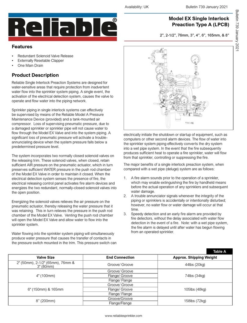
Reliable Single Interlock Preaction Systems are designed for
water-sensitive areas that require protection from inadvertent
water flow into the sprinkler system piping. A single event, the
activation of the electrical detection system, causes the valve
to operate and flow water into the piping network.
Sprinkler piping in single interlock systems can effectively
be supervised by means of the Reliable Model A Pressure
Maintenance Device (provided) and a tank-mounted air
compressor. Loss of supervising pneumatic pressure, due to
a damaged sprinkler or sprinkler pipe will not cause water to
flow through the Model EX Valve and into the system piping. A
significant loss of pneumatic pressure will activate a trouble-
annunciating device when the system pressure falls below a
predetermined pressure level.
The system incorporates two normally closed solenoid valves
on the releasing trim. These solenoid valves, when closed,
retain sufficient AIR pressure on the pneumatic actuator, which
in turn preserves sufficient WATER pressure in the push rod
chamber of the Model EX Valve in order to maintain it closed.
When the electrical detection system senses the presence of
fire, the electrical releasing control panel activates fire alarm
devices and energizes the two redundant, normally-closed
solenoid valves into the open position.
Energizing the solenoid valves relieves the air pressure on the
pneumatic actuator, thereby releasing the water pressure that
it was retaining. This in turn relieves the pressure in the push
rod chamber of the Model EX Valve. Venting the push rod
chamber will open the Model EX Valve and allow water to flow
into the sprinkler system.
Water flowing into the sprinkler system piping will
simultaneously produce water pressure that causes the
transfer of contacts in the pressure switch mounted in the trim.
www.reliablesprinkler.com
This pressure switch can electrically initiate the shutdown or
startup of equipment, such as computers or other second
alarm devices. The flow of water into the sprinkler system
piping effectively converts the dry system into a wet pipe
system. In the event that the fire subsequently produces
sufficient heat to operate a fire sprinkler, water will flow from
that sprinkler, controlling or suppressing the fire.
The major benefits of a single interlock preaction system,
when compared with a wet pipe (deluge) system are as
follows:
1. A fire alarm sounds prior to the operation of a sprinkler,
which may enable extinguishing the fire by handheld
means before the actual operation of any sprinklers and
subsequent water damage.
2. A trouble annunciator signals whenever the integrity of
the piping or sprinklers is accidentally or intentionally
disturbed; however, no water flow or water damage will
occur at that time.
3. Speedy detection and an early fire alarm are provided
by fire detectors, without the delay associated with water
flow detection in the event of a fire. Note: with a wet pipe
system, the fire alarm is delayed until after water has
begun flowing from an operated sprinkler.
Valve Size End Connection Approx. Shipping Weight
2" (50mm), 2-1/2" (65mm), 76mm &
3" (80mm) Groove/ Groove 44lbs (20kg)
4" (100mm)
Groove/ Groove
74lbs (34kg)Flange/ Groove
Flange/ Flange
6" (150mm) & 165mm
Groove/ Groove
105lbs (48kg)Flange/ Groove
Flange/ Flange
8” (200mm) Groove/Groove 158lbs (72kg)
Flange/Flange
Table A
Bulletin 739 June 2020
Model EX Single Interlock
Preaction Type A (LPCB)
2”, 2-1/2”, 76mm, 3”, 4”, 6”, 165mm, & 8”
Availability: UK

Model EX Single Interlock Preaction System Type A Technical Data
Technical Specifications
Pressure Rating:
175 psi (12,1 bar)
Minimum Water Supply Pressure:
20psi (1,4 bar)
Minimum Water Supply Temperature:
40°F (4°C)
Maximum Water Supply Temperature:
140°F (60°C)
Factory tested to hydrostatic pressure of 500 psi (34.5 bar)
Listings and Approvals
LPCB
End Connections
See Table A
Specifications
Groove: ANSI/AWWA C606
Flange: ASME B 16.5 or ISO 7005-2 PN16
Thread: ANSI B1.20.1
Valve Size End
Connection A B C D E F G H I
2" (50mm)
Groove/Groove 12-1/2
(318)
5-1/2
(140)
31-1/2
(800)
4-1/4
(108)
14-1/2
(368)
9-7/8
(251)
7
(178)
8-1/2
(216)
8-3/8
(213)
2-1/2" (65mm)
76mm
3" (80mm)
4" (100mm)
Groove/Groove 14
(356) 5-1/2
(130)
33-3/8
(848)
5-1/2
(140)
16
(406)
11
(279)
8
(203)
8-1/2
(216)
10
(254)
Flange/Groove 16
(406)
Flange/Flange
6" (150mm)
&
165mm
Groove/Groove 16
(406) 4-7/8
(124)
34-5/8
(880)
5-1/2
(140)
16-1/2
(419)
11-5/8
(295)
8-5/8
(219)
8-1/2
(216)
10-1/2
(267)
Flange/Groove 19
(483)
Flange/Flange
8" (200mm)
Groove/Groove 19-3/8
(492) 4-5/8
(117)
34-1/8
(867)
5-1/2
(140)
17
(432)
13-5/8
(346)
9-1/8
(232)
8-1/2
(216)
11-3/4
(298)
Flange/Flange 21-1/4
(540)
Installation Dimensions in Inches (mm) Table B
Bulletin 739
June 2020
Page 2 of 9
www.reliablesprinkler.com
Model EX Type A Dimensions Figure 1

At the heart of Reliable’s Single Interlock Preaction System is the
Model EX Valve. This valve is a hydraulically operated, straight-
through-design, differential-type valve (see Fig. 2). System
maintenance is simplified since priming water is not required and
the deluge valve can be reset externally without cover removal.
This is accomplished by pushing in and turning the external
reset knob at the rear of the valve (see Fig. 2). This feature
provides a significant system-restoration time advantage.
The Reliable Single Interlock Preaction System trim set (see Fig.
2) provides all of the necessary equipment for connections to the
valve’s pushrod chamber inlet and outlet ports, the main drain,
alarm devices, air supply, water supply, and required pressure
gauges. This valve is provided fully assembled with trim.
System Operation
To fully operate a Reliable Single Interlock Preaction System, two
independent events must coexist before water is discharged.
One electrical detector (two detectors in a cross-zoned system)
must activate and a sprinkler must open. Operation of the
detection system will cause the valve to open, but no water will
discharge since the sprinklers will not have opened. Opening of
a sprinkler in the absence of a detection signal will result in loss
of air or nitrogen pressure and activation of a low pressure alarm.
When set correctly for service, the Model EX Valve is
hydraulically established to withhold the supply water from the
sprinkler system piping. The Reliable Model EX Valve is shown in
both closed and open positions in Fig.2. In the closed position,
the supply pressure acts on the underside of the clapper and
also on the push rod through the push rod chamber’s inlet
restriction. The resultant force due to the supply pressure acting
on the push rod is multiplied by the mechanical advantage of
the lever and is more than sufficient to hold the clapper closed
against normal supply pressure surges.
When a fire is detected, the energized solenoid valves vent the
air from the pneumatic actuator, which in turn vents the push rod
chamber to atmosphere through the chamber’s outlet. Since
the pressure cannot be replenished through the inlet restriction
as rapidly as it is vented, the pushrod chamber pressure
falls instantaneously. When the pushrod chamber pressure
approaches approximately one-third of the supply pressure, the
upward force of the supply pressure acting beneath the clapper
overcomes the lever-applied force thereby opening the clapper.
Once the clapper has opened, the lever acts as a latch,
preventing the clapper from returning to the closed position.
Water from the supply flows through the EX Valve into the system
piping. Water also flows through the dry pipe alarm outlet to the
alarm devices.
After the system is shut down and drained, the Model EX valve
can be reset by pushing in and turning the reset knob at the
rear of the valve (see Fig.2). The external reset feature of the
Model EX Valve provides a means for simple, economical system
testing, which is one essential facet of a good maintenance
program.
The external reset feature does not, however, eliminate another
important facet of good maintenance, namely, periodic cleaning
and inspection of the internal valve parts. In the event that water
builds up inside the valve due to condensate from the air supply
system or water left inside from valve system testing, a drain is
available for venting. After closing the main supply valve, a small
valve over the drain cup can be opened slightly until the water
inside the valve body and the main pipe column has drained.
See the section titled “Draining Excess/Condensate Water From
System” in this bulletin for the detailed procedure.
The Model B Manual Emergency Station is also included in the
trim set. It consists of an aluminum nameplate mechanically
attached to a ball valve. The valve handle in its OFF position
is guarded against accidental turning to the ON position (and
system discharge) by a nylon cable tie provided with each trim
kit. The cable tie is inserted, after the system has been restored
for operation. The nylon cable tie is designed to allow, in case
of an emergency, forceful turning of the valve handle to the ON
position. As an alternative to the Model B Hydraulic Manual
Emergency Station, the Model A Hydraulic Manual Emergency
Pull Box (see Reliable Bulletin 506) is also available and can be
provided as an option.
Whenever ambient temperature conditions are high, the water
temperature in the Model EX Valve’s pushrod chamber could
possibly increase, thereby increasing the pressure in the
chamber to values exceeding the rated pressure of the system.
In an installation where standard temperatures are exceeded,
a pressure relief kit may be needed. Pressure relief kit, P/N
6503050001, can be installed into the pushrod chamber’s
releasing line to limit the pressure to 175 psi (12,1 bar).
Bulletin 739
June 2020
Page 3 of 9
www.reliablesprinkler.com
Model EX Type A Section and Rear Views Figure 2

System Design Considerations
The automatic sprinklers, air compressor, releasing devices,
electric releasing control equipment, fire detection devices,
manual pull stations, and signaling devices which are utilized
with this Reliable Single Interlock Preaction System must be Loss
Prevention Certification Board (LPCB) approved, as applicable.
The system valve and all interconnecting piping must be located
in a readily visible and accessible location and in an area that
can be maintained at a minimum temperature of 40°F (4°C). Note:
Heat tracing is not permitted.
The redundant solenoid valves are operated and supervised by
an electrical releasing/control panel.
System Air Pressure Requirements
When a Reliable Single Interlock Preaction System is utilized,
the sprinkler system piping requires a minimum of 7 psi (0,5
bar) supervisory pneumatic pressure. The Model A Pressure
Maintenance Device, along with an additional air pressure
regulator, are used to maintain the system pneumatic pressure
between 7 and 10 psi (0,5 and 0,7 bar) where a dry nitrogen gas
supply or a clean, dependable, and continuous (24 hours per
day, 7 days per week) compressed air source is available.
The section of the preaction trim that contains the two redundant
normally-closed solenoid valves, and the supply to the pneumatic
actuator require pneumatic pressure settings per Table C. When
establishing the preaction system for service, refer to Table C
of this bulletin for the correct pneumatic pressure settings for a
corresponding water supply pressure.
Note: During the initial system set-up, a higher pneumatic
pressure may be required in order to properly seat the internal
diaphragm of the pneumatic actuator.
Refer to Reliable Bulletin 251 for instructions on how to modify
these pressure settings.
Bulletin 739
June 2020
Page 4 of 9
www.reliablesprinkler.com
Water Pressure
psi (bar)
Pneumatic Pressure to be Pumped
into Sprinkler System, psi (bar)
Maximum Not Less Than Not More Than
20 (1.4) 10 (0.7) 14 (0.9)
50 (3.4) 12 (0.8) 16 (1.1)
75 (5.2) 13 (0.9) 17 (1.2)
100 (6.9) 15 (1.0) 19 (1.3)
125 (8.6) 16 (1.1) 20 (1.4)
150 (10.3) 17 (1.2) 21 (1.4)
175 (12.1) 18 (1.2) 22 (1.5)
System Pressure Table C
System Electrical Requirements
All releasing, alarm and detection devices in this Reliable Single
Interlock Preaction System are supervised by the Preaction
Panel Series 1000 MK4. The power supply, the standby
emergency power supply, battery charger, and the rectifier
circuitry are all contained within this panel. For additional and
detailed wiring information, refer to the manufacturer’s literature
included with the Releasing Control Panel.
Note: In order for the solenoid valve to maintain Reliable
warranty it must remain sealed as it came from the factory. If
there are concerns about the valve’s internal components,
immediate replacement is recommended.
Valve Size:
Equivalent Length:
Cv
C = 120 C = 100
2" (50mm) 4.4 ft (1,3 m) 3.1 ft (1,0 m) 101
2-1/2" (65mm) 6.0 ft (1,8 m) 4.3 ft (1,3 m) 236
76mm 7.7 ft (2,3 m) 5.5 ft (1,7 m) 241
3" (80mm) 12.6 ft (3,8 m) 9.0 ft (2,7 m) 254
4" (100mm) 14 ft (4,3 m) 10 ft (3,0 m) 469
165mm 29.4 ft (9,0 m) 20.9 ft (6,4 m) 886
6" (150mm) 29.4 ft (9,0 m) 20.9 ft (6,4 m) 886
8" (200mm) 53.5 ft (16,3 m) 38.1 ft (11,6 m) 1516
Friction Loss Table D

Single Interlock Preaction System Air Pressure Settings Figure 3
Bulletin 739
June 2020
Page 5 of 9
www.reliablesprinkler.com

Bulletin 739
June 2020
Page 6 of 9
www.reliablesprinkler.com
Model EX Type A Components Figure 4

Resetting the Model EX Single Interlock
System (Ref. Fig. 5)
1. Close the valve controlling water supply to the Model EX
Valve and close the air or nitrogen supply to the sprinkler
system.
2. Close the pushrod chamber supply valve.
3. Open main drain valve and drain system. Close main drain
valve.
4. Open all drain valves and vents at low points throughout
the system, closing them when flow of water has stopped.
5. Open the Manual Emergency Station to relieve pressure in
the pushrod chamber of the Model EX Valve.
6. With the alarm line valve open, push in the plunger of ball
drip valve, forcing the ball from its seat, and drain the alarm
line. Close the alarm line valve.
7. With the Manual Emergency Station open, push in and rotate
the Model EX Valve external reset knob counterclockwise
(when facing the valve), until you hear a distinct noise
indicating that the clapper has reset. Note: The reset knob
can be rotated only while pressure in the pushrod chamber
is vented to atmospheric condition (0 psig) in step 5.
8. Inspect and replace any portion of the detection system
and/or sprinkler system subjected to fire conditions.
9. Confirm that solenoid valves are de-energized and closed.
10. Open the air or nitrogen supply quick fill valve to restore
supervisory pressure in the sprinkler system and close
the pneumatic actuator. Allow the pressure to build to the
level specified in Table A, then set the pneumatic supply to
automatic operation.
11. Open the main drain approximately two turns.
12. Open the pushrod chamber supply valve.
13. Slightly open the main control valve until water can just be
heard running out the main drain.
14. Slowly close the main drain, directing water to the Manual
Emergency Release. Allow water to flow through the
Manual Emergency release to purge air from the pushrod
chamber. Note: Venting of air from the pushrod chamber
is very important to ensure proper system operation and
avoid false tripping of the Model EX Valve.
15. Upon seeing a solid flow of water from the drain tubing,
close the Manual Emergency Release valve. Allow
pressure to build below the Model EX Valve clapper.
16. Open the alarm line valve. If no leak occurs, the Model EX
Valve clapper is sealed.
17. Slowly open the main valve controlling water supply until
fully open and verify that it is properly monitored.
18. Verify that the pushrod chamber supply valve and alarm
line valve are open. The pushrod chamber supply valve
must remain open when the Model EX Valve has been
reset to maintain water pressure in the pushrod chamber.
19. Verify that the Manual Emergency Station is secured in the
OFF position with the appropriate nylon tie.
Inspection and Testing
1. Water supply — Confirm that valves controlling water
supply to the EX Valve are opened fully and properly
monitored.
2. Alarm line — Confirm that the alarm line valve is open and
remains in this position.
3. Other trim valves — Confirm that the pushrod chamber
supply valve is open, as well as all pressure gauge valves.
The main drain valve, condensate drain valve, and alarm
test valve should be closed.
4. Ball drip valve — Push in on the plunger to be sure ball
check is off its seat. If no water appears, the Model EX
Valve water seat is tight. Inspect the bleed hole on the
underside of the pushrod chamber for leakage.
5. Supervisory pneumatic pressure — Inspect actuation
piping and system air (or nitrogen) pressure for
conformance to Table A.
6. Releasing device — Check outlet of the releasing devices
(i.e., hydraulic manual emergency station and solenoids)
for leakage. Also verify that tubing drain lines from releasing
devices are not pinched or crushed which could prevent
proper releasing of the EX Valve.
7. Testing alarms — Open the alarm test valve permitting
water from the supply to flow to the electric sprinkler
alarm switch and to the mechanical sprinkler alarm (water
motor). After testing, close this valve securely. Push in on
the plunger of ball drip valve until all water has drained
from the alarm line.
8. Operational test — Open the Model B Manual Emergency
Station. Alternatively, deplete pneumatic pressure from the
sprinkler system. Note: AN OPERATIONAL TEST WILL
CAUSE THE MODEL EX VALVE TO OPEN AND FLOW
WATER INTO THE SPRINKLER SYSTEM.
9. Secure the Model B Manual Emergency Station in the OFF
position with nylon tie after EX Valve is reset.
Testing Detection System Without Operating
Model EX Valve
1. Close the valve controlling water supply to the system
valve and open the main drain valve.
2. Verify that valve supplying hydraulic pressure to the piston/
pushrod chamber is open, allowing water to enter the
pushrod chamber.
3. Deplete pneumatic pressure from the sprinkler system.
4. Loss of pneumatic pressure must result in a sudden drop
of water pressure in the pushrod chamber, as indicated by
the pressure gauge on the hydraulic release trim.
5. Reset the valve per the reset instructions.
7.
Bulletin 739
June 2020
Page 7 of 9
www.reliablesprinkler.com

Maintenance
The owner is responsible for maintaining the fire protection system
in proper operating condition. Any system maintenance or testing
that involves placing a control valve or detection/control system
out of service may eliminate the fire protection that is provided by
the fire protection system.
The Reliable Model EX valve and associated equipment shall
periodically be given a thorough inspection and test. NFPA
25, “Inspection, Testing, and Maintenance of Water Based
Fire Protection Systems,” provides minimum maintenance
requirements. System components shall be tested, operated,
cleaned, and inspected at least annually, and parts replaced
as required. Replace any components found to be corroded,
damaged, worn, or non-operable. Increase the frequency of
inspections when the valve is exposed to corrosive conditions
or chemicals that could impact materials or operation of the
assembly.
If face plate is removed during maintenance, torque face plate
bolts to the following values during re-installation:
• 35 ft-lbs. (47 N-m) for 2” through 4” valves
• 70 ft-lbs. (95 N-m) for 6”-8” valves
Draining Excess/Condensate Water from the System
1. Notify the owner and monitoring company that maintenance
is being performed on the system.
2. Close the main water control valve.
3. Open the Main Drain Valve.
4. Open the Condensate Drain Valve until all water has drained.
5. Close Condensate Drain Valve.
6. Partially open the Main Water Control Valve.
7. Slowly close the Main Drain Valve.
8. Fully open the Main Water Control Valve.
9. Notify the owner and monitoring company that the system
has been returned to service.
Clapper Gasket and Seat Replacement Procedure
1. Disable detection system and supervisory pneumatic
supply to system.
2. Shut down the valve controlling the water supply to
the system and open the main drain valve. Open the
condensate drain valve. Close the pushrod chamber supply
valve and open the Model B Manual Emergency Station.
3. Remove the EX Valve front (handhold) cover and inspect
the seat, clapper, and seal assembly for damage. If
inspection indicates damage to the seal assembly only,
replace as follows:
4. Remove the bumpstop nuts and remove the seal assembly
. Install a new seal assembly and thread the bumpstop
nuts onto the threaded studs of the seal assembly. Tighten
finger tight plus ¼ to ½ turn.
5. If inspection indicates damage to the clapper, proceed to
step 6.
6. At the rear of the valve, disconnect the condensate drain
trim section starting with the elbow connector. Then remove
the ¼” globe valve, followed by the ¾”x¼” reducing
bushing. Remove the retaining rings from the clapper hinge
pin, push the hinge through the condensate drain opening
and remove the clapper subassembly. Install a new clapper
subassembly in the reverse order making sure the clapper
spacers are in their proper position.
7. If the seat is damage, or it is suspected that the leakage is
through the seat O-rings, proceed to step 8.
8. Using Reliable P/N 6881603000 Seat Wrench for 2”
(50mm), 2½” (65mm), 76mm and 3” (80mm) valve sizes,
Reliable P/N 6881604000 for 4” (100mm) valve size,
Reliable P/N 6881606000 for the 6” (150mm) and 165mm
valve sizes or Reliable P/N 6881608000 Seat Wrench for 8”
(200mm) valve size, remove the seat by unscrewing. This
will loosen the seat-clapper-mounting ring subassembly.
8.
Bulletin 739
June 2020
Page 8 of 9
www.reliablesprinkler.com
Solenoid Valve
WARNING: The owner is responsible for maintaining the
fire protection system in proper operating condition. Any
system maintenance or testing that involves placing a control
valve or detection system out of service may eliminate the
fire protection of that system. Prior to proceeding, notify
all authorities having jurisdiction. Consideration should be
given to employment of a fire patrol in the affected area.
WARNING: Prior to operating the solenoid valve,
be sure to close the system control valve to avoid
unintentional operation of the system.
1. Inspections: It is imperative that the system be inspected
and tested in accordance with NFPA 25 on a regular
basis. The frequency of the inspections may vary due to
contaminated water supplies, corrosive water supplies,
or corrosive atmospheres. In addition, the alarm devices,
detection systems, or other connected trim may require a
more frequent schedule. Refer to the system description
and applicable codes for minimum requirements.
2. The valve must be inspected at least monthly for cracks,
corrosion, leakage, etc., cleaned and replaced as necessary.
3. If leakage is suspected through the solenoid
valve, it should be replaced.
Troubleshooting
1. Mechanical sprinkler alarm not operating: This is most
likely caused by a clogged screen in the strainer of the
water motor. Proceed as follows: Remove plug from the
strainer. Remove and clean the screen. Replace the screen
and the plug, and then tighten securely (Ref. Bulletin 613).
2. Water leaking from Ball Drip. This can be
caused by either a water column on top of
the clapper or a supply water leakage.
a. Leakage due to water column. This condition is
caused by leakage past the clapper seal assembly. Be
sure the clapper seal and seat are free of any type of
debris or damage. If necessary, follow steps below to
replace the seal assembly and/or seat.
b. Supply water leakage. This condition is caused by
leakage past the lower seat O-ring. Follow steps below
for inspection and/or replacement of lower seat O-ring.
3. Air or nitrogen leaking from Ball Drip. This
condition is caused by leakage past either the
clapper seal assembly or the upper seat O-ring.
a. Clapper seal leak. Be sure the clapper seal and
seat are free of any type of debris or damage. If
necessary, follow steps below to replace the seal
assembly and/or seat.
b. Upper seat O-ring. Follow steps below for
inspection and/or replacement of upper seat O-ring.

Listing & Approvals
The LPCB approval for Single Interlock Preaction systems
states the system must comply with the general requirements
of the “LPC Rules for Automatic Sprinkler Systems (incorporat-
ing EN12845)” and in particular Technical Bulletin 208 “Sup-
plementary requirements for sprinkler installations which can
operate in the dry mode”.
Loss Prevention Certification Board (LPCB)
Installation Requirements of Preaction Systems Include:
1. The equipment must be installed, configured and
maintained in accordance with the manufacturers
specifications, by appropriately trained personnel.
2. The system shall be electrically monitored and be capable
of indicating “ready to operate” at all times.
3. Detectors should be LPCB approved and must be
compatible with the Control Panel.
4. Connecting cables shall comply with BS6387 (classification
C, W, Z).
5. Two LPCB approved Solenoid Valves shall be installed in
parallel, shall function in the pneumatic condition only and
be protected by a strainer.
6. Clean dry air (or Nitrogen) shall be used. An air
maintenance device shall be used, such that the inflow of
air cannot exceed the egress of air through one sprinkler,
or any other means of operating the valve.
9.
Clapper Gasket and Seat Replacement Procedure (cont.)
8 (cont). Reach into the valve and grasp the seat and remove
it from the valve. Then remove the clapper-mounting
ring subassembly from the valve. Visually examine all
componentsoftheseat-clapper-mountingringsubassembly
replacing any component that appears damaged. New
O-rings should always be used for reassembly.
9. Reassembly: clean the bore of the valve body. Lubricate the
bore with O-ring grease. Lubricate and install the O-rings
onto the seat. Lubricate and install the mounting ring
O-ring into the body (8” (200mm) valve size only). Insert
the clapper-mounting ring subassembly into the handhold
opening of the EX Valve using caution to not damage or
dislodge the mounting ring O-ring (8” (200mm) valve size
only). Align the mounting ring so that the Lever is near
the pushrod and the mounting ring “ears” are between
the tabs of the valve body. Insert the seat into the valve
body and through the clapper-mounting ring subassembly.
Start to tread the seat into the body by hand, then tighten
the seat with the seat wrench until it bottoms out on the
mounting ring. Verify that the seat-clapper-mounting ring
subassembly is in the fully down position between the tabs
of the body, and check to see that the lever lines up with
the pushrod. Reassemble the handhold cover and set up
the Model EX Valve as per the section “Resetting Model EX
Valve Single Interlock Preaction Systems”.
Pushrod Chamber Diaphragm and O-Ring Replacement
Procedure
A small bleed hole is located on the underside of the pushrod
chamber. If there is air or water leakage coming out of the bleed
hole:
a. Disable detection system and supervisory pneumatic
supply to system.
b. Shut down the valve controlling water supply to the system.
Relieve the inlet pressure by opening the main drain valve.
Close the valve that supplies water to the pushrod chamber,
and open the Model B Manual Emergency Station.
c. Remove the trim at the unions nearest to the pushrod
chamber cover.
d. Take the pushrod chamber cover off by removing the six
retaining screws.
CONDITION ONE (Water coming out of the bleed
hole):
Water coming out of the bleed hole is caused by a leaking
diaphragm. Visually inspect the pushrod chamber cover and
piston to determine what could have damaged the diaphragm
and then correct. Install a new diaphragm. NOTE: The
diaphragm has two different surfaces; it is not bi-directional.
It will fail if installed backwards! Roll the diaphragm so that
the smooth surface (the pressure side) conforms to the inside
of the pushrod chamber cover and the fabric side engages
the pushrod, and reassemble the six retaining screws with an
installation torque of 15 foot-pounds in a star pattern. Set up the
Model EX Valve as per the section “Resetting Model EX Valve
Single Interlock Preaction Systems”.
CONDITION TWO (System Air coming out of the
bleed hole):
System air coming out of the bleed hole is caused by a
worn O-ring assembled to the pushrod guide. Remove the
piston-pushrod subassembly, pushrod spring, and pushrod
guide. installation torque for the pushrod guide is 35 inch-
pounds. CAUTION: Do not over tighten the pushrod guide.
Reassemble the components that were initially removed.
Re-install the diaphragm if it appears to be in good shape,
otherwise, replace it also. NOTE: The diaphragm has two
different surfaces; it is not bi-directional. It will fail if installed
backwards! Roll the diaphragm so that the smooth surface
(the pressure side) conforms to the inside of the pushrod
chamber cover and the fabric side engages the pushrod, and
reassemble the six retaining screws with an installation torque
of 15 foot-pounds in a star pattern. Set up the Model EX Valve
as per the section “Resetting Model EX Valve Single Interlock
Preaction Systems”.
Ordering Information
Specify:
Model EX Single Interlock Preaction System Type A
• Size
• 2” (50mm)
• 2-1/2” (65mm)
• 3” (80mm)
• 76mm
• 4” (100mm)
• 6” (150mm)
• 165mm
• 8” (200mm)
• End Configuration
• See Table A
Bulletin 739
June 2020
Page 9 of 9
www.reliablesprinkler.com
Table of contents
Other Reliable Control Unit manuals