The Reliable Model B-SI/C-SI Air Compressor Panel shall pe-
riodically be given a thorough inspection and test. NFPA 25,
“Inspection, Testing, and Maintenance of Water Based Fire
Protection Systems,” provides minimum maintenance require-
ments. System components shall be tested, operated, cleaned
and inspected at least annually and parts replaced as required.
Listings and Approvals
Underwriters Laboratories, Inc. and UL Canada (cULus)
Listing Category: Air Pressure Maintenance Devices, Automatic
Guide Number: VIOT
FM Approved
Guarantee
For Reliable Automatic Sprinkler Co., Inc. guarantee, terms, and
conditions, visit www.reliablesprinkler.com.
Ordering Information
Specify:
• Model B-SI Air Compressor Panel (P/N 6702010003)
(120 VAC)
• Model C-SI Air Compressor Panel (P/N 6702020003)
(220 VAC)
Application
The Reliable Model B-SI and C-SI Air Compressor Panels are
designed and listed for use in installations governed by NFPA
13 to provide and supervise the air pressure required for single
interlock preaction systems. A 200 gallon system can be filled
in approximately 30 minutes. A bypass is provided for quickly
filling larger systems.
The Model B-SI and C-SI Air Compressor Panels should not be
used with dry pilot single interlock preaction systems. These
systems require substantially more air pressure than wet pilot or
electrically actuated systems. Refer to manufacturers informa-
tion for appropriate air supply for dry pilot actuated systems.
Installation
Location must be coordinated with, and installation made in ac-
cordance with, the requirements of NFPA 13 or NFPA 13R, and all
authorities having jurisdiction.
Check valve included with hose kit must be installed in the hori-
zontal position.
All electrical work must be performed in accordance with appli-
cable local and national codes.
Maintenance
The owner is responsible for maintaining all parts of the fire pro-
tection system in proper operating condition. Any system main-
tenance or testing that involves placing a system component
out of service may eliminate the fire protection that is provided
by the fire protection system.
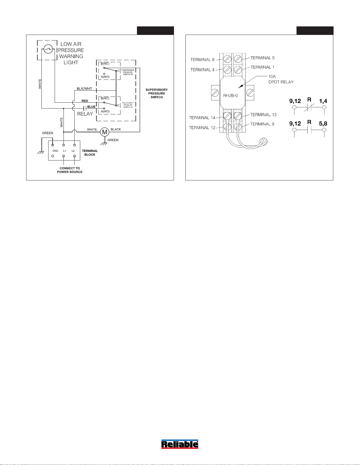
Note: Relay contacts shown in alarm/loss of power condition for
remote monitoring.
Bulletin 252
May 2019
Page 3 of 3
www.reliablesprinkler.com
Figure 3Figure 2
P/N 9999970120
Wiring Diagram Relay Diagram