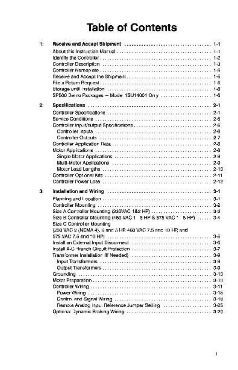
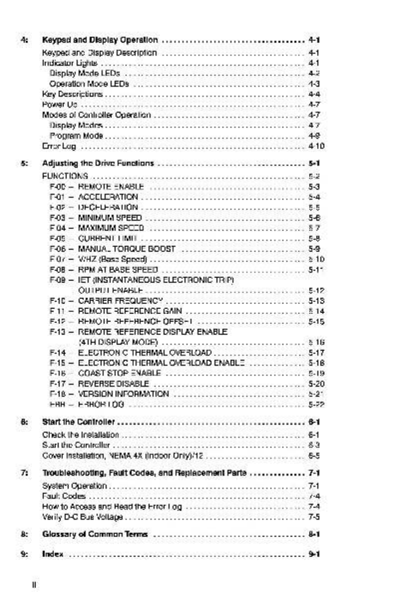
Reliance electric SP500 User manual

Installation
and
Operation
Manual
for
the
SP500
A-C
VxS®
Controller
Three-Phase
Input
and
Three-Phase
Output
1/4-5
HP
@
200-230
VAC,
1/4-10
HP
@
380-460
VAC
and
1/4
-10
HP
@
575
VAC
NEMA
1
NEMA
4X
(Indoor
Only)/12
woae
Instruction
Manual
D2-3267-1
PEN
ELECTRIC&L/

DANGER
ONLY
QUALIFIED
ELECTRICAL
PERSONNEL
FAMILIAR
WITH
THE
CONSTRUCTION
AND
OPERATION
OF
THIS
EQUIPMENT
AND
THE
HAZ-
ARDS
INVOLVED
SHOULD
INSTALL,
ADJUST,
OPERATE,
AND/OR
SERVICE
THIS
EQUIPMENT.
READ
AND
UNDERSTAND
THIS
MANUAL
IN
ITS
ENTIRETY
BEFORE
PROCEEDING.
FAILURE
TO
OBSERVE
THIS
PRECAUTION
COULD
RESULT
IN
SEVERE
BODILY
INJURY
OR
LOSS
OF
LIFE.
VxS®
and
Reliance®
are
registered
trademarks
of
Reliance
Electric
Industrial
Company
or
its
subsidiaries.
®
Copyright,
Reliance
Electric
Industrial
Company,
1993

Table
of
Contents
Receive
and
Accept
Shipment
...........-00:e
eee
eeee
eee
eeeeeeee
1-1
About
this
Instruction
Manual
........0...0
0.0000
c
cece
eee eee
eee
eee
1-1
Identify
the
Controller...
0.0...
ee
1-2
Controller
Description
..........
0c.
c
eee
eee
1-3
Controller
Nameplate
...........
0.
cece
eee
teens
1-5
Receive
and
Accept
the
Shipment..................
0c
cece
e
eee
eee eee
1-5
File
a
Return
Request...
0.6...
eee
eee
1-6
Storage
until
Installation
2.0...
6.
eee
1-6
SP500
Demo
Packages
—
Model
1SU14001
Only
....................-
1-6
Specifications
.......
00...
cee
eee
eee eee
eee
2-1
Controller
Specifications
........
0.00...
eee
eee
2-1
Service
Conditions
..........
0...
c
cece
eens
2-5
Controller
Input/output
Specifications
.............
0...
e
eee
eee
2-6
Controller
InputS
...........
0.
eee
ee
teens
2-6
Controller
OutputS
...........
cece
teens
2-7
Controller
Application
Data
.............
0.
e
cece
eee
2-8
Motor
Applications
......
0.0.0...
.
cece
eee
2-8
Single-Motor
Applications
...........
00...
c
eee
eee
eee eee
2-9
Multi-Motor
Applications
.......0....
00...
cece
eee
2-9
Motor
Lead
Lengths
.........
0...
cece
eee
eens
2-10
Controller
Optional
Kits
0.0.2...
0...
cece
eee
2-11
Controller
Power
LOSS
........
0.00
cece
eee
eee
eee
eee
eee
2-12
Installation
and
Wiring
........
ccc
cee
eee
e
eee
eee
3-1
Planning
and
Location
........
0.0...
ccc
eee
eens
3-1
Controller
Mounting
..........
0.0
cece
eee
eee
eee
3-2
Size
A
Controller
Mounting
(230VAC
182
HP)
..............0:e
ee
eee eee
3-2
Size
B
Controller
Mounting
(460
VAC
1-5
HP
&
575
VAC
1-5
HP)
......
3-4
Size
C
Controller
Mounting
(230
VAC
2
(NEMA
4),
3
and
5
HP
460
VAC
7.5
and
10
HP,
and
575
VAC
7.5
and
10
HP)
.........
cece
eens
3-5
Install
an
External
Input
Disconnect
............
0...
ee
eee
3-6
Install
A-C
Branch
Circuit
Protection
.............-..
0c
cece
3-7
Transformer
Installation
(If
Needed)
.......
0.0...
cee
eee eee
eee
eee
3-9
Input
Transformers
........
0... cece
eens
3-9
Output
Transformers
..........
0.2
ec
eect
teens
3-9
Grounding
.....
0.
eee
eee
3-10
Motor
Preparation
....
0...
eee
3-10
Controller
Wiring
....
0...
eee
tees
3-11
Power
Wiring
2.0...
eee
eee
3-15
Control
and
Signal
Wiring
...........
0...
eee
eee
eee
3-18
Remote
Analog
Input
Reference
Jumper
Setting
...................-
3-25
Optional
Dynamic
Braking
Wiring
...........
0.00
c
eee
eee
eee
3-26

Keypad
and
Display
Operation
...........200ceeeeee
eee
e
ee
eeeee
4-1
Keypad
and
Display
Description
............
0...
cece
eee
4-1
Indicator
LightS
........
0...
ccc
ccc
eee
tenets
4-1
Display
Mode
LEDS
........
0...
cc
cece
cette
eens
4-2
Operation
Mode
LEDS
.........
2... cece
eee eee
eee
eens
4-3
Key
Descriptions
....
0...
eee
eens
4-4
Power
Up
....
0.
eee
eee een
eee
ee
4-7
Modes
of
Controller
Operation
...........
0000
eee
eee
eens
4-7
Display
MOdeéS
.......
0...
eee
4-7
Program
Mode...
1...
cece
eee
eee
eee
4-9
Lg
co)
a
©
4-10
Adjusting
the
Drive
Functions
...............
cece
scene
eee
eee
e
eens
5-1
FUNCTIONS
.........
0.
cece
eee
tee
eee
tenes
5-2
F-00
—
REMOTE
ENABLE
............
2.0
e
cece
eee
ener
eens
5-3
F-01
—
ACCELERATION
............
2
cece
cece
eee
eee
5-4
F-02
—
DECELERATION
............
2.
cece
eee
eee
eee
5-5
F-03
—
MINIMUM
SPEED
.............
0...
c
cette
eee
eee
5-6
F-04
—
MAXIMUM
SPEED
............
0.000
cece
5-7
F-O5
—
CURRENT
LIMIT
..............
0c
eee
eee
ee
eee
5-8
F-06
—
MANUAL
TORQUE
BOOST
..............
cece
eee
eee
5-9
F-07
—
V/HZ
(Base
Speed)
...........
eee eee
tees
5-10
F-08
—
RPMAT
BASE
SPEED
.............00
00
eee
eens
5-11
F-09
—
IET
(INSTANTANEOUS
ELECTRONIC
TRIP)
OUTPUT
ENABLE
..........00.
eee
cece
eee
5-12
F-10
—
CARRIER
FREQUENCY
..........
0.0000
e
eee
eee
5-13
F-11
—
REMOTE
REFERENCE
GAIN
...............
00
c
eee eee
eee
5-14
F-12
—
REMOTE
REFERENCE
OFFSET
..............000e
eee
eeeeee
5-15
F-13
—
REMOTE
REFERENCE
DISPLAY
ENABLE
(4TH
DISPLAY
MODE)
...........00.
0.
cece
eee
ee
eee
eee
5-16
F-14
—
ELECTRONIC
THERMAL
OVERLOAD
.............--++22
eee
5-17
F-15
—
ELECTRONIC
THERMAL
OVERLOAD
ENABLE
.............-
5-18
F-16
—
COAST
STOP
ENABLE
..........
0.0000
e
eee
eee
5-19
F-17
—
REVERSE
DISABLE
............
0.000
c
eee eee
eee
eee
5-20
F-18
—
VERSION
INFORMATION
...........-.0:
cece
eee
eee
5-21
ERR
—
ERRORLOG
..........
0c
cee
eee
eee
eens
5-22
Start
the
Controller
............
ccc eee
eee eee
eee
eee
eens
6-1
Check
the
Installation
..........
0.00.
cee
eee
6-1
Start
the
Controller
..........
0...
cece
eee
6-3
Cover
Installation,
NEMA
4X
(Indoor
Only)/12
..............0::
eee
eee
6-5
Troubleshooting,
Fault
Codes,
and
Replacement
Parts
..............
7-1
System
Operation
..........
0... cece
eee
eee
eee
7-1
Fault
Codes
.......
0...
eee
eect
eee
ttt
neeee
7-4
How
to
Access and
Read
the
Error
Log
.........
cece
cece
7-4
Verify
D-CBus
Voltage...
66.
7-5
Glossary
of
Common
Terms
.............0c0se
eee
e
cece
eee
eee eee
8-1
La:
=>,
Qe
9-1

Figure
1-1.
Figure
1-2.
Figure
2-1.
Figure
3-1.
Figure
3-2.
Figure
3-3.
Figure
3-4.
Figure
3-5.
Figure
3-6.
Figure
3-7.
Figure
3-8.
Figure
3-9.
Figure
3-10.
Figure
3-11.
Figure
3-12.
Figure
3-13.
Figure
3-14.
Figure
3-15.
Figure
3-16.
Figure
3-17.
Figure
3-18.
Figure
3-19.
Figure
4-1.
Figure
5-1.
Figure
5-2
Figure
5-3.
Figure
7-1.
Figure
7-2.
Figure
7-3.
Figure
7-4.
List
of
Figures
Controller
Functional
Block
Diagram
............-.2220000
ee
1-4
Nameplate
Information.
............
00.0cece
eee
eee
eee
eee
1-5
Motor
Lead
Length
Connections
..................
eee
eae
2-10
Size
A
Physical
Dimensions.
.................0+0e
eee
ee
eee
3-3
Size
B
Physical
Dimensions.
...............0.:00ee
eee eee
3-4
Size
C
Physical
Dimensions.
.........
0.0.0.0.
cece
eee
eee
3-5
Size
A
Wiring
Locations.
.........
0...
c
cece
eee
eee
3-12
Size
B
Wiring
Locations.
.............
0...
c
cece
eee
eee
3-13
Size
C
Wiring
Locations.
.............
0... cece
eee
eee
eee
3-14
Power
Terminal
Strip
For
Model
1SU2xxx
Controllers.
........
3-15
Power
Terminal
Strip
For
Model
1SU4xxx
and
1SU5xxx
Controllers.
2.2...
eee
3-15
Control
Terminal
Strip.
.........
00...
eee
eee
3-18
Speed
Reference
Input
Wiring
...............-.e
eee
e
eee
3-21
Analog
Meter
Output
Wiring.
...........
00.0...
c
eee
eee
3-21
IET/Controller
Running
Wiring
............
0...
e
eee
eee
3-22
Start-Stop
Control
Wiring.
.............
eee
eee
eee
eee
3-23
IET
Reset
Control
Wiring.
..........
0.0c
cece
eee
eee
ee
3-23
Forward/Reverse
Control
Wiring.
.............
0c
cece
ee
3-24
Coast-Stop
Pushbutton
Control
Wiring.
.................008
3-24
J6
Jumper
Settings.
..........
eee
eee
eee
3-25
Dynamic
Braking
Output
Wiring
for
Model
1SU2xxx
Controllers.
......
0...
c
cece
3-27
Dynamic
Braking
Output
WiringFor
Models
1SU4xxx
and1SU5xxx
Controllers.
..............0083-28
SP500
Controller
Keypad
and
Display.
...................--
4-1
Factory
Default
Settings
............
2.0
c
cece
eee
eee eee
5-1
Manual
Torque
Boost
Adjustable
Range.
................66%
5-10
Volts/Hertz
Curve.
..... 2.00.
cece
eee
5-11
System
Block
Diagram.
..............
0
cece
eee eee
eee
eee
7-2
System
Block
Diagram
(cont’d.)
............00:
eee eee eee
7-3
D-C
Bus
Terminals
on
Model
1SU2xxx
Controllers.
..........
7-5
D-C
Bus
Terminals
on
Model
1SU4:0x
and
1SU5.0«x
Controllers.
2...
eee
7-5

Table
1-1.
Table
2-1.
Table
2-2.
Table
2-3.
Table
2-4.
Table
2-5.
Table
2-6.
Table
2-7.
Table
3-1.
Table
3-2.
Table
3-3.
Table
3-4.
Table
3-5.
Table
3-6.
Table
3-7.
Table
3-8.
Table
3-9.
Table
6-1.
Table
7-1.
Table
7-2.
Table
7-3.
Table
7-4.
List
of
Tables
Controller
Model
Notation
...............0
ccc
cece
eee
eeee
1-2
Model
1SU14001
Controller
Ratings
with
Single-Phase
Power
2-1
Model
1SU2xxx
Controller
Ratings
with
Single-Phase
Power
..
2-1
Model
1SU2xxx
Controller
Ratings
with
Three-Phase
Power
..
2-2
Model
1SU4xxx
Controller
Ratings
with
Three-Phase
Power
..
2-3
Model
1SU5xxx
Controller
Ratings
with
Three-Phase
Power
..
2-4
Controller
Optional
Kits
.............
00.
cee
eee
eee
2-11
Controller
Power
Loss
...........0.
00
cee
cece
eee
eee
eee
2-12
Controller
Model
Dimensional
Size
................2..000-
3-2
Single-Phase
A-C
Input
Line
Branch
Circuit
Protection.
.......
3-7
Three-Phase
A-C
Input
Line
Branch
Circuit
Protection
for
Model
1SU2xxx
Controllers.
.............
000:
cece
3-7
Three-Phase
A-C
Input
Line
Branch
Circuit
Protection
for
Model
1SU4xxx
Controllers.
........
2.000
cece
eee
eee
3-8
Three-Phase
A-C
Input
Line
Branch
Circuit
Protection
for
Model
1SU5xxx
Controllers.
«0.0...
0...
cece
eee
eee
3-8
Recommended
Power
Wire
Size
..........-...
ec
e
eee
ee
eee
3-16
Power
Terminal
Tightening
Torques
............
00.
c
eee eee
3-16
Recommended
Control
and
Signal
Wire
Sizes
..............
3-19
Control
Terminal
Strip
Tightening
Torques
.................-
3-19
D-C
Bus
Voltage
Value.
...........
eee
eee
eee
6-3
Fault
Code
Action
List.
...........
0.0
e
ee
eee
eee
7-6
Replacement
Parts
List
For
Model
1SU2xxx
Controllers
......
7-8
Replacement
Parts
List
For
Model
1SU4x.«x«
Controllers
......
7-8
Replacement
Parts
List
For
Model
1SU5xxx
Controllers
......
7-9

1:
Receive
and
Accept
Shipment
DANGER
ONLY
QUALIFIED
ELECTRICAL
PERSONNEL
FAMILIAR
WITH
THE
CONSTRUC-
TION
AND
OPERATION
OF
THIS
EQUIPMENT
AND
THE
HAZARDS
INVOLVED
SHOULD
INSTALL,
ADJUST,
OPERATE,
AND/OR
SERVICE
THIS
EQUIPMENT.
READ
AND
UNDERSTAND
THIS
MANUAL
IN
ITS
ENTIRETY
BEFORE
PROCEED-
ING.
FAILURE
TO
OBSERVE
THIS
PRECAUTION
COULD
RESULT
IN
SEVERE
BODILYINJURY
OR
LOSS
OF
LIFE.
About
this
Instruction
Manual
The
SP500
A-C
V&S®
Controller
products
described
in
the
instruction
manual
are
manufactured
by
Reliance
Electric
Industrial
Company.
This
instruction
manual
provides
the
information
necessary
to
install,
start
up,
operate
and
troubleshoot
the
SP500
controller.
Section
2
provides
the
specifications
required
to
ensure
proper
operation
of
the
controllers.
Section
3
instructs
on
how
to
install
the
controller
along
with,
necessary
wiring,
and
precautions.
Keypad
operation
is
described
in
Section
4.
A
thorough
understanding
of
the
keypad,
display
and
indicators
is
necessary
to
adjust,
start-up,
operate
or
troubleshoot
the
SP500
controller.
Section
5
instructs
on
how
to
adjust
the
drive
functions
and
the
defaults
as
shipped
from
the
factory.
Section
6
gives
Controller
Startup
procedures.
Section
7
provides
troubleshooting
information
and
fault
code
conditions,
replacement
parts,
and
illustrates
the
drive
functionality
through
a
system
functional
block
diagram.
Section
8
contains
a
Glossary
of
common
terms
used
throughout
this
instruction
manual.
Section
9
is
an
alphabetical
index
arranged
by
subject
to
be
used
to
locate
specific
information
quickly.
1-1

Identify
the
Controller
Each
Reliance
Electric
SP500
controller
can
be
identified
by
its
model
number(for
standard
controllers)
or
by
the
sales
order
number
(for
customer-specified
controllers).
This
number
appears
on
the
shipping
label
and
is
stamped
on
the
controller
nameplate.
(Refer
to
controller
nameplate
for
more
information.)
Verify
that
the
model
number
shown
on
the
nameplate
matches
the
shipping
label.
Refer
to
this
model
number
whenever
discussing
the
equipment
with
Reliance
Electric
personnel.
The
standard
model
number
describes
the
controller
as
follows:
STANDARD
MODEL
NUMBER
1s
U2
1
001
BASIC
CATALOG
|
NUMBER
LABEL
U=
UL,
CSA,
IEC
LISTED
VOLTAGE
1
-
115
VAC
2-
200
—
2350
VAC
4-
380
—
460
VAC
5
-
575
VAC
ENCLOSURE
1-
NEMA
1
OR
CHASSIS
4
-NEMA
4X
(INDOOR
ONLY)
-
NEMA
12
HORSEPOWER
RATING
001
002
003
005
007
010
HP
HP
HP
HP
HP
HP
1/4
-
Pritt
ONAN
OuN0000
1-2
Note:
All
SP500
controllers
described
in
this
manual
function
the
same.
However,
when
necessary,
differences
between
the
specific
controller
models
will
be
pointed
out
by
using
the
notation
in
Table
1-1.
Table
1-1.
Controller
Model
Notation
Model
Notation
Input
Voltage
(VAC)
Horsepower
(Hp)
18SU2%x
208-230
1,
2,3,5,
7.5,
10
18U4x0x
380-460
1,
2,
3,
5
(4kw)
7.5,
10
1SU5xxx
575
1,
2,3,5,
7.5,
10

Controller
Description
SP500
controllers
operate
on
a
three-phase
(single-phase)
A-C
power
source
at
the
appropriate
ratedinput
voltage.
As
shown
in
Figure
1-1,
the
A-C
power
source
is
supplied
to
the
controller’s
input
terminals
and
passes
through
three
suppressors
(MOV).
The
suppressors
are
used
to
limit
voltage
transients
within
the
maximum
voltage
rating
of
the
diode
module.
The
diode
module
rectifies
the
incoming
A-C
source
to
a
constant
D-C
voltage.
This
D-C
voltage
is
then
applied
to
an
internal
power
supply
and
to
a
large
D-C
bus
capacitor.
The
internal
power
supply
is
a
D-C
to
D-C
type
to
provide
the
necessary
voltage
and
current
source
required
within
the
controller.
The
large
D-C
bus
capacitor
filters
the
D-C
voltage
which
then
enters
an
IGBT
(insulated-gate
bipolar
transistor)
inverter
bridge.
Under
software
control
from
an
internal
microcontroller,
the
IGBT
transforms
the
constant
D-C
voltage
into
a
PWM
(Pulse-width
Modulated)
voltage
signal
corresponding
to
the
variable
voltage
and
variable
frequency
source
selected
for
the
motor.
The
IGBT
inverter
bridge
is
switched
by
the
microcontroller
using
a
4,
6,
or
8
kHz
carrier
frequency.
A
low
carrier
frequency
will
maximize
the
power
rating
of
the
controller
butalso
increaseacoustic
noise.
A
higher
carrier
frequency
selection
reduces
acoustic
noise
but
results
in
a
derating
of
the
controller
output
(Refer
to
Specifications,
Section
2).
The
microcontroller
also
provides
for
operational
input
data
from
the
local
operator
interface
and
operates
the
controller.
The
microcontroller
directs
the
overall
operation
of
the
SP500
controller
for
adjustable-speed
performance
of
A-C
induction
and
synchronous
motors.
User
programmable
functions,
configurethe
controller's
performance
to
fit
motor
characteristics
and
the
users
end
application.
(Refer
to
Motor
Applictions
in
Section
2,
and
Adjusting
Drive
Functions,
Section
5
for
more
information.)
External
control
of
the
controller
is
provided
by
the
local
operator
interface
or
user
installed
wiring.
The
local
operator
interface
contains
a
display,
indicators,
and
control
and
programming
keys.
(Refer
to
Section
4,
Keypad
and
Display
Operation,
for
more
information.)
In
addition
to
using
the
local
operator
interface,
user
wiring
can
be
installed
for
operational
control,
motor
speed
adjustment,
analog
metering,
dynamic
braking
(optional)
and
an
emergency
stop
(customer
supplied).
(Refer
to
Installation
and
Wiring,
Section
3).
The
controller
is
intended
to
operate
under
trip
free
(fault)
characteristics.
The
controller
uses
selected
signals
to
extend
the
acceleration
(starting)
and
deceleration
(stopping)
ratesof
the
motor.
When
a
fault
does
occur,
however,
the
controller’s
microcontroller
generates
an
instantaneous
electronic
trip
(IET)
signal
to
turn
the
controller
off
(coast-to-stop).
An
indicationof
theIET
fault,
which
occured,
is
stored
in
the
controller
and
can
be
displayed
on
the
local
operator
interface.
After
a
fault,
the
STOP/RESET
key
or
a
wired
IET
RESET
pushbutton
switch
must
be
pressed
(resetting
theIET
signal)
to
clear
the
fault
from
the
controller
(Refer
to
Section
7,
Troubleshooting,
Fault
Codes,
and
Replacement
Parts).

vl
wes6eig
yoo
jeuoOUNY
JayjoUOD
*
1-1,
eunBi4
INPUT
SP500
A-C
V*S
CONTROLLER
LINE
mse
SUPPRESSORS
INPUT
i
won
INPUTS
EXTERNAL
SPEEDREFERENCE
START
DIODE
MODULE
D-c
BUS
CAPACITOR
IGBT
MODULE
-
POWER
SUPPLY
(D-C
TO
D-C)
INTERFACE
(KEYBOARD/DISPLAY)
DATA
|
LOCAL
OPERATOR
T
STOP
IET
RESET
FORWARD/REVERSE
FUNCTION
LOSS
FEEDBACK
SIGNALS
CONTROL
SIGNALS
MICROCONTROLLER
Po
AC
INDUCTION
MOTOR
OUTPUTS
pte
§=—ANALOG
OUTPUT,
METERING
DYNAMICBRAKING
|_______tIET/RUN

Controller
Nameplate
The
controller
nameplate
is
located
on
the
base
in
the
upper
right
side
of
the
coniroller.
The
nameplate
gives
information
such
as
Model
Number,
Controller rated
amps,
etc.
Refer
to
Figure
1-2.
RELIANCE
ELECTRIC#L
M/N
SER
NO
KVA
HP@0.8Pf||/M
AC
INPUT
VOLTS
MAX
AMPS
HZ
PH
AC
OUT
VOLTS
MAX
AMPS|
SHORT
CIRCUIT
SYMRMS
RATING
ENCLOSURE
Figure
1-2.
Nameplate
Information.
Note:
Actual
nameplate
configuration
is
subject
to
change.
Receive
and
Accept
the
Shipment
Reliance
Electric's
terms
of
sale,
in
all
instances,
are
FO.B.
point
of
origin.
The
user
is
responsible
for
thoroughly
inspecting
the
equipment
before
accepting
shipment
from
the
transportation
company.
If
all
the
items
called
for
on
the
bill
of
lading
or
on
the
express
receipt
are
not
included
or
if
any
items
are
obviously
damaged,
do
not
accept
the
shipment
until
the
freight
or
express
agent
makes
an
appropriate
notation
on
your
freight
bill
or
express
receipt.
If
any
concealed
loss
or
damage
is
discovered
later,
notify
your
freight
or
express
agent
within
15
days
of
receipt
and
request
that
he
make
an
inspection
of
the
shipment.
Keep
the
entire
shipment
intact
it
its
original
shipping
container.
The
user
is
responsible
for
making
a
claim
against
the
Carrier
for
any
shortage
or
damage
occurring
in
transit.
Claims
for
loss
or
damage
in
shipment
must
not
be
deducted
from
the
Reliance
Electric
invoice,
nor
should
payment
of
the
invoice
be
withheld
while
awaiting
adjustment
of
such
claims
since
the
Carrier
guarantees
safe
delivery.

File
a
Return
Request
1.
To
return
equipment,
send
a
written
request
to
Reliance
Electric
within
ten
days
of
receipt.
2.
Do
not
return
equipment
without
a
numbered
Equipment
Return
Authorization
(ERA)
from
Reliance
Electric.
3.
Reliance
Electric
reserves
the
right
to
inspect
the
equipment
on
site.
Storage
until
Installation
After
receipt
inspections,
repack
the
controller
in
its
original
shipping
container
until
installation.
If
a
period
of
storage
is
expected,
store
in
the
original
shipping
container
with
its
internal
packing.
To
ensure
Satisfactory
operation
at
startup
and
to
maintain
warranty
coverage,
store
the
equipment:
@
in
its
original
shipping
container
in
a
clean,
dry,
safe
place.
@
within
anambient
temperature
range
of
—40°C
to
65°C
(—40°F
to149°F)
@
within
a
relative
humidity
range
of
5
to
95%
without
condensation.
®@
away
from
a
highly
corrosive
atmosphere.
In
harshenvironments,
cover
the
shipping/storage
container.
SP500
Demo
Packages
—
Model
1SU14001
Only
CAUTION:
The
1SU14001
coniroller
has
been
modified
to
operate
with
a
single-
phase,
115
VAC
input.
Do
not
operate
this
controller
with
230
VAC
input.
Failure
to
observe
this
precaution
could
result
in
damage
to,
or
destruction
of
the
equipment.
1-6
The
controller
model
number,
1SU14001,
supplied
in
the
SP500
demo
package
is
specially
configured
to
operate
on
1
phase,
115
volt
power
and
is
intended
for
demonstration
purposes
only.
It
will
operate
an
unloaded
motor,
model
number
P56X3008.
Refer
to
Table
2-1
for
the
controller’s
current
and
voltage
data.
Note:
The
regulator
card
used
in
this
demo
is
part
number
0-56911-3A.

Specifications
Controller
Specifications
SP500
Model
1SU2xxx,
Model
1SU4xxx,
and
Model
1SU5xxx
Controllers
are
intended
to
operate
from
a
three
phase,
A-C
power
source
at
the
rated
voltage
listed
on
the
controller
nameplate
(See
Figure
1-1).
Each
type
of
controller
model
can
operate
on
either
a
50
Hz
or
60
Hz
line
frequency.
The
controllers
provide
three-phase
variable
voltage
and
variable
frequency
to
the
motor.
Some
Model
1SU2xxx
Controllers
can
also
operate
from
a
single-phase
voltage
source.
Three-phase
and
single-phase
controller
current
ratings
are
listed
in
Tables
2-1
thru
2-5.
Table
2-1.
Model
1SU14001
(Demo)
Controller
Ratings
with
Single-Phase
Power
InputInput
Model
voltage
Output
Amps
Input
Number
Type
(VAC)
Amps
(A)
(A)
(KVA)
1$U14001
Demo
110-115
2.05.20.6
Table
2-2.
Model
1SU2xxx
Controller
Ratings
with
Single-Phase
Power()
InputInput
Model
voltage
Output@)
Amps
Input
Number
Type’;
3)
(VAC)
Amps
(A)
(A)
(KVA)
1$U21001
1Hp
NEMA
1
200-230
1$U24001
1Hp
NEMA
4X/12
40°C
4
kHz
Carrier
1.7
5.0
1.3
6
kHz
Carrier
1.7
5.0
1.3
8
kHz
Carrier
1.7
5.0
1.3
1$U21002
2Hp
NEMA
1
200-230
40°C
4
kHz
Carrier
7.5
19.1
4.4
6
kHz
Carrier
7.0
17.24.0
8
kHz
Carrier
6.5
15.3
3.5
2Hp
NEMA
1
200-230
35°C
4
kHz
Carrier
7.5
19.1
4.4
6
kHz
Carrier
7.5
19.1
4.4
8
kHz
Carrier
7.0
17.24.0
Note:
(1)
Single
phase
input
power
applies
only
to
model
1SU2xxx
controllers.
(2)
To
size
the
controller
for
Motor
Nameplate
Horsepower
and
Motor
Nameplate
Amperes,
refer
to
Motor
Applications
in
this
section.
(3)
NEMA
4X
is
indoor
only.
2-1

Table
2-3.
Model
1SU2xxx
Controller
Ratings
with
Three-Phase
Power
Input
Output(1)
Input
Model
voltage
Amps
Amps
Input
Number
Type(,
2)
(VAC)
(A)(A)
KVA
1$U21001
1Hp
NEMA
1
200-230
40°C
4
kHz
Carrier
5.0
7.0
2.8
6
kHz
Carrier
5.0
7.0
2.8
8
kHz
Carrier
5.0
7.0
2.8
1$U24001
1Hp
NEMA
4X/12
200-230
40°C
4
kHz
Carrier
45
6.4
2.6
6
kHz
Carrier
3.6
5.2
2.0
8
kHz
Carrier
3.6
5.2
2.0
1Hp
NEMA
4X/12
200-230
35°C
4
kHz
Carrier
45
6.4
2.6
6
kHz
Carrier
4.0
5.8
2.3
8
kHz
Carrier
4.0
5.8
2.3
18U21002
2Hp
NEMA
1
200-230
1SU24002
2Hp
NEMA
4x/12
40°C
4
kHz
Carrier
75
9.9
4.0
6
kHz
Carrier
7.0
9.3
3.8
8
kHz
Carrier
6.5
8.7
3.5
1$U21002
2Hp
NEMA
1
200-230
35°C
4
kHz
Carrier
75
9.9
4.0
6
kHz
Carrier
7.5
9.9
4.0
8
kHz
Carrier
7.0
9.3
3.8
1$U21003
3Hp
NEMA
1
200-230
1SU24003
3Hp
NEMA
4X/12
40°C
4
kHz
Carrier
10.612.5
5.0
6
kHz
Carrier
9.5
11.3
45
8
kHz
Carrier
8.5
10.0
4.0
1$U21005
5Hp
NEMA
1
200-230
1SU24005
5Hp
NEMA
4X/12
40°C
4
kHz
Carrier
14.2
17.2
6.9
6
kHz
Carrier
12.815.5
6.2
8
kHz
Carrier
11.4
13.8
5.5
2-2
Note:
(1)
Tosize
the
controller
for
Motor
Nameplate
Horsepower
and
Motor
Nameplate
Amperes,
refer
to
Motor
Applications
in
this
section.
(2)
NEMA
4X
is
indoor
only.

Table
2-4.
Model
1SU4xxx
Controller
Ratings
with
Three-Phase
Power
Input
Output(!)
InputInput
Model
voltage
AmpsAmps
(KVA)
Number
Type(t,
2)
(VAC)
(A)
(A)
1SU41001
1Hp
NEMA
1
380-460
1SU44001
1Hp
NEMA
4X/12
40°C
4
kHz
Carrier
2.1
2.5
2.0
6
kHz
Carrier
1.9
2.3
1.8
8
kHz
Carrier
1.7
2.0
1.6
1$U41002
2Hp
NEMA
1
380-460
1SU44002
2Hp
NEMA
4xX/12
40°C
4
kHz
Carrier
3.4 4.23.3
6
kHz
Carrier
3.1
3.8
3.0
8
kHz
Carrier
2.8
3.4
2.7
1SU41003
3Hp
NEMA
1
380-460
1SU44003
3Hp
NEMA
4X/12
40°C
4
kHz
Carrier
5.3
6.4
5.1
6
kHz
Carrier
4.85.84.6
8
kHz
Carrier
4.3
5.2
4.1
1$U41005
5Hp
NEMA
1
400-460
1SU44005
5Hp
NEMA
4X/12
40°C
4
kHz
Carrier
8.29.98.0
6
kHz
Carrier
7.4
8.97.2
8
kHz
Carrier
6.6
8.0
6.4
1SU41005
4
kW
NEMA
1
380
40°C
4
kHz
Carrier
8.7
10.5
7.0
6
kHz
Carrier
7.8
9.4
6.3
8
kHz
Carrier
6.9
8.4
5.6
1SU41007
7.5Hp
NEMA
1
380-460
1SU44007
7.5Hp
NEMA
4Xx/12
40°C
4
kHz
Carrier
11.1
13.4
10.7
6
kHz
Carrier
10.0
12.1
9.7
8
kHz
Carrier
8.9
10.8
8.6
1SU41010
10Hp
NEMA
1
380-460
18U44010
10Hp
NEMA
4Xx/12
40°C
4
kHz
Carrier
14.217.213.7
6
kHz
Carrier
12.8
15.5
12.4
8
kHz
Carrier
11.4
13.8
11.0
Note:
(1)
To
size
the
controller
for
Motor
Nameplate
Horsepower
and
Motor
Nameplate
Amperes,
refer
to
Motor
Applications
in
this
section.
(2)
NEMA
4X
is
indoor
only.
2-3

Table
2-5.
Model
1SU5xxx
Controller
Ratings
with
Three-Phase
Power
Input
Output()
Input
Model
voltage
Amps
Amps
Input
Number
Type,
2)
(VAC)
(A)
(A)
(KVA)
1SU51001
1Hp
NEMA
1
575
1SU54001
1Hp
NEMA
4X/12
40°C
4
kHz
Carrier
1.6
2.02.0
6
kHz
Carrier
1.51.81.8
8
kHz
Carrier
1.31.61.6
1SU51002
2Hp
NEMA
1
575
1SU54002
2Hp
NEMA
4X/12
40°C
4
kHz
Carrier
2.73.43.3
6
kHz
Carrier
2.5
3.1
3.0
8
kHz
Carrier
2.2
2.82.7
1SU51003
3Hp
NEMA
1
575
1SU54003
3Hp
NEMA
4xX/12
40°C
4
kHz
Carrier
4.3
5.2
5.1
6
kHz
Carrier
3.9
4.7
4.6
8
kHz
Carrier
3.54.2
4.1
1SU51005
5Hp
NEMA
1
575
1SU54005
5Hp
NEMA
4X/12
40°C
4
kHz
Carrier
6.2
7.57.5
6
kHz
Carrier
5.6 6.86.8
8
kHz
Carrier
5.06.06.0
1SU51007
7.5Hp
NEMA
1
575
1SU54007
7.5Hp
NEMA
4XxX/12
40°C
4
kHz
Carrier
9.0
10.9
10.9
6
kHz
Carrier
8.1
9.89.8
8
kHz
Carrier
7.2
8.78.7
1SU51010
10Hp
NEMA
1
575
1SU54010
10Hp
NEMA
4XxX/12
40°C
4
kHz
Carrier
12.014.514.4
6
kHz
Carrier
10.8
13.1
13.0
8
kHz
Carrier
9.6
11.6
11.5
Note:
(1)
Tosize
the
controller
for
Motor
Nameplate
Horsepower
and
Motor
Nameplate
Amperes,
refer
to
Motor
Applications
in
this
section.
(2)
NEMA
4X
is
indoor
only.

Service
Conditions
Ambient
temperature:
Storage
temperature:
Atmosphere:
Elevation:
Line
frequency:
Line
voltage
variation:
A-C
Line
distribution
capacity
(maximum):
0°C
to
40°C
(82°F
to
104°F)
for
enclosed
controllers
—40°C
to
65°C
(—40°F
to
149°F)
5
to
95%
non-condensing
relative
humidity
To
3300
feet
(1000
meters)
above
sea
level
without
derating.
For
every
300
feet
(91.4
meters)
from
3300
to
10,000
feet
(1001
to
3033
meters),
derate
the
current
by
1%
Above
10,000
feet
(3033
meters)
—
Consult
your
Reliance
Electric
Sales
Office
50+
5%
Hz
and
604+
5%
Hz
+10%
Model
1SU2xxx
Controllers
100KVA
for
230
VAC,
three-phase
with
a
maximum
of
5,000
symmetrical
amp
fault
current
capacity.
Model
1SU4xxx
and
1SU5xxx
Controllers
1O00KVA
for
460
and575
VAC,
three-phase
with
a
maximum
of
25,000
symmetrical
amp
fault
current
capacity.
2-5

2-6
Controller
Input/output
Specifications
The
controller
input/output
specifications
are
subject
to
some
of
the
17
functions
(19
function
in
total)
which
can
be
adjusted
for
user
specified
applications.
(Refer
to
Section
5,
Adjusting
the
Drive
Functions)
Controller
Inputs
@
Speed
Reference
input:
5KQ
Potentiometer
(0Q—10
VDC)
or
0-20
mA
current-loop
(Jumper
selectable,
Refer
to
Section
3)
Note:
The
controller
provides
+15
VDC
buffered
through
a
1.875
KQ
resistor,
a
500
current
loop
resistor
and
an
associated
reference.
Control
logic
The
controller
uses
an
internal
24
VDC
power
supply
to
provide
the
required
voltage
for
control
signals.
Enabling
or
disabling
a
control
signal
requires
that
a
contact
(switch)
be
opened
or
closed.
@
Stop:
Open
Contact
(Contact
must
be
closed
when
drive
is
running.
An
open
contact
turns
the
controller
“off”.
The
drive
will
remain
and/or
be
held
off
as
long
as
contact
is
open.)
e@
Start:
Open
to
Closed
Contact
Transition
—
momentary
or
fixed
contact
closure
(Edge-sensitive
control
input
signal
which
must
see
an
open
to
closed
transition.)
e@
IET
Reset:
Open
to
Closed
Contact
Transition
—
momentary
or
fixed
contact
closure
(Edge-sensitive
control
input
signal
which
must
see
an
open
to
closed
transition.)
e@
Forward/
Reverse:
Open
Contact
—
asserting
the
Forward
Direction
Closed
Contact
—
asserting
the
Reverse
Direction
@
Function
Loss:
Open
Contact
(Contact
must
be
closed
when
drive
is
running.
An
open
contact
turns
the
controller
“off”.
The
drive
will
remain
and/or
be
held
off
as
long
as
contact
is
open.)

Controller
Outputs
e
Analog
Output,
metering:
Output
Volts
%
Load
(AMPS)
RPM/
Engineering
Unit
%
External
Speed
Reference
0
to
10
VDC
scaled
signal
(The
signal
represents
the
same
display
mode
currently
shown
on
the
local
display
of
the
controller.)
The
display
mode
can
be
one
of
the
following:
—
(0
—
253
VAC,
for
Model
1SU2xxx
Controllers)
(0
—
506
VAC,
for
Model
1SU4.x0x
Controllers)
(0
—
632
VAC,
for
Model
1SU5xxx
Controllers)
0
—200%
(Percentage
of
output
amps
based
on
controller
nameplate)
—
Minimum
to
Maximum
RPM
—or—
Minimum
to
Maximum
of
any
Engineering
unit
(user
application
dependent
—
Refer
to
Function
F-08
in
Section
5)
—
0-—
100%
(Percentage
of
the
external
reference
signal
range)
Note:
Changing
the
mode
displayed
on
the
local
operator
interface
will
change
the
signal
on
the
meter
analog
output.
The
selected
mode
displayed
when
the
drive
is
powered
down
will
be
the
same
mode
displayed
when
the
controller
is
powered
up.
@
Dynamic
Braking
Signal:
e
|ET/
Controller
Running:
Dynamic
braking
control
signal
used
by
the
controllers
optional
Dynamic
Braking
Kit
115
VAC/
24
VDC,
1/2
Amp
relay
output
(1
Form
A
and
1
Form
B
contact
wired
with
a
single
common)
2-7

Controller
Application
Data
Displacement
Power
Factor:
Maximum
Load:
@
Overcurrent
Trip
(IET):
Linearity:
0.96
150%
for
one
minute
(based
on
controller
nameplate
rating)
200%
rated
drive
current
+0.05%
(Speed
reference
to
output
frequency)
DANGER
THE
SP500
CONTROLLER
IS
INTENDED
TO
OPERATE
THE
MOTOR
ATA
PREDETERMINED
MINIMUM
SPEED
UNLESS
DISCONNECTED
FROM
THE
POWER
SOURCE.
TO
PREVENT
INADVERTENT
CONTACT
WITH
OPERAT-
ING
EQUIPMENT,
THE
USER
MUST
VERIFY
THAT
THE
MOTOR
OUTPUT
SHAFT
WILL
ROTATE
AT
ALL
COMBINATIONS
OF
LOAD
AND
OUTPUT
SPEED
REQUIRED
BY
THE
APPLICATION.
FAILURE
TO
OBSERVE
THIS
PRE-
CAUTION
MAY
RESULT
IN
SEVERE
BODILYINJURY
OR
LOSS
OF
LIFE.
2-8
Minimum
Frequency:
Maximum
Frequency:
Long
Term
Frequency
Stability:
Line
Dip
Ride
Through
Capacity:
3
to
30
Hz
30
to
240
Hz
0.01%
500ms
Motor
Applications
To
obtain
Motor
Nameplate
Horsepower,
the
controller’s
(sine
wave)
output
ampere
rating,
at
the
carrier
frequency
selected,
should
be
equal
to
or
greater
than
the
motor
nameplate
current.
If
the
Motor
Nameplate
Amperes
are
HIGHER
than
the
controllers
(sine
wave)
output
ampere
rating,
the
motor
HORSEPOWER
should
be
DERATED
by
the
ratio
of
controller
(sine
wave)
outputampere
rating
(at
the
selected
carrier)
to
the
motor
nameplate
current.
Table of contents
Other Reliance electric Controllers manuals
Popular Controllers manuals by other brands

WATSON
WATSON W91 Series Installation, operation & maintenance instructions

Mentor radio
Mentor radio M2115RCU Series owner's manual

Growee
Growee Hydro Master quick start guide

Monoprice
Monoprice 38170 Quick install guide

Id Quantique
Id Quantique SWISS QUANTUM+ Time Controller Series user manual

Siemens
Siemens SINAMICS S120 manual

Lennox
Lennox HYDROCONTROL Installation, operating and maintenance guide

Vector
Vector TRI2 Series Product data sheet

Hydrofarm
Hydrofarm autopilot APCETHA instruction manual

iSMA CONTROLLI
iSMA CONTROLLI MDS420R quick start guide

Emerson
Emerson Fisher Type 667 size 80 Instruction manuals

Smarteh
Smarteh LPC-2.C06 user manual