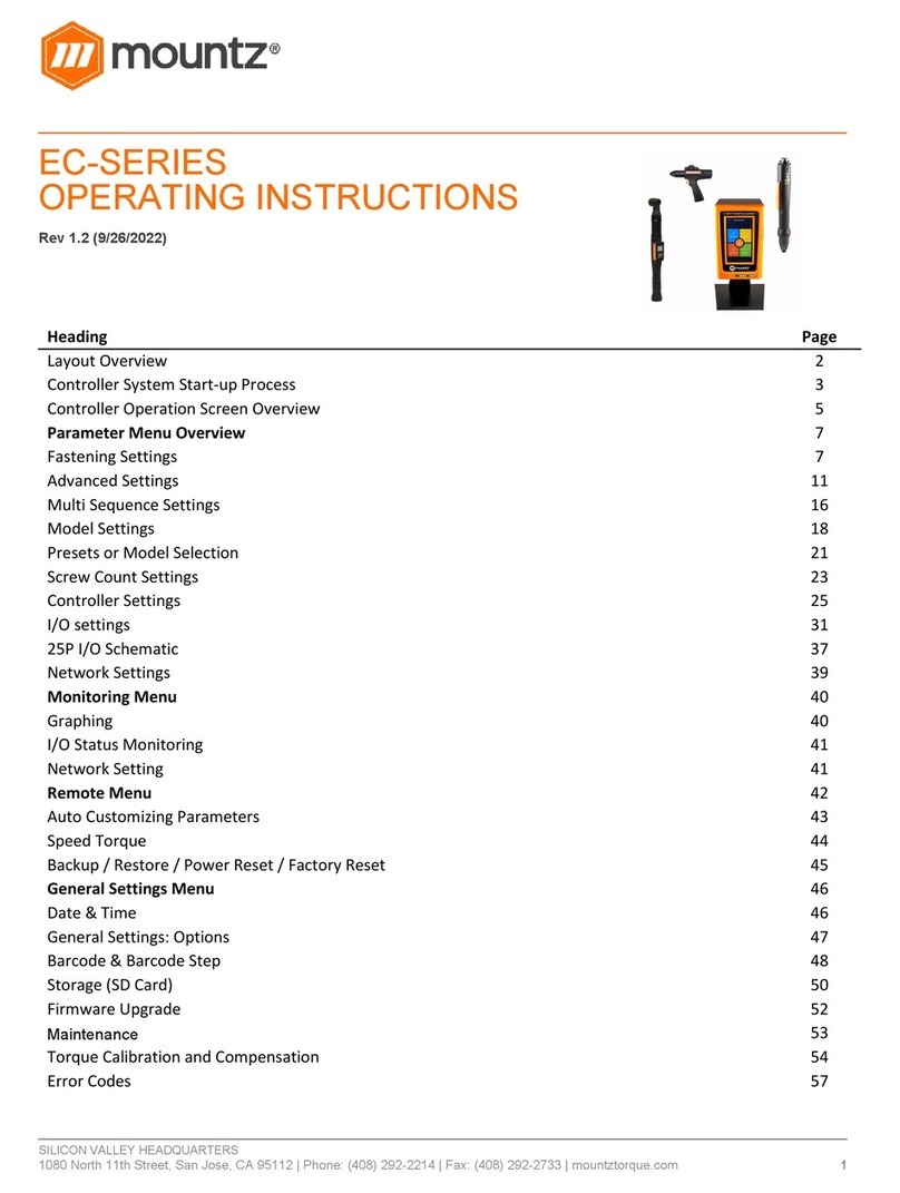
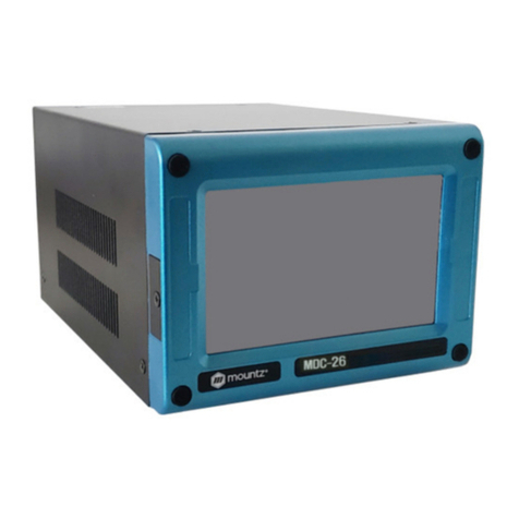
Mountz ECT Series User manual

SILICON VALLEY HEADQUARTERS
1080
North 11th Street, San Jose, CA 95112 | Phone: (408) 292
ECT-SERIES
OPERATING INSTRUCTIO
Rev 1.2 (9/26/2022)
Heading
Layout Overview
Controller System Start-up Process
Controller Operation Screen Overview
Parameter Menu Overview
Fastening Settings
Advanced Settings
Multi Sequence Settings
Model Settings
Presets or Model Selection
Screw Count Settings
Controller Settings
I/O settings
25P I/O Schematic
Network Settings
Monitoring Menu
Graphing
I/O Status Monitoring
Network Setting
Remote Menu
Auto Customizing Parameters
Speed Torque
Backup / Restore / Power Reset / Factory Reset
General Settings Menu
Date & Time
General Settings: Options
Barcode & Barcode Step
Storage (SD Card)
Firmware Upgrade
Maintenance
Torque Calibration and Compensation
Error Codes
North 11th Street, San Jose, CA 95112 | Phone: (408) 292
-2214 | Fax: (408) 292-2733 | mountztorque.com
OPERATING INSTRUCTIO
NS
Controller Operation Screen Overview
Backup / Restore / Power Reset / Factory Reset
Torque Calibration and Compensation
1
Page
2
3
5
7
7
11
16
18
21
23
25
31
37
39
40
40
41
41
42
43
44
45
46
46
47
48
50
52
53
54
57

SILICON VALLEY HEADQUARTERS
1080 North 11th Street, San Jose, CA 95112 | Phone: (408) 292-2214 | Fax: (408) 292-2733 | mountztorque.com
2
ECTD Controller
ECTD-5000U and ECTD-5000E controllers is compatible with ECT-Series smart electric
screwdrivers.
Input (Electric):
Input: AC120VC / AC230V, 50/60Hz 2.5A
Output (Electric): DC38V 3.5A
Fuse: 230V 25A
Operating Environment: 0 ~ 40℃ / 15 ~ 80% RH (without dew)
Front Panel: 4.3” Color LCD with touch screen
Communication: 1 x RS232C, 1 x Ethernet
Protocol: Modbus and Open Protocol
I/O: 8 Input & 8 Output flexible I/O (25P D-Sub)
No of Program Presets: 15
Error Display: Error code display ( 3 groups )
Dimension (W x L x H): 7 1/2” x 8” x 10 1/4”
ECT-Series Smart Electric Screwdrivers
DC38V, 5A max
Swiss DC servo motor
Built-in torque transducer and angle encoder
Built-in angle encoder
Power tool cable
Bottom View
RS232C 25 I/O Ethernet Upgrade
On/Off
Switch
Attach power
tool cable Plug in power
cord
In-Line Pistol Grip Right Angle Robotic

SILICON VALLEY HEADQUARTERS
1080 North 11th Street, San Jose, CA 95112 | Phone: (408) 292-2214 | Fax: (408) 292-2733 | mountztorque.com
3
Controller System Start-up Process
Before attempting to make any settings, it is essential to initialize the controller and electric screwdriver
as a set, as the information stored within the controller during testing at the time of manufacture may not
correlate with the screwdriver shipped with the system. This process should be used when first turning
on the unit or after changing an electric screwdriver.
Connect the screwdriver to the controller with the supplied cable
Connect the controller power cable
Power on the controller with a power switch
The controller screen will display an error message as below, and
the screwdriver is locked.
Note: Power off controller before disconnecting electric screwdriver
[E114]
Screwdriver recognition
error
Press
Controller
Press
Parameter

SILICON VALLEY HEADQUARTERS
1080 North 11th Street, San Jose, CA 95112 | Phone: (408) 292-2214 | Fax: (408) 292-2733 | mountztorque.com
4
Select screwdriver model in list
Power reset is done automatically and controller is initialized with selected screwdriver factory
parameters.
Torque unit selection:
If necessary change torque unit (changing torque unit will reset all parameters) same procedure as
above
Open driver
model list
Open torque
unit list
Select torque unit in the list

SILICON VALLEY HEADQUARTERS
1080 North 11th Street, San Jose, CA 95112 | Phone: (408) 292-2214 | Fax: (408) 292-2733 | mountztorque.com
5
Controller Operation Screen Overview
Operation screen is a default window when the controller power ON.
The real time monitoring data and target settings are displayed together.
To go other menu, click the menu icon on the top left side.
There are 4 menus the main menu and a Logout option
1. Parameter change 3. Remote
operation
2. Real time monitoring 4. Display settings.
Menu
Preset (Model) # 1 - 15
Monitoring Torque
Torque Target
Fastening Time
Count (Target / Count)
Fastening Result OK/NG/Ready
Date & Time
Monitoring Angle / Time
Angle A1 / A2
Speed Target / Monitoring
Torque Unit

SILICON VALLEY HEADQUARTERS
1080 North 11th Street, San Jose, CA 95112 | Phone: (408) 292-2214 | Fax: (408) 292-2733 | mountztorque.com
6
Touch Screen field to move
Real time monitoring
Main Menu
Preset # or Model select
Last count cancel

SILICON VALLEY HEADQUARTERS
1080 North 11th Street, San Jose, CA 95112 | Phone: (408) 292-2214 | Fax: (408) 292-2733 | mountztorque.com
7
Parameter Menu Overview
Fastening Settings
Parameters listed on A and B pages
for each Preset from 1 to 15

SILICON VALLEY HEADQUARTERS
1080 North 11th Street, San Jose, CA 95112 | Phone: (408) 292-2214 | Fax: (408) 292-2733 | mountztorque.com
8
Preset Selection
Type
Unit Range Initial
Description Control type
TC/AM: torque control / angle monitoring
AC/TM: angle control / torque monitoring
Target Torque
Unit Range Initial
set up in controller Tool range
Description TC/AM: Target torque
AC/TM: Max torque
Torque Limit
Unit Range Initial
Torque limit (TC) %
Min torque (AC)
%
Set up in controller
0 ~ 100
Tool range
0
Description TC/AM: torque monitoring tolerance +/- % of target for fastening Ok
AC/TM: Min torque
Snug Torque
Unit Range Initial
Set up in controller Tool range 0
Description In TC/AM: Point to start angle monitoring
In AC/TM: Point to control angle
Target Speed
Unit Range Initial
rpm Tool range Auto
Description Target speed: Speed is changed by torque setting automatically. To change
manually, Auto Speed must be Disabled in Controller

SILICON VALLEY HEADQUARTERS
1080 North 11th Street, San Jose, CA 95112 | Phone: (408) 292-2214 | Fax: (408) 292-2733 | mountztorque.com
9
Target Angle
Unit Range Initial
degree 0 ~ 9999 0
Description Target angle in AC/TM mode
Min Angle
Unit Range Initial
degree 0 ~ 9999 0
Description Minimum angle to be OK in TC/AM mode
Max Angle
Unit Range Initial
degree 0 ~ 9999 0
Description Maximum angle to be OK in TC/AM mode
Angle for Free Speed
Unit Range Initial
degree 0 ~ 9999 0
Description Angle for Free speed
Free Speed
Unit Range Initial
rpm Tool range 0
Description Manual setting speed. Shift back to the auto speed after the free angle
running

SILICON VALLEY HEADQUARTERS
1080 North 11th Street, San Jose, CA 95112 | Phone: (408) 292-2214 | Fax: (408) 292-2733 | mountztorque.com
10
Soft Start
Unit Range Initial
msec 0 ~ 300 0
Description Speed reach to the target in the setting time, Preset complement to
acceleration controller parameter
Seating Point Torque %
Unit Range Initial
% 10 ~ 95 50
Description In TC/AM: % of Target torque
Auto speed slow down to ramp-up speed for torque control
In AC/TM: to be set with same torque value as Snug torque, in % of Max
torque
Torque Rising Time
Unit Range Initial
msec 50 ~ 200 50
Description Time setting from seating point to the target
Ramp-up Speed
Unit Range Initial
rpm Tool range Auto
Description Speed after seating to the end of tightening
Torque Compensation
Unit Range Initial
% 80 ~ 120 100
Description Individual torque tuning on each preset, saved in the controller
The torque output can be adjusted in the selected preset ONLY, it does not
influence other presets.
For details, please refer to page 55

SILICON VALLEY HEADQUARTERS
1080 North 11th Street, San Jose, CA 95112 | Phone: (408) 292-2214 | Fax: (408) 292-2733 | mountztorque.com
11
Advanced Settings
Parameters listed on A and B pages
for each Preset from 1 to 15

SILICON VALLEY HEADQUARTERS
1080
North 11th Street, San Jose, CA 95112 | Phone: (408) 292
Advanced Functions:
In this mode there are 4 extra functions can be set
independently for each Preset.
1. Free Reverse Rotation
2. Engaging Torque Detection
3. Angle After Torque Up
4. Thread Tapping
Free Reverse Rotation (Before f
astening
The free reverse rotation guides the screw
hole smoothly with low speed.
Speed (rpm)
Unit
rpm
Description
Tool reverse rotation speed
Angle (turn)
Unit
0.1 turn
Description
Reverse rotation angle in rev
North 11th Street, San Jose, CA 95112 | Phone: (408) 292
-2214 | Fax: (408) 292-2733 | mountztorque.com
In this mode there are 4 extra functions can be set
astening
)
The free reverse rotation guides the screw
into the screw
Unit
Range
Initial
rpm
Tool range
Tool reverse rotation speed
Unit
Range
Initial
0.1 turn
0 ~ 20
Reverse rotation angle in rev
12
Initial
0
Initial
0

SILICON VALLEY HEADQUARTERS
1080 North 11th Street, San Jose, CA 95112 | Phone: (408) 292-2214 | Fax: (408) 292-2733 | mountztorque.com
13
Engaging Torque Detection
This setting is only possible when the screw engaging provides significantly higher torque than the
previous free run.
Speed
Unit Range Initial
rpm Tool range 0
Description Tool rotation speed
Torque (%)
Unit Range Initial
% 0 ~ 50 0
Description Engaging torque setting by percentage of target torque – detection will be
active from this value
Angle Limit (turn)
Unit Range Initial
0.1 turn 0 ~ 20 0
Description Max engaging rotation in rev
Time Limit (sec)
Unit Range Initial
sec 0 ~ 10 0
Description Max engaging time lap
Angle Start from Engaging
Unit Range Initial
YES - NO NO
Description If select, the monitoring angle count is reset and start again from engaging
torque detection point.

SILICON VALLEY HEADQUARTERS
1080 North 11th Street, San Jose, CA 95112 | Phone: (408) 292-2214 | Fax: (408) 292-2733 | mountztorque.com
14
Angle After Torque Up
After tightening by torque control, it manages extra angle control in both forward and reverse directions.
Speed
Unit Range Initial
rpm Tool range 0
Description Driver rotation speed
Angle
Unit Range Initial
degree 0 ~ 15000 0
Description Rotation angle
Direction
Unit Range Default
Forward - Reverse Forward
Description Angle rotation direction
Thread Tapping
This function is dedicated to through hole tapping with a torque pic during thread tapping.
TC/AM program will start once the tapping is done.
Typical thread tapping graph

SILICON VALLEY HEADQUARTERS
1080 North 11th Street, San Jose, CA 95112 | Phone: (408) 292-2214 | Fax: (408) 292-2733 | mountztorque.com
15
It is not the case in the chart (on prior page), but the tapping torque can be higher than the target torque
(tapping in metal sheets, for example)
Min Thread Torque
Unit Range Initial
set up in controller Tool range 0
Description Torque level to start tapping monitoring
Reach upward and higher than end torque parameter
Max Thread Torque
Unit Range Initial
set up in controller Tool range 0
Description Safety torque level - end preset with a specific alarm
Speed
Unit Range Initial
rpm Tool range 0
Description Driver rotation speed
Thread Tapping End Torque
Unit Range Initial
set up in controller Tool range 0
Description Torque level to end the thread tapping advance function
Reach downward and lower than min thread torque parameter
Angle Start from Engaging
Unit Range Initial
YES - NO NO
Description If select, the monitoring angle count is reset and start again from engaging
torque detection point.

SILICON VALLEY HEADQUARTERS
1080 North 11th Street, San Jose, CA 95112 | Phone: (408) 292-2214 | Fax: (408) 292-2733 | mountztorque.com
16
Multi Sequence Settings
Fastening Automation Workflows
When there is a repetitive series of tightening tasks, manufacturers should implement a fastening
automation workflow process. By creating a fastening automation workflow, the manufacturing process
becomes streamlined and reduces human error risk.
Group similar processes and assign a set of standardized tasks: program fastening sequences and
torque tolerances for each fastener in a sequence for sensitive and complex assembly joints. Workflow
automation is the best method to achieve tightening tasks efficiently. It produces reliable and accurate
torque control results.
Workflow automation provides visibility of the various fastening tasks and improves production efficiency,
consistency, and quality.
Multi sequence provides a cycle of fastening by a start signal.
Program maximum of 2 multi sequences.
Up to 20 steps per multi sequence program.
To program, select the command and required parameter on each step.
To finish the multi-sequence programming, last step command should be “END”.
For screw counting and I/O’s connections, please use the Models function.
Toggle up and down between
the number of steps

SILICON VALLEY HEADQUARTERS
1080 North 11th Street, San Jose, CA 95112 | Phone: (408) 292-2214 | Fax: (408) 292-2733 | mountztorque.com
17
Command Description Data (range)
NOP No operation No use
Fastening Tool start fastening process in forward rotation - Selected Preset
is fill in Data field
Preset selection 1 to 15
Loosening Tool start loosening process in reverse rotation Angle in 0.1 turn up to 999
Select preset# Select preset # (not mandatory ) Preset can be selected in data
of Fastening command.
Preset selection 1 to 15
Delay Time delay for setting time 1 to 999
Jump Move to the setting step 2 to 9
Count value = A Total number “A” to count 1 to 999
Sub if (A)
Subtract 1 from “A” and save the value replacing “A” . If the
value “ A” is not “0”, then move to the next lower step. If the
value “ A” is “0”, then move to 2nd lower step
No use
End Finish multi-sequence process (mandatory) No use
Be careful: Data can be set from 0 to 999. Please set correct value in fields.

SILICON VALLEY HEADQUARTERS
1080 North 11th Street, San Jose, CA 95112 | Phone: (408) 292-2214 | Fax: (408) 292-2733 | mountztorque.com
18
Model Settings
They are 15 sequencing models of 20 steps with assignable tightening
program batch counting and logical IO management.
Model should be activated in controller parameters.
The digital inputs for preset # select becomes model # select
automatically.
Each step can have one of the above commands with related setting
value.
There are 5 different type of command:
1. Input
2. Output
3. Fastening
4. Time Delay
5. Barcode Scan

SILICON VALLEY HEADQUARTERS
1080 North 11th Street, San Jose, CA 95112 | Phone: (408) 292-2214 | Fax: (408) 292-2733 | mountztorque.com
19
Fastening setting: The fastening with counting number follows all settings and features in Screw Count
menu except the number of screw.
The spindle can be locked automatically in all steps except Fastening step, by selecting Enable on the
menu Controller ‘Auto lock’ (model).
Input/Output setting: IO port used in models should be unassigned (None) in IO settings
Inputs port 9 to 15 are unassigned and dedicated to models
Command details
Command Description Data 1 Data 2
Input Mapping digital Input Input # select
from 1 - 8
0: No output NG
1: Active High
2: Active Low
3: High status
4: Low status
Output Mapping digital Output Output # select
from 1 - 8
0: No Output NG
1: On
2: Off
3: On for 0.5s and Off
4: On for 1.0s and Off
Fastening Start fastening
Preset #
from 1 – 13
14 : MA*
15 : MB*
Count number from 1 - 250
Delay Delay time - 1 to 250 (unit: 0.1s) 0.1 - 25 sec.
Bar code Require bar code scan None Barcode step data:
‘1 to 30’ registered barcode(step)
‘0’ any barcode scan
* To select preset 14 and 15, please program preset 14 and 15 in a one step multi-sequence.

SILICON VALLEY HEADQUARTERS
1080 North 11th Street, San Jose, CA 95112 | Phone: (408) 292-2214 | Fax: (408) 292-2733 | mountztorque.com
20
Bar code: receiving a barcode to go to next step
If model barcode step data is set between 1 to 30:
It can go next step by receiving only barcode data scanned in setting
menu Barcode (step)
If model barcode step data is set 0:
It can go next step by receiving any barcode data
Can be used to merged a part barcode with tightening results
This manual suits for next models
2
Table of contents
Other Mountz Controllers manuals
Popular Controllers manuals by other brands

Neptronic
Neptronic TUCB Series user guide

Crestron
Crestron DM-RMC-4K-100-C-1G quick start

ITEM
ITEM C Series manual

Emerson
Emerson digitax st series installation guide

elsner elektronik
elsner elektronik KNX S4-B10 230 V quick start guide

Roger Technology
Roger Technology AG CTRL Instruction and warnings for the installer