manuals.online logo
Brands
  1. Home
  2. •
  3. Brands
  4. •
  5. Reliance Foundry
  6. •
  7. Outdoor Light
  8. •
  9. Reliance Foundry R-7530 User manual

Reliance Foundry R-7530 User manual

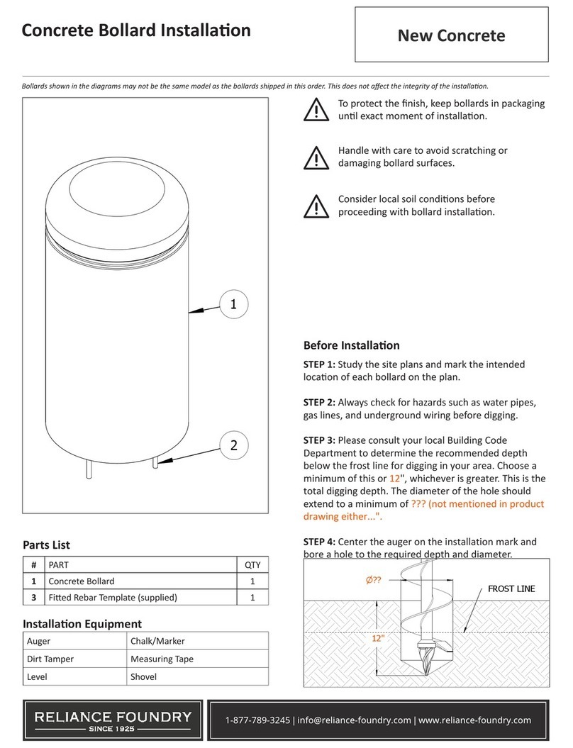
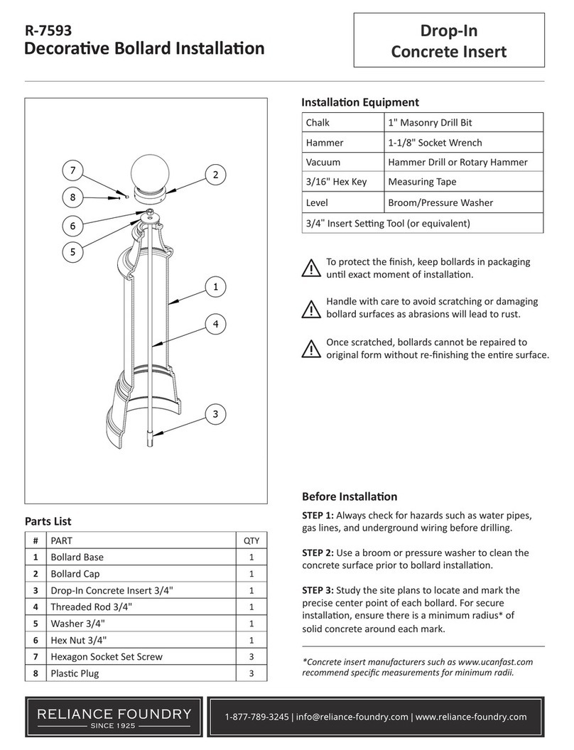
Decorave Bollard Installaon Adhesive Anchoring
1-877-789-3245 | info@reliance-foundry.com | www.reliance-foundry.com
To protect the nish, keep bollards in original
packaging unl exact moment of installaon.
Handle with care to avoid scratching or damaging
bollard surfaces as abrasions will lead to rust.
Once scratched, bollards cannot be repaired
to original form without re-nishing the enre
surface.
Parts List
Installaon Equipment
#PART QTY
1Bollard Base 1
2Bollard Cap 1
3Threaded Bar 1" 1
4Washer 1" 1
5Hex Nut 1" 1
6Hexagon Socket Set Screw 3
7Plasc Plug 3
1-1/8" Masonry Drill Bit Chalk
1-1/2" Wrench Caulking Gun
3/16" Hex Key Level
Hammer Drill or Rotary Hammer Measuring Tape
Adhesive Anchoring System* (included)
Before Installaon
STEP 1: Always check for hazards such as water pipes,
gas lines, and underground wiring before drilling.
STEP 2: Use a broom or pressure washer to clean the
concrete surface prior to bollard installaon.
STEP 3: Study the site plans to locate and mark the
precise center point of each bollard. For secure
installaon, ensure there is a minimum radius** of solid
concrete around each mark.
Drill the Hole
STEP 4: Tap a pilot divot hole in the center of each mark.
STEP 5: Set the depth control on the hammer drill (or
rotary hammer) to 4". If depth control is not available,
mark 4" on the masonry bit.
STEP 6: Drill a hole that has a 1-1/8" diameter and 4"
depth. Drill on high speed, using the hammer funcon
if available.
*Please refer to the adhesive manufacturer’s MSDS (included in
shipment) before using.
**Adhesive anchor manufacturers such as www.powers.com
recommend a minimum radius of 5".
R-7530
SECTION Y-Y
SCALE 0.48 : 1
PARTS LIST
DESCRIPTION
PART
NUMBER
QTY
ITEM
R7530 BaseR7530B
11
R7500
Threaded
Bar 1" x 38"
R7500B
AR 1"
1
4
Hex Nut 1" -
requires 1
1/2" wrench
Hex
Nut 1"
1
6
Hexagon
Socket Set
Screw 3/8" x
5/8" -
requires
3/16" hex key
Hexago
n
Socket
Set
Screw
3/8" x
5/8"
3
7
Polyethylene
Plug 3/8"
Polyethy
lene
Plug
3/8"
38
R7530 CapR7530C
1
2
Washer 1"
OD 2" Thick
1/8"
Washer
1" OD
2"
1
5
Polyethylene
Plug 7/8"
Polyethy
lene
Plug
7/8"
39
Y
Y
3
1
4
5
6
7
2
4"

1 1/8"
Decorave Bollard Installaon Adhesive Anchoring
1-877-789-3245 | info@reliance-foundry.com | www.reliance-foundry.com
4"
4"
PARTS LIST
DESCRIPTION
PART
NUMBER
QTY
ITEM
R7530 BaseR7530B
11
Drop-in
Concrete
Insert 3/4" -
requires 1" x
3 1/8" hole
(dia. x depth)
Drop-in
Concret
e Insert
3/4"
1
2
R7500
Threaded
Bar 3/4" x
30"
R7500B
AR 3/4"
1
4
R7530 CapR7530C
1
7
Hexagon
Socket Set
Screw 3/8" x
3/4" -
requires
3/16" hex key
Hexago
n
Socket
Set
Screw
3/8" x
3/4"
1
8
Polyethylene
Plug 3/8"
Polyethy
lene
Plug
3/8"
1
9
Install Plastic
Screw Cap
A
STEP 8
STEP 12 STEP 13
STEP 11
STEP 14
STEP 15
R-7530
Inspect the installaon. Abrasions should be
covered as soon as possible. For damage repair
or other servicing needs, please contact Reliance
Foundry’s sales department.
Secure the Bollard
STEP 7: Clear the hole of all debris and/or standing water
using the vacuum. Use a brush to remove any remaining
loose parcles.
STEP 8: Using the caulking gun, dispense the adhesive from
the boom up unl the hole is one-quarter full. Prevent air
pockets by withdrawing the mixing nozzle slowly.
STEP 9: Carefully place the bollard near the installaon
posion. When ready to install, remove its protecve
packaging.
STEP 10: Set the bollard base upright and maneuver it so
the center lines up with the drilled hole.
STEP 11: Lower the threaded rod through the top of the
bollard and into the drilled hole.
STEP 12: Insert the threaded rod the full 4" into the drilled
hole while turning for posive adhesion. The rod should
be centered in the bollard’s sha. Note: A minimum of 45
minutes at 68˚F is required for the anchoring system to set.
STEP 13: Place the washer over the threaded rod so it
rests on top of the bollard base. Apply the 1" nut to the
threaded rod and use a wrench to ghten unl the bollard
is secure.
STEP 14: Remove the bollard cap from packaging and place
on top of the sha of the bollard. Secure and align the
bollard cap to the bollard base with the three set screws.
Tighten in equal amounts to ensure the cap remains
centered.
STEP 15: Place the plasc plugs (A) over the heads of the
set screws.

Other Reliance Foundry Outdoor Light manuals

Reliance Foundry R-7835 User manual

Reliance Foundry

Reliance Foundry R-7835 User manual

Reliance Foundry R-7535 User manual

Reliance Foundry

Reliance Foundry R-7535 User manual

Reliance Foundry R-8464 User manual

Reliance Foundry

Reliance Foundry R-8464 User manual
Reliance Foundry R-7539 User manual

Reliance Foundry

Reliance Foundry R-7539 User manual

Reliance Foundry R-7593 User manual

Reliance Foundry

Reliance Foundry R-7593 User manual

Reliance Foundry Concrete Bollard User manual

Reliance Foundry

Reliance Foundry Concrete Bollard User manual

Reliance Foundry R-7593 User manual

Reliance Foundry

Reliance Foundry R-7593 User manual

Reliance Foundry R-7593 User manual

Reliance Foundry

Reliance Foundry R-7593 User manual

Reliance Foundry R-8471 User manual

Reliance Foundry

Reliance Foundry R-8471 User manual

Popular Outdoor Light manuals by other brands

Kichler Lighting HELEN 37536 instructions

Kichler Lighting

Kichler Lighting HELEN 37536 instructions

Thorn OXANE L installation instructions

Thorn

Thorn OXANE L installation instructions

esotec Solar Globe Light multicolor 20 operating instructions

esotec

esotec Solar Globe Light multicolor 20 operating instructions

mitzi HL200201 ELLIS Assembly and mounting instructions

mitzi

mitzi HL200201 ELLIS Assembly and mounting instructions

HEPER TILA S AFX 3 Module Installation & maintenance instructions

HEPER

HEPER TILA S AFX 3 Module Installation & maintenance instructions

Designplan TRON 180 installation instructions

Designplan

Designplan TRON 180 installation instructions

Sealey LED37 instructions

Sealey

Sealey LED37 instructions

nordlux VEJERS Mounting instruction

nordlux

nordlux VEJERS Mounting instruction

SImx ELITE LED LHTC637 installation instructions

SImx

SImx ELITE LED LHTC637 installation instructions

GEV CAROLINE 10833 manual

GEV

GEV CAROLINE 10833 manual

WE-EF PFL540 LED Installation and maintenance instructions

WE-EF

WE-EF PFL540 LED Installation and maintenance instructions

HEPER DOGO Side LW6048.585-US Installation & maintenance instructions

HEPER

HEPER DOGO Side LW6048.585-US Installation & maintenance instructions

BEGA 84 253 Installation and technical information

BEGA

BEGA 84 253 Installation and technical information

HEPER LW8034.003-US Installation & maintenance instructions

HEPER

HEPER LW8034.003-US Installation & maintenance instructions

HEPER MINIMO Installation & maintenance instructions

HEPER

HEPER MINIMO Installation & maintenance instructions

LIGMAN BAMBOO 3 installation manual

LIGMAN

LIGMAN BAMBOO 3 installation manual

Maretti TUBE CUBE WALL 14.4998.04 quick start guide

Maretti

Maretti TUBE CUBE WALL 14.4998.04 quick start guide

Maxim Lighting Carriage House VX 40428WGOB installation instructions

Maxim Lighting

Maxim Lighting Carriage House VX 40428WGOB installation instructions

manuals.online logo
manuals.online logoBrands
  • About & Mission
  • Contact us
  • Privacy Policy
  • Terms and Conditions

Copyright 2025 Manuals.Online. All Rights Reserved.