manuals.online logo
Brands
  1. Home
  2. •
  3. Brands
  4. •
  5. Reliance Foundry
  6. •
  7. Outdoor Light
  8. •
  9. Reliance Foundry R-8464 User manual

Reliance Foundry R-8464 User manual

Parts List
Installaon Equipment
#PART QTY
1Removable Bollard 1
2Receiver 1
3Receiver Cover 1
4Key 2
5Reecve Tape (oponal) 1
Auger Chalk/Marker
Dirt Tamper Level
Measuring Tape
1-877-789-3245 | info@reliance-foundry.com | www.reliance-foundry.com
Removable Bollard Installaon
R-8464
Removable Bollard
To protect the nish, keep bollards in original
packaging unl exact moment of installaon.
Handle with care to avoid scratching or
damaging bollard surfaces.
Once scratched, bollards cannot be repaired
to original form without re-nishing the enre
surface.
Consider local soil condions before proceeding
with bollard installaon.
Before Installaon
STEP 1: Study the site plans and mark the intended
locaon of each bollard on the plan.
STEP 2: Always check for hazards such as water pipes,
gas lines, and underground wiring before digging.
STEP 3: Please consult your local Building Code
Department to determine the recommended depth
below the frost line for digging in your area. Choose a
minimum of this or 6-3/4", whichever is greater. Then
add a minimum of 6" for holding the drain rock.* This is
the total depth. The diameter of the hole should extend
to a minimum of 12".
* Recommended depth for drain rock is a minimum of 6". Depth
will also depend on local soil condions, weather condions, and
engineering requirements.
PARTS LIST
DESCRIPTION
PART
NUMBER
QTY
ITEM
R8464
Removable
Bollard
Assembly
R8464
11
R8464R
Removable
Bollard
Receiver
R8464R
1
2
R8464RC
Removable
Bollard
Receiver
Cover
R8464R
C
1
3
Optional
Reflective
Tape, Max.
1-1/8" Width
Reflectiv
e Tape
(Option
al)
14
1
2
3
5
4
6 3/4" min
6" min
12" min
R-8464
1-877-789-3245 | info@reliance-foundry.com | www.reliance-foundry.com
Removable Bollard Installaon
R-8464
Removable Bollard
STEP 4: Center an auger on the installaon mark and bore
a hole to the required measurements.
STEP 5: Ensure the area is properly formed to create a
perimeter that will hold wet concrete. Use a dirt tamper**
to compact the soil below the intended surface.
STEP 6: Prepare the bollard and receiver for designated
locaon. Keep the bollard in its protecve packaging. Add
the drain rock to the excavaon site, keeping in mind that
the receiver will be installed so that the top edge of the
receiver is slightly above surface grade. A slight berm is
recommended to help with water drainage.
Prepare the Concrete
STEP 7: Ensure that the proper rao of water and concrete
mix is used. The concrete should have a similar texture to
moldable clay.
STEP 8: Place the receiver in the designated locaon and
ensure that the top edge of the receiver is slightly above
surface grade. Note: If necessary, try dry ng the bollard
(with packaging sll on) into the receiver and use a level to
ensure it is plumb before proceeding with pouring concrete.
STEP 9: Be sure to orient the receiver in such a way
that the keyhole will point in the desired direcon. It is
recommended that the orientaon of all receivers be the
same.
Pour the Concrete
Before pouring the concrete, determine if your local frost
line is less than or greater than 6-3/4". When pouring
concrete, be sure to pour it evenly. The concrete should also
be slightly raised up towards the top edge of the receiver
plate to create a slight berm.
STEP 10 (A): If the local frost line is less than 6-3/4", simply
pour the concrete into the site.
STEP 10 (B): If the local frost line is greater than 6-3/4",
pour the concrete into the site and then provide adequate
drainage by piping through the concrete and connecng to
the drain rock layer underneath.
**Dirt tamping is not required if working on undisturbed soil.
STEP 6
STEP 4
STEP 9
STEP 10 (A)
R-8464
SECTION D-D
SCALE 1
D
D
STEP 10 (B)
1-877-789-3245 | info@reliance-foundry.com | www.reliance-foundry.com
Removable Bollard Installaon
R-8464
Removable Bollard
Inspect the installaon. Abrasions should be
covered as soon as possible. For damage repair
or other servicing needs, please contact Reliance
Foundry’s sales department.
STEP 11: Allow the concrete to cure for a minimum of
2–3 days. Note: Moisture in the environment and cool
temperatures can signicantly slow the process.
Secure the Bollard
STEP 12: Keep the bollard in its protecve packaging. Aer
ensuring the concrete surface has fully cured, carefully
place the bollard near the installaon site.
STEP 13: When ready to install, remove the bollard’s
protecve packaging.
STEP 14: Remove the receiver cover and turn the key in
order to retract the plunger and lower the bollard into the
receiver.
STEP 15: Aer seng the bollard in the receiver, li and
hold it while releasing and removing the key.
STEP 14
R-8464
STEP 15

Other Reliance Foundry Outdoor Light manuals

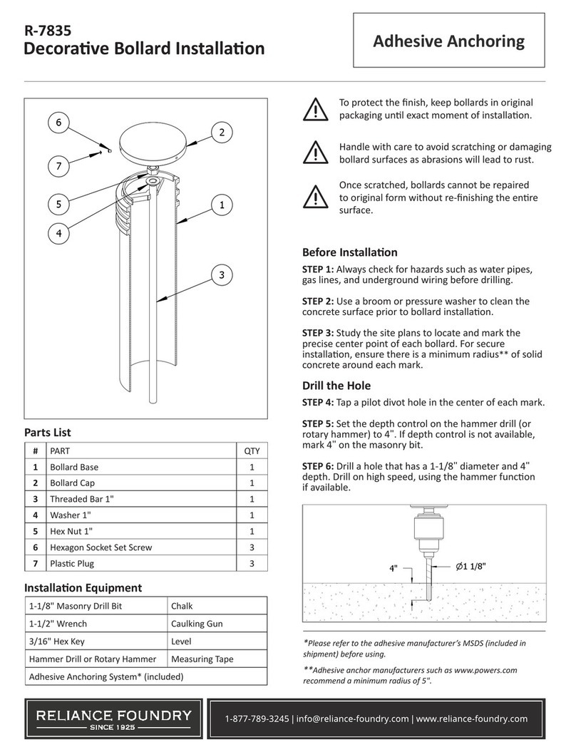
Reliance Foundry R-7835 User manual

Reliance Foundry

Reliance Foundry R-7835 User manual

Reliance Foundry R-7593 User manual

Reliance Foundry

Reliance Foundry R-7593 User manual

Reliance Foundry R-7530 User manual

Reliance Foundry

Reliance Foundry R-7530 User manual

Reliance Foundry R-8471 User manual

Reliance Foundry

Reliance Foundry R-8471 User manual
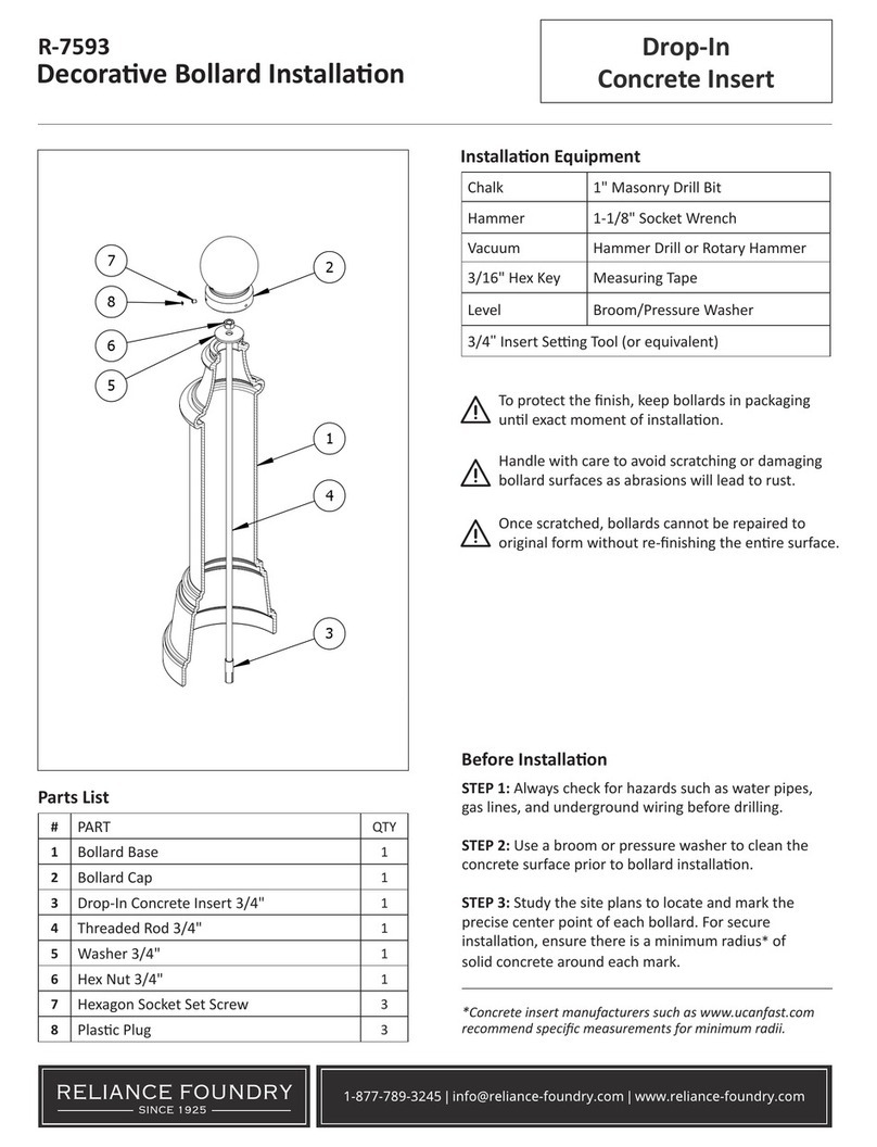
Reliance Foundry R-7539 User manual

Reliance Foundry

Reliance Foundry R-7539 User manual

Reliance Foundry R-7593 User manual

Reliance Foundry

Reliance Foundry R-7593 User manual
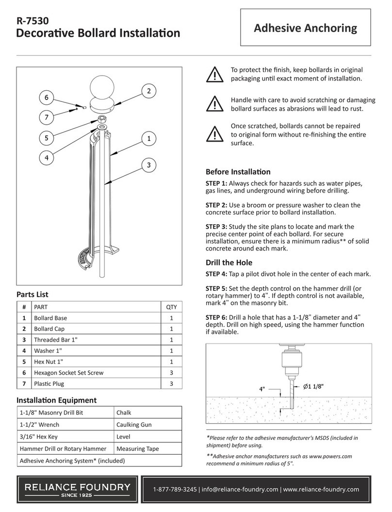
Reliance Foundry R-7593 User manual

Reliance Foundry

Reliance Foundry R-7593 User manual

Reliance Foundry R-7535 User manual

Reliance Foundry

Reliance Foundry R-7535 User manual

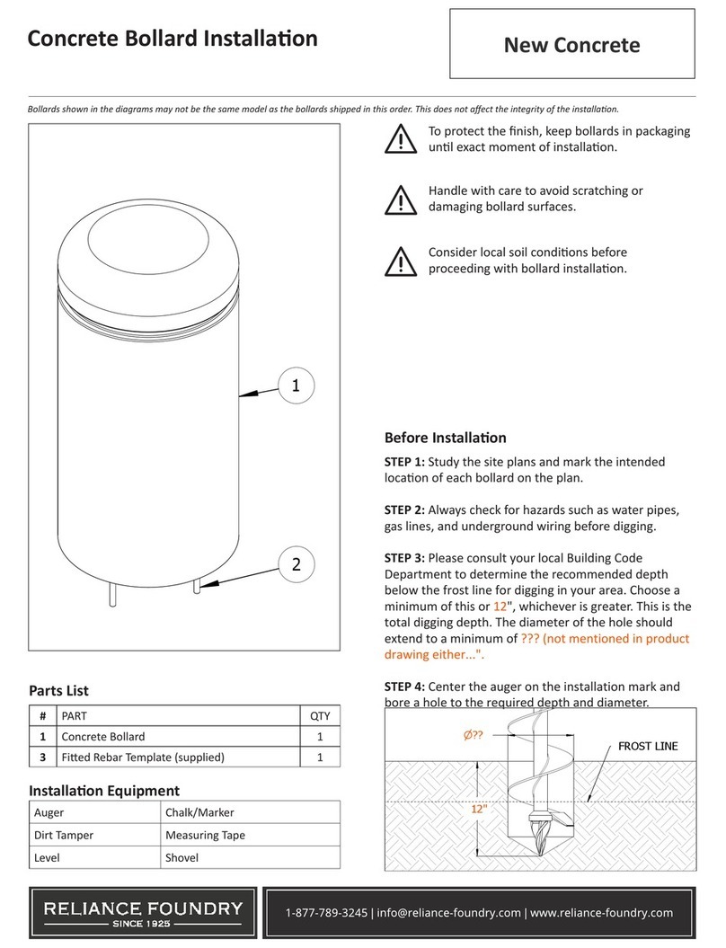
Reliance Foundry Concrete Bollard User manual

Reliance Foundry

Reliance Foundry Concrete Bollard User manual

Popular Outdoor Light manuals by other brands

OVE ALICE COACH 15LCO-ALIC12-ALUXI installation manual

OVE

OVE ALICE COACH 15LCO-ALIC12-ALUXI installation manual

BOSS ILLUMINATION VIO product manual

BOSS ILLUMINATION

BOSS ILLUMINATION VIO product manual

Sunnydaze Decor INA-900 manual

Sunnydaze Decor

Sunnydaze Decor INA-900 manual

Würth WLH 1 Premium Translation of the original operating instructions

Würth

Würth WLH 1 Premium Translation of the original operating instructions

SLV Elektronik ROX ACRYL POLE Series operating manual

SLV Elektronik

SLV Elektronik ROX ACRYL POLE Series operating manual

MOOD CHIC instruction manual

MOOD

MOOD CHIC instruction manual

Trilux Symbol I 450 Series Mounting instructions

Trilux

Trilux Symbol I 450 Series Mounting instructions

Philips 163558716 user manual

Philips

Philips 163558716 user manual

YATO YT-81775 Original instructions

YATO

YATO YT-81775 Original instructions

esotec 102090 manual

esotec

esotec 102090 manual

Satco NUVO LIGHTING 65-064 Installation and service instructions

Satco

Satco NUVO LIGHTING 65-064 Installation and service instructions

Quoizel MOI8408EK installation guide

Quoizel

Quoizel MOI8408EK installation guide

Altman SS UV Series installation manual

Altman

Altman SS UV Series installation manual

GREENLUX Shoebox 02 installation manual

GREENLUX

GREENLUX Shoebox 02 installation manual

Buffalo CC036 instruction manual

Buffalo

Buffalo CC036 instruction manual

Unilamp VAREE instruction manual

Unilamp

Unilamp VAREE instruction manual

Winter Wonder Lane XL3211205 Operation and safety instructions

Winter Wonder Lane

Winter Wonder Lane XL3211205 Operation and safety instructions

LIGMAN HA-60197-S installation manual

LIGMAN

LIGMAN HA-60197-S installation manual

manuals.online logo
manuals.online logoBrands
  • About & Mission
  • Contact us
  • Privacy Policy
  • Terms and Conditions

Copyright 2025 Manuals.Online. All Rights Reserved.