Remco PROFLO 3300 Quick start guide

763-253-4740 | www.remcoindustries.com | ProFlo Owner’s Manual | REMCO INDUSTRIES 1
Operational and Installation
Guidelines, Repair & Parts
The Standard For
Professional Grade
Diaphragm Pumps.
ProFlo™ 3300 | 5500 | FatBoy®
Contents
Operational and Installation Guidelines .................................2
Installation Procedure...............................................3
Troubleshooting Guidelines ..........................................3
Servicing.........................................................3
ProFlo™3300 Series Performance/Heat Rise Charts.......................4
ProFlo™5500 Series Performance/Heat Rise Charts.......................4
ProFlo™FatBoy Series Performance/Heat Rise Charts .....................4
Repalcement parts ProFlo™3300......................................5
Repalcement parts ProFlo™5500......................................6
Repalcement parts ProFlo™FatBoy ....................................7
Standard Warranty .................................................8
3300
5500
Fatboy

2REMCO INDUSTRIES | ProFlo Owner’s Manual | www.remcoindustries.com | 763-253-4740 763-253-4740 | www.remcoindustries.com | ProFlo Owner’s Manual | REMCO INDUSTRIES 3
Please read these Operational and Installation Guidelines before
installing the ProFlo™ Series Pumps. If additional help is needed,
please consult the Factory.
CAUTIONS
• Waterpipeconnectionsandxturesdirectlyconnectedtoa
potable water supply shall be sized, installed and maintained
in accordance with Federal, State, and local codes.
• Donotoperatethepumpabovethepressurelimitations
speciedonthedatalabel.
• Neveroperatethepumpinaharshenvironmentorhazardous
atmosphere, since motor brush and switch may cause
electrical arcing.
• Do not pump gasoline or other flammable liquids.
Pump head materials are designed for use with water
only. Do not use with petroleum products.
• Do not assume fluid compatibility. If the fluid is
improperly matched to the pumps’ elastomers,
a leak may occur
• Aslongasthereisinletwaterpressure,thepumpwillnotstop
forward flow of water even if the motor is turned off. Be sure
the system has positive means of shutting off water supply.
• Alwaysconsiderelectricalshockhazardwhenworkingwith
and handling electrical equipment. If uncertain, consult
an Electrician. Electrical wiring should only be done by a
qualiedElectricianperLocalandStateElectricalCodes.
MOUNTING
• Thepumpshouldbemountedinadryplaceandaway
from any source of heat. If an enclosure is used, special
instructions for cooling the motor may be necessary. Consult
the Factory.
• Donotsubjectthepumptoextremehighorlow(freezing)
temperatureswhileinoperation.(Operatingambient
temperaturerangeis32ºFto115ºF).
• Thepumpmaybemountedhorizontallywiththeoutletport
on the right when viewed from the pump end or with the
pump above the mount; or vertically with the pump above
or below the motor.
PLUMBING
• Thepumpisequippedwitheitherapressuresensing
demand switch, a bypass relief valve, or both which controls
themaximumsafeoperatingpressure.
• Werecommenduseofexibletubingwithproper
pressure rating.
• Pumpwillprimeonlyifallpressureisrelievedfromoutletport.
• Itisrecommendedthatdebris-freewaterbepumpedoran
in-linesedimentlter(100mesh)beinstalledattheinletside
tokeepforeigndebrisoutofthesystem.
• Thepumpshouldalwaysbemountedpriortoany
components which could introduce particles to the water;
thus, preventing them from entering the pump chambers and
possibly causing clogging.
• Avoidanysharpbendswhichmaycrimptubingandrestrict
ow.Use90ºelbowttingsifnecessary.REMCOprovides
pumpswithdifferentkindsofttings.PleaseconsultFactory
for your needs.
ELECTRICAL
• TheProFlo™SeriesPumpsaredesignedforintermittentduty,
but may run continuously if the motor temperature does not
exceedtherecommendedlimit.SomeProFlo™SeriesPumps
are equipped with thermally protected motors and in case
motortemperatureexceedsthermalcut-outrating,pump
will shut down and will not restart until motor cools down to
speciedtemperature.PleaseconsulttheappropriateData
Sheet for continuous running parameters, noting the effect
ofrapidOn/OffCycling(paragraph9,page2).
• Ifapowersupplyisusedwiththesystemandthesupply
is not furnished by REMCO, it will need to be reviewed for
correct application and approval by REMCO.
Operational and Installation Guidelines
Please read this Owner’s Manual completely before using this
pump.Assemble,test,anduseonlyinaccordancewiththe
Owner’s Manual instructions.
READandFOLLOWchemicalsafetyinstructions.Pesticides
are hazardous chemicals.
KNOW emergency procedures BEFORE handling chemicals.
Pumpleaks,bodilychemicalcontact,poisoning,andspills
require immediate response.
AVOIDinhaling,ingesting,orcomingintocontactwithany
chemicals.
WEARpersonalprotectivegearwhenoperating,cleaning,and
servicing the pump.
KEEP pump and spray materials away from children and pets.
Pesticidesareespeciallytoxictothem.
DO NOT TURN ON POWER to pump until ready to spray
in order to avoid unintentional spray release.
Improper use of the pump or handling of chemicals could result
inseriousinjuryorillnesstotheoperatorornearbypersons/
animals, or could cause damage to the environment.
Operational and Installation Warnings
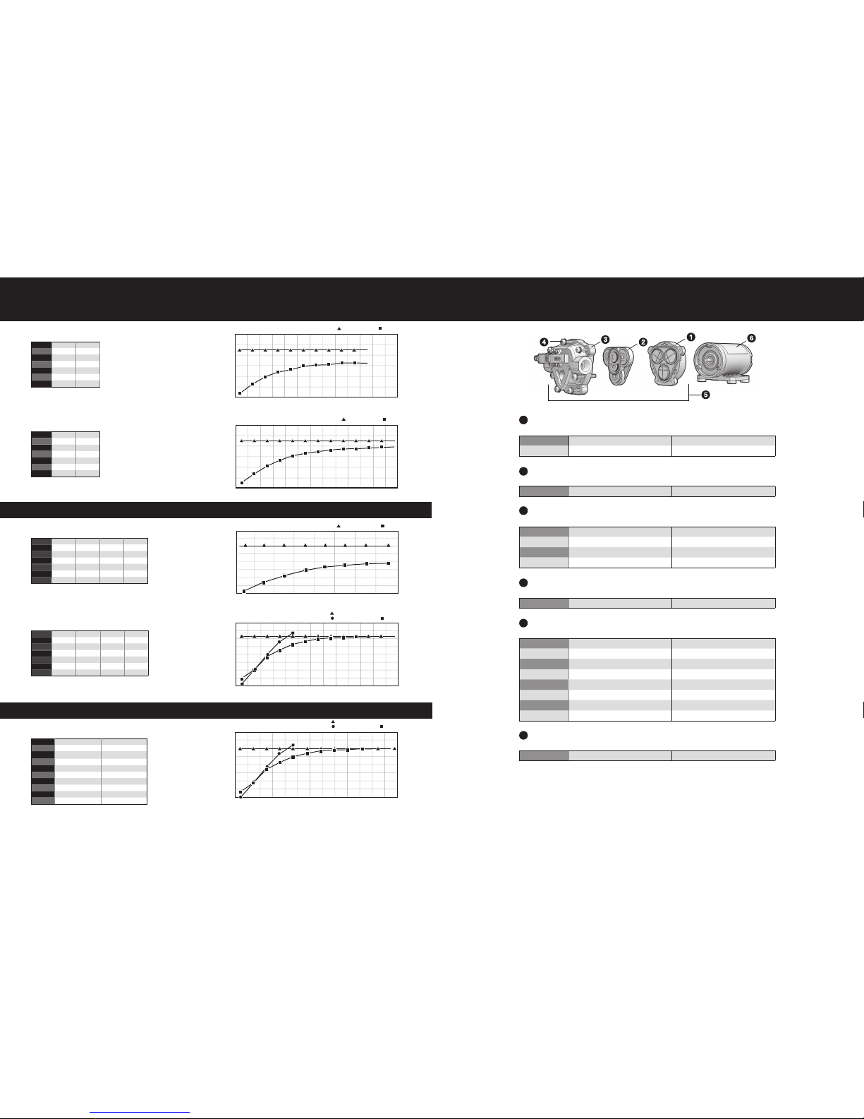
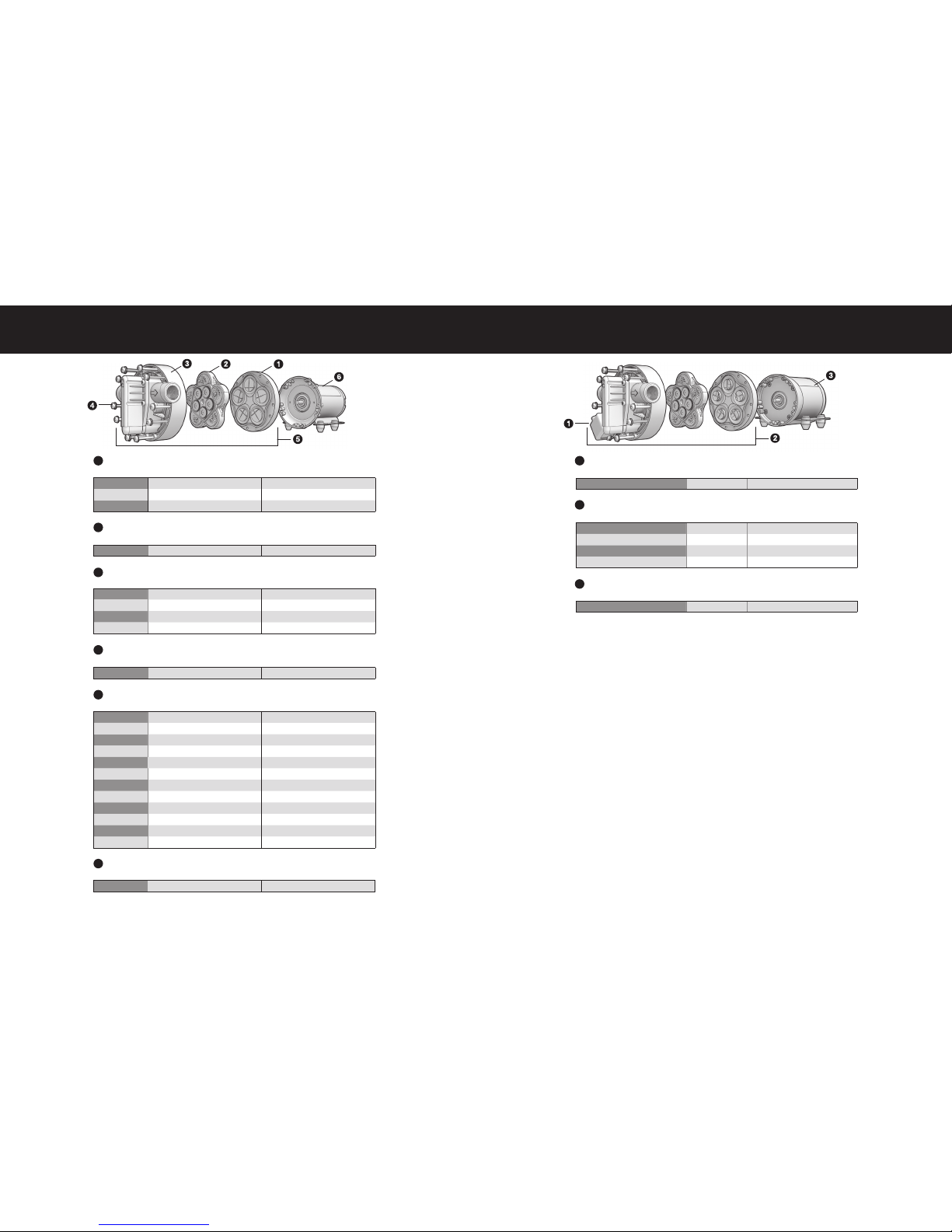
ProFlo™ 3300 | 5500 | FatBoy®ProFlo™ 3300 | 5500 | FatBoy®
NOTE
This pump is recommended for use in spraying non-flammable liquids such as pesticides, water for plants/trees or dust control, ice
controlchemicals,orwater-basednon-ammablesealantsorstainsforoutdoorwoodsurfaces.However,WERECOMMENDTHAT
THEPUMPSNOTBEUSEDFOROTHERPURPOSESONCEITHASBEENUSEDFORSPRAYINGPESTICIDES.
Anychemicalwillleavesomeresidualinthepump,evenafterthepumphasbeenproperlycleaned.Theseresidualchemicalscan
haveunexpectedeffectsonfutureuses.Forexample,sprayingwaterorotherliquidsthatarecontaminatedwithresidualpesticide
may result in unforeseen hazards to plant or animal life.
Troubleshooting Guidelines
IF PUMP WILL NOT START CHECK
• Correctvoltage(±10%)andelectricalconnections
• Fuseorbreaker
• Pressureswitchoperationandcorrectvoltageatswitch
• Rectierormotorforopenorgroundedcircuit
• Lockeddriveassembly.
IF PUMP WILL NOT PRIME (NO DISCHARGE WITH
MOTOR RUNNING) CHECK
• Debrisinstrainer
• Restriction(kinks)ininlet/outlettubes
• Debrisorswellingininlet/outletvalves
• Airleakinginfrominlet
IF PUMP WILL NOT SHUT OFF (OUTPUT LINE CLOSED
AND NO LEADS) CHECK
• Airtrappedinoutletlineorpumphead
• Correctvoltagetopump
• Debrisinpumpinlet/outletvalves
• Loosedriveassemblyorpumpheadscrews
• Pressureswitchoperations/adjustments
• Leaks
IF PUMP LEAKS FROM PUMP HEAD
OR SWITCH CHECK:
• Loosescrewsatswitchorpumphead
• Switchdiaphragmrupturedorpinched
• Punctureddiaphragmifuidispresent
The basic demand pump is controlled by a built-in pressure
sensing demand switch. When a faucet or valve is opened
down stream of the pump, line pressure drops, thus starting
the pump automatically. Conversely, when the valve shuts,
the line pressure increases turning the pump off automatically.
The pressure switch actuates in response to the pump outlet
pressure at a predetermined and preset pressure. The pump
label indicates the pre-set OFF pressures. Typically, the OFF
pressureisaccuratelysetattheFACTORYandtheONpressure
is within an allowable range below that value. In response to
the characteristics of the system in which the pump is installed,
suchastheexibilityandlengthofthetubing,andthefaucet
or valves and the duration that they are open, these pressure
settings may vary. Therefore, change in pressure settings is
expectedwithuseandovertime.
If the pump does not have an integral pressure sensing demand
switch(i.e.pumpisoperatedwithanexternalcontrol),pumpwill
beequippedwithabypassreliefvalve(bypassisfactorypreset).
Read the OPERATIONAL AND INSTALLATION GUIDELINES
on the other side carefully before starting to install the
pump. Consult the Factory if there is any question.
Determine the optimum location for your pump before
proceeding.
• Turnofftheuidsupply.
• Cuttheexibletubinginsufcientlengthtoavoidanystress
on the tubing or hose where it connects to the pump or the
ttingonanyaccessoryorhose.
• Inserttubingorhoseintopumpports.Ifcompressionttings
with threaded nuts are used, insert tubing until it bottoms out
in the port and hand tighten the compression nut until the
connection is tight. Then use a wrench to tighten the nut 1/2
turnclockwiseorfollowthewrenchtighteninginstructions
providedbythettingmanufacturer.
• TheProFlo™Series pump is now ready for operation. Open
the inlet valve if any to allow fluid to flow to the pump.
• Ifthepowersourceisatransformer,plugtheappropriate
REMCO supplied or approved transformer into the receptacle
and connect the pump to the transformer. If the power source
is not a transformer, connect the pump to the appropriate
powersource.Openthedischargeordispensingvalve.Allow
water to circulate, purging any entrapped air.
• Thepumpwillnowstartbuildingpressure.Operating
pressure will vary with flow rate, flow valve, feed-water
pressureandlinevoltage.Checkforttingleaks.
• Ifcompressionttingswiththreadednutsareused,observe
anyleaksafterpumphasrunforapproximately15minutes.
Furthertightencompressionnutsapproximately1/8to1/4of
aturnonallttingsinthesystem.Wait15minutesandrepeat
theleakcheck.
NOTE: Further adjustments should not be necessary
although it may take several days of operation before
all the air has been purged and the system is stabilized.
• RapidOn/OffCyclingmustbelimitedtonomorethan6times
per minute, even if the pump is operating in the Continuous
Duty zone. Cycling could cause the motor to heat beyond
therecommendedmaximumtemperature,andreducethe
operational life of the pump and pressure-sensing switch.
Installation Procedure
Servicing
EVERY YEAR
Checksystemagainstoperatingstandards.Ifcontinuousduty,replacelowerhousingassembly
EVERY OTHER YEAR
Checkagainstoperatingstandards.Ifcontinuousduty,replacemotor
EVERY FIFTH YEAR
Replace valves

4REMCO INDUSTRIES | ProFlo Owner’s Manual | www.remcoindustries.com | 763-253-4740 763-253-4740 | www.remcoindustries.com | ProFlo Owner’s Manual | REMCO INDUSTRIES 5
Performance 3301 & 3321
Performance 3303 & 3323
PSI GPM Amps
OPEN 1.20 3.50
10 1.10 4.25
20 1.05 4.50
30 1.00 5.00
40 .95 5.25
50 0.9 5.50
60 0.8 5.50
PSI GPM Amps
OPEN 2.00 3.50
10 1.70 4.50
20 1.60 5.00
30 1.45 5.50
40 1.40 6.00
50 1.35 7.00
60 1.25 7.50
Performance 5534 & 5535
PSI GPM Amps GPM Amps
OPEN 3.10 4.00 3.50 4.50
10 2.80 5.00 2.85 5.50
20 2.30 6.00 2.45 6.50
30 2.10 7.00 2.15 7.50
40 1.90 8.00 1.95 8.50
50 1.65 8.50 1.75 9.00
60 1.45 9.50 1.55 10.00
PSI GPM Amps GPM Amps
OPEN 4.55 7.50 5.11 8.00
10 4.10 8.50 4.75 9.50
20 3.75 9.50 4.30 11.00
30 3.40 11.00 3.85 13.00
40 3.05 12.50 3.40 15.00
50 2.75 14.00 3.00 17.00
60 2.45 15.50 2.55 18.00
Performance 5536 & 5537
PSI GPM Amps
10 7.00 11.00
20 6.81 12.00
30 6.45 12.00
40 5.96 13.00
50 5.50 15.00
60 4.98 17.00
70 4.41 19.00
80 3.96 21.00
90 3.52 23.00
100 2.55 25.00
Performance Fatboy
ProFlo™ 3300 Series | Replacment Parts
Part Number GPM Description
UHA-7880-7F77 1 GPM / 2 GPM THREADED W/ PRESSURE SWITCH
UHA-7880-8I77 1 GPM / 2 GPM THREADED W/ BYPASS
UHA-7863-7F77 1 GPM / 2 GPM QUICK ATTACH W/ PRESSURE SWITCH
UHA-7863-8I77 1 GPM / 2 GPM QUICK ATTACH W/ BYPASS
Part Number GPM Description
LHA-7860-7F77 1 GPM DEMAND OR BYPASS
LHA-7863-7F77 2 GPM DEMAND OR BYPASS
Part Number GPM Description
7880-7F77 1 GPM THREADED W/ PRESSURE SWITCH
7880-8I77 1 GPM THREADED W/ ADJUSTABLE BYPASS
7883-7F77 2 GPM THREADED W/ PRESSURE SWITCH
7883-8I77 2 GPM THREADED W/ ADJUSTABLE BYPASS
7860-7F77 1 GPM QUICK ATTACH W/ PRESSURE SWITCH
7860-8I77 1 GPM QUICK ATTACH W/ ADJUSTABLE BYPASS
7863-7F77 2 GPM QUICK ATTACH W/ PRESSURE SWITCH
7863-8I77 2 GPM QUICK ATTACH W/ ADJUSTABLE BYPASS
Part Number GPM Description
M382-S 1 GPM / 2 GPM W/2 PIN CONNECTOR, NO ON/OFF SWITCH
Part Number GPM Description
11-158-100 1 GPM / 2 GPM 4 MOUNTING BOLTS W/ WASHERS
Part Number GPM Description
VHA-7863-7F77 1 GPM / 2 GPM DEMAND OR BYPASS
Upper Housing Assembly
Lower Housing Assembly
Complete Pump Head Assembly
12 VDC Motor
Mounting Bolt Kit
Valve Housing Assembly
1
2
3
4
5
6
Heat Rise 5534 & 5535
MOTOR SHELL (TEMPERATURE)
0 10 20 30 40 50 60 70
220
200
180
160
140
120
100
80
60
TIME (MINUTES)
Maximum Motor Temp 10 Amps
TIME (MINUTES)
0 10 20 30 40 50 60 70 80 90 100 110 120
Heat Rise 5536 & 5537
MOTOR SHELL (TEMPERATURE)
220
200
180
160
140
120
100
80
60
Maximum Motor Temp
Maximum Current 18 Amps 14 Amps
Maximum Motor Temp
Heat Rise Fatboy
MOTOR SHELL (TEMPERATURE °F)
0 10 20 30 40 50 60 70 80 90 100 110 120
220
200
180
160
140
120
100
80
60
TIME (MINUTES)
Maximum Current 30 Amps 25 Amps
ProFlo™ 5500 Series | Performance & Heat Rise
ProFlo™ FatBoy® | Performance & Heat Rise
ProFlo™ 3300 Series | Performance & Heat Rise
Heat Rise 3323/3303
MOTOR SHELL (TEMPERATURE °F)
0 10 20 30 40 50 60 70 80 90 100 110 120
180
160
140
120
100
80
60
TIME (MINUTES)
Maximum Motor Temp 8 Amps
Heat Rise 3321/3301
MOTOR SHELL (TEMPERATURE °F)
0 10 20 30 40 50 60 70 80 90 100 110 120
180
160
140
120
100
80
60
TIME (MINUTES)
Maximum Motor Temp 6.5 Amps

6REMCO INDUSTRIES | ProFlo Owner’s Manual | www.remcoindustries.com | 763-253-4740 763-253-4740 | www.remcoindustries.com | ProFlo Owner’s Manual | REMCO INDUSTRIES 7
ProFlo™ 5500 Series | Replacement Parts
Part Number GPM Description
UHA-5513-1E77 3.0-5.3 GPM THREADED W/ PRESSURE SWITCH
UHA-5513-2E77 3.0-5.3 GPM THREADED W/ BYPASS
UHA-5503-1E77 3.0-5.3 GPM QUICK ATTACH W/ PRESSURE SWITCH
UHA-5503-2E77 3.0-5.3 GPM QUICK ATTACH W/ BYPASS
Upper Housing Assembly
Part Number GPM Description
LHA-5510-1E77 3.0-3.6 GPM DEMAND OR BYPASS
LHA-5512-1E77 4 GPM DEMAND OR BYPASS
LHA-5513-1E77 5.3 GPM DEMAND OR BYPASS
Lower Housing Assembly
Part Number GPM Description
5510-1X77 3.0-3.6 GPM THREADED W/ PRESSURE SWITCH
5510-2X77 3.0-3.6 GPM THREADED W/ ADJUSTABLE BYPASS
5512-1X77 4.0 GPM THREADED W/ PRESSURE SWITCH
5512-2X77 4.0 GPM THREADED W/ ADJUSTABLE BYPASS
5513-1X77 5.3 GPM THREADED W/ PRESSURE SWITCH
5513-2X77 5.3 GPM THREADED W/ ADJUSTABLE BYPASS
5500-1X77 3.0-3.6 GPM QUICK ATTACH W/ PRESSURE SWITCH
5500-2X77 3.0-3.6 GPM QUICK ATTACH W/ ADJUSTABLE BYPASS
5502-1X77 4.0 GPM QUICK ATTACH W/ PRESSURE SWITCH
5502-2X77 4.0 GPM QUICK ATTACH W/ ADJUSTABLE BYPASS
5503-1X77 5.3 GPM QUICK ATTACH W/ PRESSURE SWITCH
5503-1X77 5.3 GPM QUICK ATTACH W/ ADJUSTABLE BYPASS
Complete Pump Head Assembly
Part Number GPM Description
M582-S 3.0 GPM / 5.3 GPM W/2 PIN CONNECTOR, NO ON/OFF SWITCH
12 VDC Motor
Part Number GPM Description
11-133-100 3.0-5.3 GPM 5 MOUNTING BOLTS W/ WASHERS
Mounting Bolt Kit
Part Number GPM Description
VHA-5513-1E77 3.0-5.3 G PM DEMAND OR BYPASS
Valve Housing Assembly
ProFlo™ FatBoy® | Replacment Parts
1
2
3
4
5
6
Part Number GPM Item
PH-5538E-D 7.0 GPM THREADED W/ PRESSURE SWITCH
PH-5538E-B 7.0 GPM THREADED W/ ADJUSTABLE BYPASS
PH-5518E-D 7.0 GPM QUICK ATTACH W/ PRESSURE SWITCH
PH-5518E-B 7.0 GPM QUICK ATTACH W/ ADJUSTABLE BYPASS
Complete Pump Head Assembly
Part Number GPM Description
20-267 7.0 GPM RELAY SWITCH
Relay Switch - Fatboy
1
2
3
Part Number GPM Item
70-594-00 7.0 GPM LEAD WIRE ONLY
12 VDC Motor

8REMCO INDUSTRIES | ProFlo Owner’s Manual | www.remcoindustries.com | 763-253-4740
1426023rdAve.N.
Plymouth, MN 55447
Phone: 763-253-4740
Fax:763-253-4741
www.remcoindustries.com
2012V1
REMCO warrants its products to be free from defects in material
andworkmanshiponallproductssoldbyREMCOforresale
or for use in purchasers’ own business or original equipment
manufacturer. Under normal use, maintenance and service
(rentaluseexcluded)thefollowingtermsapply:
For all REMCO products, the warranty will last for a period of
one year from date of shipping from a REMCO warehouse.
REMCO’s obligation under this warranty shall be limited to
replacing or repairing at REMCO’s discretion, any such product
or part which must be returned to REMCO’s factory with a
ReturnMaterialAuthorizationNumber(RMA),transportation
charges approved by REMCO or prepaid, and which upon
examination,isfoundtoREMCO’ssatisfactiontohavebeen
defective under the terms of this warranty. No credit will be
allowed against future purchases for items returned as defective
under the terms of REMCO’s warranty. This warranty does not
extendtoanyproducts,whichhavebeenalteredormodied
outside the REMCO factory, to any products that have not been
properly maintained, nor does it apply to units that are returned
in an unassembled condition. Furthermore, the warranty does
notextendtopumpsthatarenon-compliancewithREMCO’s
Engineering Standards. This includes, but is not limited to,
pumps ordered without an integral pressure control mechanism.
The warranty guarantees that products will perform to REMCO’s
owandpressurespecicationsthroughoutthelifeofthe
warranty. The warranty does not cover wear, appearance,
misuse,abuse,misapplicationorexternalwaterdamage.If
the returned product is found not to be defective under the
conditions of this warranty, a charge will be made for repair
or replacement.
Brush wear may be limited to 1000 hours or less.
ThisisaLimitedWarranty.Itcoverstheproductonlyandthe
extentofthecoverageislimitedtothecostoftheproduct.
Asthemanufacturerhasnocontrolovershipping,handlingand
installation, the warranty cannot cover water damage, or any
otherdamage,causedbyaleakorothermalfunction.
THISWARRANTYISINLIEUOFALLWARRANTIES,
EXPRESSEDORIMPLIED,INCLUDINGIMPLIEDWARRANTIES
ORWARRANTIESOFMERCHANTABILITYAND/OR
FITNESSFORAPARTICULARPURPOSE.NOPERSONIS
AUTHORIZEDTOGIVEANYOTHERWARRANTYORASSUME
OBLIGATIONORLIABILITYONREMCO’SBEHALF.REMCO
SHALLNOTBELIABLEFORANYINDIRECT,INCIDENTAL,
PUNITIVEORCONSEQUENTIALDAMAGESOFANYKIND
INCURREDBYTHEREASONOFTHEUSEORSALEOF
ANYDEFECTIVEPRODUCTANDPART.THISWARRANTY
SHALLBEGOVERNEDBYTHELAWSOFTHESTATEOF
MINNESOTA,WITHANYDISPUTEORCLAIMVENUEDOR
HEARDINTHESTATEOFMINNESOTA.
• AllreturnsmusthaveanRMAnumberissuedbyREMCO
• Itemsmustbereturnedwithin30daysfromdatetheRMA#
was issued or they will not qualify for credit.
• Itemsthatareobsolete,discontinuedorcustomwillnotbe
returnable for credit.
• AllreturnsnotfoundtobedefectiveoratthefaultofREMCO
willbesubjecttoarestockingcharge.
• Whenreturningapumpforwarrantyorrepair,youmustdo
the following or the pump will not be valid for a credit. Since
pumpscancontainresiduesoftoxicchemicals,these
steps are necessary to protect all the people who handle
return shipments and to help pinpoint the reason for the
breakdown.
• Flushchemicalresiduefromthepump(bestdone
intheeld)
• Tagpumpwithtypeofchemicalshavingbeensprayed
• Includecompletedescriptionofoperationproblem,such
as how pump was used, symptoms of malfunction, ect.
When returning product to REMCO
Standard Warranty
This manual suits for next models
2
Table of contents
Other Remco Water Pump manuals