Remco AQUAJET Series Instruction sheet

AQUAJET SERIES PUMPS
Operational and Installation Guidelines
55AQUAJET-AES – 3.4 GPM/12VDC, WITH FUSE
55AQUAJET-OES – 3.4 GPM/12VDC, NO FUSE
55AQUAJET-ARV – 5.0 GPM/12VDC, WITH FUSE
55AQUAJET-ORV – 5.0 GPM/12VDC, NO FUSE
RV Water System Pumps
Maintenance Tips
1. Never operate the pump in an atmosphere where flammable gases may be present, since arcing at the motor brushes or
switch contacts may cause an explosion.
2. After extended operation, or if malfunctioning, metal surfaces of the pump may become hot and cause burns if touched.
If this occurs, disconnect electrical power and wait 30 minutes before touching pump.
3. Never mount the pump where the surface temperature of the motor or the controller (200° F maximum) may cause
ignition of the surrounding materials.
4. Do not wrap the pump with an insulating material or enclose it so tightly that air circulation around the pump is
prevented. The pump will generate approximately the same amount of heat as a 75 watt light bulb.
5. The pump should be mounted in a dry location away from any heat and water source(s).
6. Pumphead materials are designed for use with water only and should never be used with petroleum products. Chlorine
will deteriorate the parts in the pump. Always rinse the system with fresh water after sanitizing to help prolong the life of
the parts.
7. The pump is equipped with a pressure sensing demand switch which controls the maximum operating pressure as
set at the factory. Never subject the pump to pressures above 90 PSI maximum. This switch should never be adjusted
without consulting factory.
8. Always consider electrical shock hazards when working with and handling electrical equipment. If uncertain in your
abilities, please consult an electrician.
9. 55Aquajet ORV, OES, ARV and AES Series pumps are equipped with an automatically resetting thermal protector. If a
pump is not running, it may restart at any time.
10. Both the 55Aquajet ARV and AES Series include a fuse-holder. It is important to use only a 15 amp AGC automotive type
fuse for the Aquajet RV Series and a 10 amp AGC fuse for the Aquajet ES Series. Once again, use only these types of
fuses with these specific pumps.
11. It is necessary to use a screen filter between the water holding tank and the pump to prevent debris from entering the
pump. Particulate matter may cause the valves inside the pump to stick open. This filter needs to be cleaned on a regular
basis, or it will restrict water to the pump.
12. Winterizing the pump: If water is not drained from the system during freezing temperatures, damage to the pump and
the plumbing is likely:
a. Drain the water holding tank.
b. Chlorine will deteriorate the parts in the pump. Always rinse the system with fresh water after sanitizing to help
prolong the life of the parts.
c. Open all faucets and run the pump to expel all water.
d. Disconnect inlet and outlet fittings and run pump to remove residual water from the pump.
e. Leave fittings disconnected from pump.
Installer qualifications
If you intend to install an Aquajet Series pump without professional assistance, you should clearly be “handyman” competent
enough to do simple low voltage electrical wiring, crimp connectors, obtain voltage measurements, understand polarity as
well as schematics which illustrate relay connections. Additionally, you should be comfortable with water system plumbing,
installing hose clamps, using Teflon tape, and removing/re-tightening compression fittings.
A typical Aquajet installation takes between 1 - 2 hours and requires the following:
Warning
The 5-chamber Aquajet Series pumps are more powerful than most existing RV water pumps and, as a result, may draw more
current (Amps) than the pump(s) they replace. It is imperative that any power supply, fuses/circuit breakers, wiring, switches,
connectors, or controllers that are used to supply 12 VDC to the pump are adequately sized. Inadequately sized components
may overheat, causing an electrical fire.
When installing an Aquajet Series pump, positive voltage (+12VDC) must be connected to the Aquajet’s red fused leadwire.
Reversing polarity will instantly blow the fuse and may permanently damage the controller.
If you are uncertain with respect to any of this information, Remco highly recommends that a qualified technician perform
your installation and determine the existing polarity of your current wiring.
Please read the following instructions before attempting an installation. When properly installed, Aquajet Series
pumps can be used in virtually any existing RV.
If you prefer to have the pump professionally installed, contact Remco (1-800-228-2481) to locate your nearest
authorized service center.
www.remcoindustries.com Page 1

Basic Tools
Flashlight, Voltmeter, Wire Stripper/Crimper, Standard Screwdriver, Phillips Screwdriver, Hose cutter, 8˝ Crescent Wrench,
bucket, towels.
Depending on the RV’s layout, electrical, and plumbing configurations, additional hardware may be needed for a successful
pump installation.
Electrical Supplies
Relay, associated connectors, wire, electrical tape, and mounting hardware may be needed. For plumbing the pump to rigid
(polybutylene or PEX) tubing, a flexible connector hose is strongly recommended for the pressure side. If the Aquajet pump is
mounted at a dierent location than the old pump, flexible connector hoses will be required on both the inlet and outlet side.
A screen-filter should always be used between the RV water tank and the pump.
Planning the installation
(“55AQUAJET ORV and ARV SERIES” ONLY):
1. Determine whether or not your RV is currently using an ‘Intellitec’ pump controller (i.e. three or more “momentary” type
switches which can be used to turn the pump on/o.). There are at least four (4) dierent types of Intellitec controllers
currently in use, but not all of them can be used with the Aquajet RV. Specifically, only a four terminal, 10 or 15 Amp
rated Intellitec controller can be used to directly control the Aquajet RV. Intellitec 7 Amp, 3 Amp or non-rated controllers
should NEVER be used to switch the load of the Aquajet RV.
The Intellitec controllers are typically located in the pump compartment (on some Fleetwood vehicles, however, they are
located near the circuit breaker panel under the refrigerator). Once you’ve located the controller, before taking anything apart,
make a sketch of the existing wiring including the colors of the wires and how they are attached. If you do have an Intellitec
controller that does not say either “10 Amp” or “15 Amp” on the label, then you must either:
a. Replace it with a 10 or 15 Amp rated controller. For your convenience, Intellitec’s phone number is 1-800-251-2408.
b. Procure a 40 Amp rated relay (through either a local automotive store or directly through the Remco catalog,
product number 20-267-6040-REM) to augment your existing controller. Please refer to Figures 3 & 4, page 5 and
Figure 8, page 6.
2. Determine whether or not your present wiring is capable of supplying 10 Amps without generating an excessive voltage
drop. For a 10 Amp load, 14 AWG can typically be used up to 10 ft distances, 12 AWG up to 20 ft distances, and 10 AWG
for distances of more than 20 ft. You can also determine if your wiring is adequate by using a Voltmeter, as follows:
a. Probe inside the wire nuts that connect the existing pump.
b. Write down voltage at pump with all valves closed and pump inactive. This is your nominal battery voltage.
c. Open a faucet or faucets so you get the pump running continuously.
d. Measure the voltage again at the pump wirenuts.
e. Note the running voltage.
f. Subtract the running voltage from the nominal voltage. This is your “voltage drop.”
If the voltage drop with your existing pump (typically 5 Amps) exceeds 1 Volt you will need to pull a new heavier (10-12AWG)
‘hot’ wire to the pump AND use a 30 amp relay (referenced in section 1b above) to connect your Aquajet pump (see Figures 1
and 2, page 4).
Typically, if your RV uses one (1) switch to control the pump, the wiring is short and should prove suicient. If your RV has two
(2) rocker-style switches, you will see significant voltage drops and thus both the relay and the new heavier “hot wire” will be
required.
Locate the battery and the fuse box for the pump. Identify which fuse protects the pump. Determine the source of power
from which it will be simplest to pull a hot wire to the pump. Plan the routing of the wire and approximate the length of wire
required.
3. Determine the optimal location for the Aquajet RV. If possible, plan to position the Aquajet pump horizontally, with its
rubber feet resting on a “floor-like” surface rather than mounted on a wall. Never mount the pump in an area where
gasoline vapors are present, as the motor and heatsink of the speed-controller may get hot (up to 200° F) after extended
running. Locate the Aquajet pump at least one inch away from any wall surface. In most cases, you’ll be able to mount
the Aquajet pump very close to where the old pump was located.
4. Survey the existing plumbing and identify the suction line (i.e. the line going from the water holding tank to the pump).
For the quietest possible operation of the Aquajet pump, you should try to isolate the pump mechanically from your
RV’s typically hard Polybutylene or PEX tubing. If your RV is currently plumbed with soft-walled, reinforced hose (see
Figure 5, page 5), then your system should be perfectly suicient as is. By installing a piece of IAPMO approved cold
water hose (such as ‘Accuflex’ Series 136) between the pump outlet port and your RV’s hard plumbing, you will achieve
the quietest possible pump operation. Remco also oers, as an optional accessory, a 39˝ long pre-assembled hose with
fittings (Remco product number 25-174) that will adapt directly to the Aquajet RV and your existing plumbing. Please
refer to Figure 6, page 5 & Figure 7, page 6.
5. At the end of your survey you should have determined how to wire the Aquajet pump. Your alternatives are illustrated in
Figure 1, page 4 (“no change,” also applicable for single switch systems), Figures 2, 3, 4 or 8, pages 4-6. You should also
have determined how to plumb the pump. Your options are Figures 5, 6 or 7, pages 5-6. Always make sure you have all
hardware needed before you start the actual installation.
Installation Procedure
www.remcoindustries.comPage 2

Planning the installation
(“55AQUAJET OES and AES SERIES” ONLY):
The Aquajet OES and AES Series pumps were designed specifically for the RV aftermarket and, as a result, should be
compatible with the existing electrical wiring for most RVs. Because these pumps use a lower amperage motor than the
Aquajet ORV and ARV Series, installation is generally simplified. Often times, installation is as simple as removing the
wirenuts connecting the existing water pump and then reconnecting the existing wiring (keeping careful track of polarity) to
the Aquajet pump.
Before installation, however, you should insure that your particular RV does not require any electrical modifications to run the
Aquajet OES/AES, as follows:
1. Determine whether or not your existing wiring can supply 6.5 Amps to the Aquajet ES without generating an excessive
voltage drop or overloading any control component. You should check specifically for three (3) things:
a. Determine whether your RV is currently using an Intellitec pump controller. The Aquajet ES Series is compatible
with most common rated versions (7 Amp, 10 Amp, 15 Amp). However, if you have either a 3 Amp or non-rated
controller, you should procure a 40 Amp rated relay to augment your existing controller. These 40 Amp relays are
available through local automotive stores or through Remco directly (P/N 20-267-6040-REM). If necessary, refer to
Figure 8, page 6 for additional information.
b. Check your RV Owner’s Manual for the recommended fuse rating for the pump branch circuit. If your
recommended rating is rated 10 Amps or more, you can proceed directly with the electrical installation. If your
recommended rating is less than 10 Amps, you should procure a 30 Amp rated relay as referenced above.
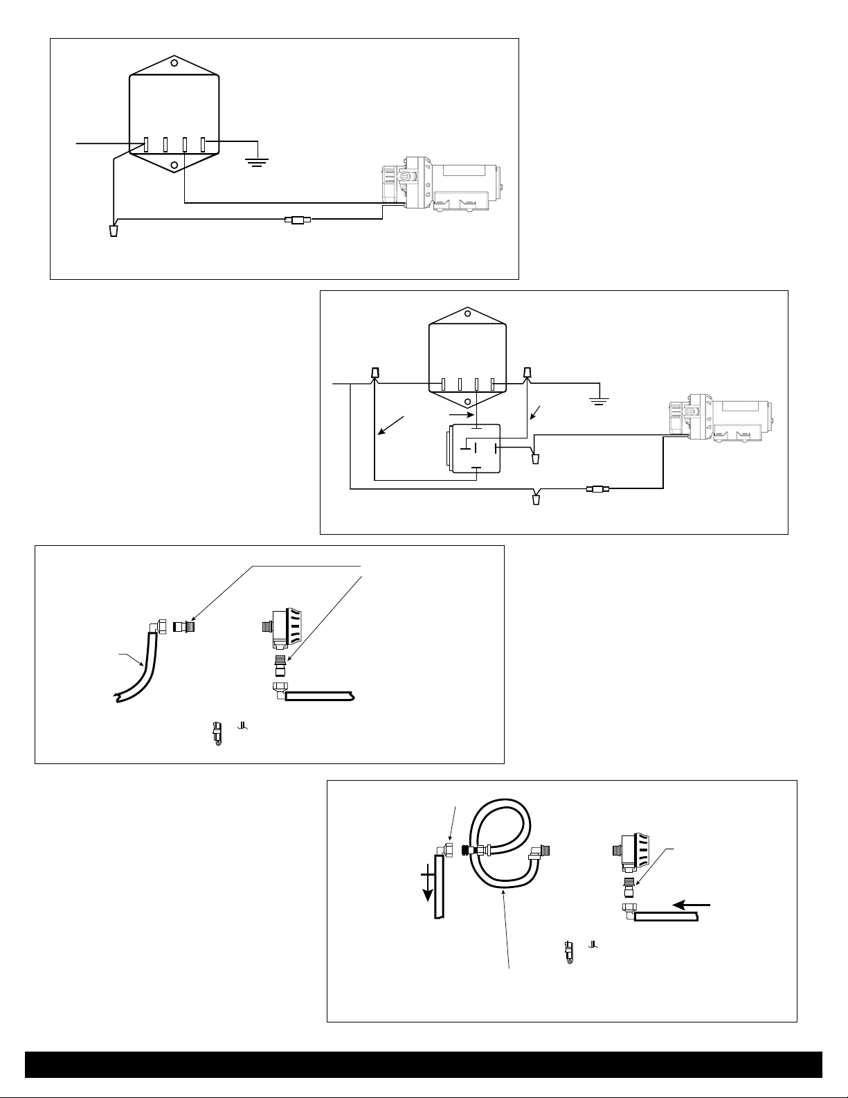
If necessary, please refer to Figures 1 and 2, page 4 for additional wiring instructions.
c. If there are two (2) or more switches in your RV that independently control your pump, you may experience
excessive voltage drops in your existing circuitry. Using voltmeter, test voltage at the pump with the pump running
(refer to Figure 1, page 4). With either a fully charged battery or a running generator, you should be getting at least
11 volts at the pump. If not, you should procure a 30 Amp rated relay as referenced above.
2. Determine the optimal location for the Aquajet pump. If possible, plan to position the Aquajet pump horizontally, with
its rubber feet resting on a “floor-like” surface rather than mounted on a wall. Never mount the pump in an area where
gasoline vapors are present, as the motor and heatsink of the speed-controller may get hot (up to 200 F) after extended
running. Locate the Aquajet pump at least one inch away from any wall surface. In most cases, you’ll be able to mount
the Aquajet pump very close to where the old pump was located.
3. Survey the existing plumbing and identify the suction line (i.e. the line going from the water holding tank to the pump).
For the quietest possible operation of the Aquajet pump, you should try to isolate the pump mechanically from your
RV’s typically hard Polybutylene or PEX tubing. If your RV is currently plumbed with soft-walled, reinforced hose (see
Figure 5, page 5), then your system should be perfectly suicient as is. By installing a piece of IAPMO approved cold
water hose (such as ‘Accuflex’ Series 136) between the pump outlet port and your RV’s hard plumbing, you will achieve
the quietest possible pump operation. Remco also oers, as an optional accessory, a 39” long pre-assembled hose with
fittings.
(Remco product number 25-174) that will adapt directly to the Aquajet pump and your existing plumbing. Please refer to
Figures 6 and 7, page 5-6.
Installation
1. Using Voltmeter, determine polarity of the wiring to the existing pump(s). Unfortunately, there is no standardized
color scheme for RV wiring (most RVs, however, seem to use red for the positive lead and black for the negative lead).
Regardless of your specific configuration, positive voltage (12VDC) must be connected to the RED (fused) leadwire of
the Aquajet pump. Reversing this polarity will instantly blow the in-line fuse and may permanently damage the controller.
Mark the positive (hot) RV wire with a piece of tape.
2. Turn power “o” to existing pump(s).
3. Open a faucet, bleed o all existing pressure, then close the faucet again.
4. Disconnect the main power to the pump (either at battery or fuse panel).
5. Remove the wire nuts from the leads to the old pump.
6. Steps 1 and 2 of the earlier ‘Installation Planning’ section should have determined the applicable wiring method. As
appropriate, wire the Aquajet pump as per Figures 1, 2, 3, 4 or 8, pages 4-6.
7. Connect outlet adapters
a. [For old pump outlets connected to hose, as in Figure 5, page 5] Insert O-ringed end of (Qest) threaded adapter
into outlet port (marked with arrow pointing away from pump) of the Aquajet pump. Lock fitting in place by pushing
down retainer slide.
b. For old pump outlets directly connected to hard tubing, as in Figure 6, page 5]. Insert the O-ringed elbow fitting
of the Accuflex hose adapter (sold separately) into the outlet port of the Aquajet pump. Lock fitting in place by
pushing down retainer.
8. Connect inlet adapters
a. [If the Aquajet pump is to be directly plumbed to the existing inlet filter/fitting, as in Figures 5 and 6, page 5]. Insert
the O-ringed end of threaded adapter into the pump’s inlet port (look for arrow pointing towards the center of the
pumphead). Lock fitting in place by pushing down retainer slide.
www.remcoindustries.com Page 3

PANEL
OLD
PUMP
SWITCH 1 SWITCH 2
MEASURE VOLTAGE WITH PUMP RUNNING
BATTERY
86
30
85
87
USE 15 AMP FUSE HERE
SWITCH 1
PANEL
MASTER SWITCH
ALTERNATE NEW HOT WIRE ROUTING NEW WIRE
OLD
GROUND
WIRE
SWITCH 2
OLD HOT WIRE TO PUMP
RELAY
40 AMP
NEW
10-12 AWG
HOT WIRE AQUAJET
PUMP
BATTERY
FUSE
15 AMP
b. [If the Aquajet pump is to be remote mounted, as in Figure 7, page 6]. Insert the O-ringed elbow fitting of the
Accuflex hose adapter (sold separately) into the inlet port of the Aquajet pump. Lock fitting in place by pushing
down retainer slide.
9. Remove the mounting screws from the old pump.
10. Place a towel under the inlet port (suction side) of the existing pump(s) and quickly remove the connecting fitting/filter.
11. Re-attach the filter/inlet fitting to the applicable adapter on the inlet side of the Aquajet pump.
12. If an Accuflex hose adapter is used on the outlet side (see Figures 6 and 7, pages 5-6), place the other end of the hose
adapter up high. This should stop water from being siphoned out.
13. Place a towel under the outlet port (pressure side) of the existing pump(s) and remove the connecting fitting.
14. Remove the old pump.
15. Position the Aquajet pump into its intended mounting place.
16. Drive the mounting screws (Remco recommends #10 screws, 1.5˝ long, to be used with washers) into the floorboard. Be
sure to stop just as the screw heads touch the washers so you do not compress the rubber mounting grommets.
1 7. Bleeding prep
a. [If you are plumbing per Figure 5, page 5] Place a bucket under your plumbing system’s pressure hose, have an
assistant open two inside faucets and drain water from the pressure line. Connect the pressure hose fitting to the
Qest adapter on the pump outlet side.
b. [If you are plumbing per Figures 6 or 7, pages 5-6] Place the open end of the Accuflex tubing from the Aquajet
outlet port into the bucket.
18. Reconnect the main power to the pump/relay using fuse box or battery.
19. Have an assistant briefly power up the pump using one of the RV’s standard “pump switches”.
20. Water should be flowing into the bucket (see Figures 6 and 7, pages 5-6) or into the sinks (see Figure 5, page 5).
21. Allow Aquajet RV to run for 10-15 seconds to get rid of all air inside the pump, then power down the pump.
22. Coil the Accuflex outlet tubing (pulsation dampener) and connect the pressure side Qest fittings. Use tie-wraps if
necessary to insure that the tubing will not rattle.
23. Power up the pump again and check for leaks. Tighten fittings where necessary.
24. Your pump should now be ready for use. Power down the pump when there is no need for water.
Figure 1: Typical RV two-switch wiring
Figure 2: New Aquajet Installation
www.remcoindustries.comPage 4

FUSE
15 AMP
BLACK
RED
GROUND+12V
OLD HOT
WIRE TO
PUMP
+12 5W LOAD
INTELLITEC
10 AMP
GND
AQUAJET
PUMP
FUSE
15 AMP
BLACK
GROUND+12V
NEW WIRE
NEW WIRE
+12 5W LOAD
INTELLITEC
7 AMP
GND
86
30
85
87
AQUAJET
PUMP
THREADED ADAPTERS
SUPPLIED WITH PUMP
FLEXIBLE HOSE
RV USES FLEXIBLE HOSE
FOR WATER LINES
POLYBUTYLENE
OR PEX
1/2” QEST
THREADED ADAPTERS
SUPPLIED WITH PUMP
INLET SIDE
(SUCTION)
OUTLET SIDE
(PRESSURE)
RV USES HARD TUBING
FOR WATER LINE
ADD “PULSATION DAMPENER”
REMCO P/N 25-174
(STRAIGHT 25-175)
Figure 3
Figure 4
Figure 5
Figure 6
www.remcoindustries.com Page 5

INLET SIDE
(SUCTION) OUTLET SIDE
(PRESSURE)
ACCUFLEX TUBING
REMCO P/N 25-174
(STRAIGHT 25-175)
ACCUFLEX TUBING
REMCO P/N 25-174
(STRAIGHT 25-175)
QEST ADAPTOR
QEST ADAPTOR
AQUAJET PUMP TO BE MOUNTED IN
DIFFERENT LOCATION THAN ORIGINAL PUMP
TO BATTERY +12V OR FUSE PANEL
INTELLITEC
7AMP
FIGURE 8
*NOT USED
86
30
85
87
GROUND BAR
BLACK
RED
SIGNAL
GROUND
+12V POWER
TO RADIO
*IGNITION
SPLICE
FUSE
15 AMP
AQUAJET
PUMP
Figure 7
Figure 8
TROUBLESHOOTING GUIDE
Aquajet RV Series | Aquajet ES Series
. PUMP DOES NOT RUN
Cause Solution
Tripped thermal protector/blown fuse Check fuse. If motor is overheated, allow it to cool down prior to restart.
Faulty wire connection or power source Check battery/power supply, polarity, main switch and wiring.
Pressure switch malfunctioning. Please contact factory, 1-800-228-2481.
Motor malfunctioning Replace pump.
Pump and/or motor is frozen Thaw pump and system and check for damage. The pump/motor may become
damaged when a frozen pump is started.
. PUMP RAPIDLY CYCLES ON/OFF WITH WATER DEMAND
Cause Solution
Hydraulic pulsations Install pulsation dampener. P/N 25-174 (elbow fittings) P/N 25-175 (straight fittings)
Restriction on outlet side of pump, resulting in
too much back pressure
Check inline filter, if any.
. PUMP RAPIDLY CYCLES ON/OFF WITHOUT WATER DEMAND
Cause Solution
Leak on outlet side of pump Check tightness of hose selections, check hose for possible damage.
Fill valve bypassing to tank Replace fill valve.
Debris under valves Flush pump in nominal flow direction. To flush pump: Turn on all the hot and cold
faucets all the way and let the water run for a few minutes.
www.remcoindustries.comPage 6

. PUMP DOES NOT PRIME
Cause Solution
Water tank empty Fill up tank.
Leak on inlet side of pump Check tightness of hose connections at pump, filter, and tank. Check valves at inlet
side.
Debris under valves Flush pump (in nominal flow direction) To flush pump: Turn on all the hot and cold
faucets all the way and let the water run for a few minutes.
Perforated diaphragm Please contact factory, 1-800-228-2481.
Inlet or outlet plumbing restricted Check plumbing. Water should free flow from tank at 2 GPM minimum.
. PUMP LEAKS
Cause Solution
Perforated diaphragm Please contact factory, 1-800-228-2481.
Inlet/outlet fittings leak Replace O-rings and/or fittings.
. PUMP KEEPS RUNNING WHEN WATER IS NO LONGER DEMANDED
Cause Solution
Diverter valve in “fill” mode Close and/or rotate any valve used for filling water tank.
Water tank empty Fill up tank.
Leak on outlet side of pump Check tightness of hose connections; check hose for possible damage.
Air leak on inlet side of pump Check tightness of hose connections. Check inlet hose, filter, and valves for possible
damage. Purge air.
Speed controller malfunctioning Please contact factory, 1-800-228-2481.
Low voltage to pump Change battery/power supply. Check wire gauge.
. LOW FLOW/PRESSURE
Cause Solution
Leak on inlet side of pump Check tightness of hose connections, check hose for possible damage.
Air in pump Purge air.
Low voltage to pump Change battery/power supply Check wire gauge.
Debris under valves. Flush pump in nominal flow direction. To flush pump: Turn on all the hot and cold
faucets all the way and let the water run for a few minutes.
Motor malfunction Replace pump.
. PUMP IS EXCESSIVELY NOISY
Cause Solution
Pump is plumbed directly to rigid tubing Install pulsation dampener. P/N 25-174 (elbow fittings) P/N 25-175 (straight fittings)
Restrictive inlet, pump is cavitating Check plumbing. Water should free flow from tank at 2 GPM minimum.
Pump head loose on motor Tighten screws.
Pump mounting is loose Tighten screws.
Pump mounting is too rigid Use flexible tubing and make sure the dampening rubber feet are used.
Defective motor/drive Replace pump.
. ELECTROMAGNETIC INTERFERENCE
Cause Solution
Noise can be heard in Stereo System, or TV picture
aected when pump is running
Install EMI filter in line with pump. p/n 21-256
Operation of Heating/Cooling System changes when
pump is running
Install EMI filter in line with pump. p/n 21-256
*No replacement parts are available for the Aquajet pumps.
www.remcoindustries.com Page 7

www.remcoindustries.com
MADE IN
AMERICA
The Standard For Professional Grade Diaphragm Pumps.
RI_AquaJetMan2020
Standard Warranty
REMCO warrants its products to be free from defects in material and workmanship on all products sold by REMCO for resale
or for use in purchasers’ own business or original equipment manufacturer. Under normal use, maintenance and service
(rental use excluded) the following terms apply:
For all REMCO products, the warranty will last for a period of one (1) year from date of manufacture, or one (1) year use with
proof of purchase, with the exception of the Aquajet pumps, which is two (2) years. REMCO’s obligation under this warranty
shall be limited to replacing or repairing, at REMCO’s discretion, any such product or part which must be returned to REMCO’s
factory with a Return Material Authorization number (RMA), transportation charges approved by REMCO or prepaid, and
which, upon examination, is found to REMCO’s satisfaction to have been defective under the terms of this warranty. No credit
will be allowed against future purchases for items returned as defective under the terms of REMCO’s warranty. REMCO
warrants all pump series to be free from material and workmanship defects (under normal use and service) for a period of
one (1) year from the date of manufacture, or one (1) year use with proof of purchase, with the exception of the Aquajet pumps,
which is two (2) years. This warranty does not extend to any products which have been altered or modified outside the REMCO
factory; to any products that have not been properly maintained; nor to units that are returned in an unassembled condition.
Furthermore, the warranty does not extend to pumps that are non-compliant with REMCO’s Engineering Standards. This
includes, but is not limited to, pumps ordered without an integral pressure control mechanism. The warranty guarantees that
products will perform to REMCO’s flow and pressure specifications throughout the life of the warranty. The warranty does not
cover wear, appearance, misuse, abuse, misapplication or external water damage. If the returned product is found not to be
defective under the conditions of this warranty, a charge will be made for repair or replacement.
Brush wear may be limited to 1000 hours or less.
This is a Limited Warranty. It covers the product only and the extent of the coverage is limited to the cost of the product. As
the manufacturer has no control over shipping, handling and installation, the warranty cannot cover water damage, or any
other damage, caused by a leak or other malfunction.
THIS WARRANTY IS IN LIEU OF ALL WARRANTIES, EXPRESSED OR IMPLIED, INCLUDING IMPLIED WARRANTIES OR
WARRANTIES OF MERCHANTABILITY AND/OR FITNESS FOR A PARTICULAR PURPOSE. NO PERSON IS AUTHORIZED TO GIVE
ANY OTHER WARRANTY OR ASSUME OBLIGATION OR LIABILITY ON REMCO’S BEHALF. REMCO SHALL NOT BE LIABLE FOR
ANY INDIRECT, INCIDENTAL, PUNITIVE OR CONSEQUENTIAL DAMAGES OF ANY KIND INCURRED BY THE REASON OF THE
USE OR SALE OF ANY DEFECTIVE PRODUCT AND PART. THIS WARRANTY SHALL BE GOVERNED BY THE LAWS OF THE STATE
OF MINNESOTA, WITH ANY DISPUTE OR CLAIM VENUED OR HEARD IN THE STATE OF MINNESOTA.
www.remcoindustries.comPage 8
This manual suits for next models
4
Table of contents
Other Remco Water Pump manuals
Popular Water Pump manuals by other brands

Meler
Meler Micron PUR LC quick start guide

Pfeiffer Vacuum
Pfeiffer Vacuum HENA 201 R operating instructions

Dual Pumps
Dual Pumps WBU8200P manual

BUSCH
BUSCH COBRA BA 0100 C instruction manual

Metabo
Metabo TP 7500 Si operating instructions

GORMAN-RUPP
GORMAN-RUPP PA Series Installation, operation and maintenance manual

Regulus
Regulus CSE SOL G SRS1 T-E Installation and operation manual

Aspen Pumps
Aspen Pumps Universal quick start guide

Wilo
Wilo Helix2.0-VE Installation and operating instructions

SFA
SFA SANICONDENS CLIM MINI installation instructions

PFT
PFT RITMO XL FC-230/400V operating manual

Antech
Antech LARA DS user manual