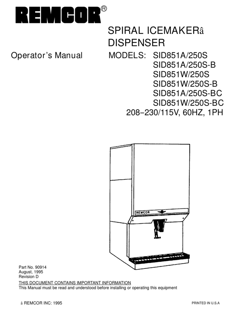
Remcor LP350A/150S User manual

SPIRAL LOW-PROFILE
ICEMAKER-DISPENSER
MODEL:
LP350A/150S,-B,-BC
LP650A/150S,-B,-BC
LP650R/150S,-B,-BC
Operator’sManual
PRINTEDIN U.S.A
âREMCORINC:1993 -1995
PartNo.91424
March 1997
Revision D
THISDOCUMENTCONTAINSIMPORTANTINFORMATION
ThisManualmustbe read and understood beforeinstalling oroperating thisequipment

i91424
TABLEOFCONTENTS
Page
SAFETY PRECAUTIONS1...................................................
DESCRIPTION2............................................................
UNPACKING2..........................................................
INSTALLATION3............................................................
LOCATION3............................................................
PLUMBING3...........................................................
MODEL LP650RONLY:REMOTECONDENSERINSTALLATION3............
ICEMAKER3..........................................................
REMOTECONDENSER4................................................
PRE-CHARGEDLINE SETS4............................................
ELECTRICAL(SEE FIGURE4)5.........................................
BEVERAGE SYSTEM8..................................................
BAG-IN-BOXOPTION8................................................
INSTALLATION8......................................................
STARTUP12................................................................
ICEMAKER12...........................................................
BEVERAGE SYSTEM12..................................................
ADJUSTINGWATERFLOW12............................................
BAG-IN-BOX(BIB)GAS OPERATEDSYRUP PUMPS 13.....................
OPERATING INSTRUCTIONS15...............................................
ICEMAKEROPERATINGINSTRUCTIONS15...............................
MAINTENANCE22...........................................................
CLEANINGINSTRUCTIONS22............................................
DISPENSERSECTION23...........................................
BEVERAGE/BAG-IN-BOX SYRUP SYSTEM23........................
MAINTENANCE/ADJUSTMENTPROCEDURE25................................
CLEARINGEVAPORATORFREEZE-UP25.................................
CLEANING/REPLACINGTHEFILTER25..................................
CLEANINGTHECONDENSER(AIR-COOLED UNIT)25......................
MANUAL FILLING26.........................................................
TROUBLESHOOTING GUIDE27...............................................
PARTSLIST38..............................................................
WARRANTY40..............................................................

i
i
91424
TABLEOFCONTENTS(cont’d)
LISTOF FIGURES
Page
FIGURE1.PRE-CHARGEDLINE SETS4..................................
FIGURE2.PRE-CHARGEDLINE SETINSTALLATION5.....................
FIGURE3.UNITSWITHBAG-IN-BOX PUMPOPTIONS6...................
FIGURE4.STANDARD UTILITYLOCATIONSREARVIEW7.................
FIGURE5.MODEL“B”FLOWDIAGRAM9................................
FIGURE6.MODEL“BC”FLOWDIAGRAM10...............................
FIGURE7.BEVERAGE SYSTEMSCHEMATIC11...........................
FIGURE8.LANCERVALVE 14.............................................
FIGURE9.LP350/150 WIRINGSCHEMATIC16..............................
FIGURE10.LP350 /150 115 /1/60 HZWIRINGDIAGRAM17...............
FIGURE11.LP650A/150 WIRINGSCHEMATIC18..........................
FIGURE12.LP650R/150 WIRINGSCHEMATIC19.........................
FIGURE13.REFRIGERATIONSCHEMATIC20..............................
FIGURE14.REMOTECONDENSERSYSTEMDIAGRAM21..................
LISTOF TABLES
TABLE1.SPECIFICATIONS2............................................
Manufactured UnderOne orMore of the Following PatentNumbers:
3,211,336,3,274,792,3,393,839 ,3,517,860,3,739,842,4,215,803,4,227,377,4,300,3594,346,824
Canadian PatentNumbers912,514 (10/72),936,855 (11,73),4,429,543,4,921,149
OtherPatentsPending

191424
SAFETY PRECAUTIONS
Always disconnectpowertothe dispenserbeforeservicing orcleaning.
Neverplace handsinside ofhopperorgate area withoutdisconnecting powertothe dispenser.Agitator rotation
occursautomaticallywhen the dispenserisenergized!
Thisice dispenserhasbeen specificallydesigned to provide protection againstpersonal injuryand eliminates
contamination ofice.Toinsurecontinued protection and sanitation,observethe following
ALWAYS be surethe removablelidisproperlyinstalled to preventunautho-
rized access tothe hopperinteriorand possiblecontamination ofice.
ALWAYS be surethe upperand lowerfrontpanelsaresecurelyfastened.
ALWAYS keep area around the dispenserclean oficecubes.
IMPORTANTINSTALLATION NOTICE
AnIMICorneliusmodelnumber81COR01PS,Filter MUSTBE INSTALLED inthe watersupplyline tothe ice-
maker.Failuretodosomayresultin poorqualityice,lowproduction outputand may cause prematurefailure of
icemakerevaporatorand voidthe extended evaporatorwarranty.
Thisicemakerisprovided withastainless steelevaporator,designed tolast the life of the product. However,
some of the chemicalsintreated and untreated water,specifically chlorine and sulfur (sulfide),havethe abilityto
attack stainless steeland cause prematurefailure.Aninitial investmentin properwatertreatmentwill payfor
itselfinincreased production,qualityand long life of the product.

291424
DESCRIPTION
The REMCORLOWPROFILE S.I.D.(SpiralIceâIcemakerDispenser) isa unique,self-contained, free stand-
ing style unitwhich automaticallymakeshard,clearcube-qualityice and storesitinasealed hopperforsanitary
dispensing.The iceismade bya new,patented process onaspiralshaped stainless steelevaporatorand pro-
ducestube cube qualityiceonthe outside of the tubes.There are no augers,no compressing of flaked ice,no
bearingsand no high gear motorloadsinthe icemaking process.The unithasbeen designed tobesimple,yet
effective, to provide many yearsof troublefree operation.
Table 1.Specifications
ModelLP350ALP650ALP650R
Compressor:HP1/2HP3/4HP3/4
Refrigerant: R-22 /1lb.R502 /2lbs.R502 /8lbs.
Voltage:115 /1/60 115 /1/60 115 /1/60
Amps:16 Amps16 Amps16 Amps
CircuitAmpacity:*20 Amps20 Amps20 Amps
FuseSize:20 Amps TimeDelay20 Amps TimeDelay20 Amps TimeDelay
IceStorage Capacity:150 lbs.150 lbs.150 lbs.
IceMaking Capacity:Upto 350 lbs./24 hrs.650 lbs./24 hrs.650 lbs./24 hrs.
NOTE:*30 ampswhen unitis suppliedwithcarbonator.
UNPACKING
1.Withthe unituprightcarefullyremovethe shipping carton. Inspect forshipping damage and reportany
such damage tothe shipperimmediately.
2.Removelowerfrontlouvered panelforelectricaland start-up process.
3.Removeshipping tape fromstorage hoppercoverand agitatorinstorage hopper.

391424
INSTALLATION
WARNING:Onlyqualified personnelshouldservice internalcomponentsorelectrical
wiring.
LOCATION
Locatethe icemakerdispenserindoorsinawell ventilated area.Avoid exposureto directsunlightand/orheat
caused byradiation.Ambientroomtemperaturemustbe inthe range of60°to 90°F.Do notinstall unitin an
enclosed area where heatbuild-up couldbeaproblem.Note:Airflowdirection and spacing required shownin
Figure 1.
ConsultFigure1forutility connection locations.
PLUMBING
Connect the icemakertoacold,potablewatersource,suitablefordrinking.Thiswatersourcemustcomplywith
the basicplumbing code of the Building Officialsand Code AdministratorsInternationalInc.(BOCA)and the
Food ServiceSanitation Manualof the Food and Drug Administration.Do notinstall unitonawatersoftener
line.Itisrecommended thata hand shut-off valve and strainerbe used on the incoming supplyline.(See Figure
1forsize and location.)Forproperoperation of the incoming watersupplypressuremustbe inthe range of
30-90 PSIG. Install a pressureregulating valveifabovethisrange!
IMPORTANT:To insurepropericemakeroperation and alsotoreduce thefrequency ofwater-related
service problems,awaterfiltershould beinstalled.REMCORrecommendstheuse ofIMICornelius
filter,modelnumber81COR01PS.
Forspecificrecommendationson thesefiltersystemsforyourlocal waterconditions,consultwithadistributorin
yourarea orcontact the filter manufacturer.
Connectseparate drainlinesto all drainconnections.See Figure2forsize and location.Theselinesmustpitch
downwardto and open drain and mustcontainnotraps,orimproperdrainage will result. All drainconnections
mustbe in accordancewiththe basicplumbing code of the Building Officialsand Code AdministratorsInterna-
tional(BOCA)and localcodes.
NOTE:Inareas where consistentlywarmwatertemperatures are encountered,theuse ofapre-cooler
inthewaterlineisrecommendedtomaximizetheice production of thisunit.
MODEL LP650RONLY:REMOTECONDENSERINSTALLATION
RemcorProductsremotecondensersystems comeinthree separate packagestocomplete one remotecon-
denserapplication.They consistof the icemaker, the remotecondenserand the interconnecting pre-charged
line set.
Icemaker
The refrigeration systemofaremotecondensersystemsis similartoastandard aircooled systemwiththe fol-
lowing exceptionsdescribed below:
Mixing Valve
This valveislocated at the condenserand servesasa head pressureregulating valve.Asthe temperature at
the condenserdrops, the head pressure at the receiverwill drop.When thispressurereaches225 PSIG, the
mixing valve by-passesthe condenserand metershotdischarge gasintothe receiver,maintaining the 225
PSIG receiverpressure.

491424
LiquidReceiver
Inthe icemaker,a 10# liquidreceiverisinstalled to accept the large refrigerantcharge thatisnotneeded when
the condenseris subjected to highertemperatures.
PumpDownSystem
To preventrefrigeration migration tothe compressorduring the off-cycle due torefrigerant to oil attraction or
temperature differentialbetween condenserand compressor,a pump downsystemhasbeen utilized inthisre-
motecondensersystem.
Asolenoidvalve hasbeen installed inthe liquidline tothe TXV and isopen during normal icemaking operation.
When the binstatopens, the solenoidvalveclosesand stopsthe flowofrefrigerant tothe lowside of the sys-
tem.The compressoris keptrunning bythe pump downlowpressurecontrol, therebypumping anyremaining
refrigerantoutof the lowside intothe high side liquidreceiver.When the lowdie pressuresreaches5# the com-
pressoristurned off. The lowside control isarecycling controland ifrefrigerantleaks intothe lowside and the
pressuresreaches55# the compressorisrestarted,removing the unwanted refrigerant.
REMOTECONDENSER
The remotecondenserisan air-cooled fin-pack thatcan be mounted inthe horizontalorverticalposition.Care
shouldbetaken inthe installation sitetoreduce prevailing wind restraintsand tokeep the airentrance away
fromothersystemsairdischarge.Thiswill keep the remotesystemoperating atits’ designed efficiencies.
Thisremotecondensersystemisdesigned to operateintemperaturesof--20 degrees F through 120 degrees F.
Theselimits shouldbeconsidered when installing equipment.
The remotecondenseris supplied withalowambientmixing valvethatassuresthat the receiverwill underall
temperatureshavealiquid pressure of225 PSIG. Thisisrequired forpropertxv operation and to assuresuffi-
cientpressurewhen hotgasby-pass isrequired.This valve eliminatesthe requirementofanyfan cycling con-
trols.
The remotecondenserisnotrequired tocyclewiththe hotgasportion of the icemaking cycle.The wiring of the
condensercan eitherbe wired toaseparate powersource or, to allowthe condensertoshutdownwiththe ice-
maker,itmaybe wired perthe electricaldiagramenclosed.
NOTE:Whenservicing remote condensermake surethepowerisdisconnected.
Electricalvoltage requirementsarerated on the condenserforseparate powersourcing.
PRE-CHARGEDLINE SETS
The pre-charged line sets(25 ft. long or40 ft. long)jointogetheratotally sealed pre-charged system readyfor
operation afterinstallation.The line setis supplied with 3/8”quick couplingsforthe liquidline and 1/2”quick
couplingsforthe discharge line.Asthesecouplingsare“one time”couplings,if theyare ever removed and re-
installed, the system refrigerantcharge will be lostand an evacuation and recharge of the systemwill be neces-
sary.
LIQUIDLINE
3/8-IN.DIA.
REMOTE
CONDENSER
DISCHARGELINE
1/2-IN.DIA.
ICEMAKER
FIGURE1.PRE-CHARGEDLINE SETS

591424
When routing pre-charged line set, makesurethatcouplingsarelubricated withrefrigerantoil to assure proper
troublefree assemble.
6-HOLEFLANGE
PARTNO.150-22
5502 COUPLING
HALF TALL FLANGE5505 COUPLINGHALF
UNION NUT
PANELOR BULKHEAD
FIGURE2.PRE-CHARGEDLINE SETINSTALLATION
1.Remove dustcap and plugsifused,making surethatcomponentsynthetic sealsareintact.
2.Wipe off coupling sealsand threaded surfaceswithaclean clothto prevent the inclusion ofdirtoranyfor-
eign material inthe system.
3.LUBRICATErubberseal inmale halfwithrefrigeration oil.Thread coupling halvestogetherbyhand toin-
sure proper mating of threads,Use propersizewrenches(on coupling bodyhexand on union nut)and
tighten until coupling bodies“bottom”ora definiteresistanceisfelt. Usingamarkerorinkpen,markaline
lengthwisefromthe coupling hextothe bulkhead. then tighten an additional1/6to 1/4turn.The misalign-
mentof the line will showthe degree of tightening.Thisfinalturnisnecessarytoinsurethat the knife edge
metalsealbitesintothe brass seatof the coupling halves, forming the leakproofjoint. If torque wrenchis
used, the following torque valuesarerecommended:
Coupling SizeFt. Lbs.
--8 35
--12 50
--16 65
Routing ofline setsareaveryimportant factorintroublefree installation.
1.Makesurecondenserwill be located abovethe icemaker.
2.Routeline setstokeep excess tubing inside ofbuilding.
3.When coiling excess tubing makesurecoilsruns verticallywiththe flowofrefrigerant.
ELECTRICAL(see figure4)
A4X2junction boxislocated at the rearof the unit forthe supplyhook-up.Connect the icemakertoits’ own
individualcircuitperthe NationalElectricCode and Local Code (see SPECIFICATIONSforampacityand fuse
size).
IMPORTANT:Thewire sizemustbe adequateforthe ampacityrating and the supply voltagemustbe
withinarangeof±10%forpropericemakeroperation.
NOTE:That theunitrequires a 2-wire systemsplus earth ground forproperoperation.

691424
PUSHFORICE
STRAWS
CUPS CUPS CUPS CUPS
34 3/4
30 10 1/2
10
32 3/8
26 1/4
15 5/8
6 3/8
AIRFLOW
OPENINGFOR BEV
LINES 6 1/2X8 1/2
KICK PLATE
REMOVABLE
(OPTIONAL)
1 1/28
30
5 1/2
2
AIRFLOW
4 1/8
34
32
11
1/2
45
64 3/8
AIRFLOW
3 19/325 3/4
AIRFLOW
AIREXHAUST
(LEFT OR RIGHTSIDE)
ALL PANELS
REMOVABLE
FRONTAND SIDEKICK
PLATE(OPTIONAL)
BAGIN BOX SYRUP
PUMPS (8) (OPTIONAL)
SINK
OPTIONAL
OPTIONAL
TOPACCESS FORMANUAL
FILL OFHOPPER
FIGURE3.UNITSWITH BAG-IN-BOX PUMPOPTIONS

791424
(LOWER REAR LOUVEREDPANELREMOVED)
LP650RONLY:REMOTE
CONDENSERLINE
CONNECTIONS
*115V,1/4HP,4AMPREMOTE
FAN MOTORFOR REMCOR-SUPPLIED
REMOTECONDENSER
OPTIONALCARBONATOR
*LP650RONLY:
4? X2? HANDYBOXFOR REMOTE
CONDENSERFAN HOOKUP
GREEN(GROUND)
BLACK (HOT)
4? X2? HANDYBOXFOR
SUPPLYHOOKUP
WHITE(NEUTRAL)
SUPPLYCONDUIT(ROUTE
THROUGH BOTTOMOPENING)
2 7/8
1 1/4
22 7/8
4 1/2
ROUTEALL UTILITIES THROUGH BOTTOMOPENING:
1. ICEMAKERWATERIN3/8-IN. I.D.TUBING
2.CARBONATEDWATERIN3/8-IN. I.D.
3.TUBING(COLDPLATEUNITS)
4.DRAIN1-IN. I.D.BY1 1/4-INO.D.TUBING
FIGURE4.STANDARD UTILITYLOCATIONSREAR VIEW

891424
BEVERAGE SYSTEM
“B”,“-BC”Models:connect the beverage systemproductlinesasindicated in“B”and “BC”units,Figures5 and
6respectively.Thiswork should be down bya qualified service person.Notethat the hosesaremarked with
numberS1,etc. forsyrup connection and “CW”forcarbonated waterconnections.
Bag-In-BoxOption
The unithasa built-incold plate,carbonator,beverage faucetsand syrup pumps.Itisdesigned tobesupplied
directlyfromthe Bag-in-Box syrup containerswith no additionalcooling required.(see Figure 7)
Installation
1.Connect the beverage systemsyrup lines(tubing marked S1through S10)tothe Bag-in-Box containers.
2.Hookup the carbonatorwaterline (marked “CW”)to a potablewatersupply.
3.Hootup the carbonatorand syrup pumpCO2line (marked “CO2”)tothe CO2supplytank.
NOTE:Thiswork should bedonebyaqualifiedservice person.

991424
ITEMS OUTSIDE BROKEN LINES
ARE NOT INCLUDED. (2) CENTER
FAUCETS CAN BE CONVERTED
TO NON--CARBONATED WATER.
4 ADDITIONAL FAUCETS AND TANKS
(7 THRU 10) ARE PERMITTED
5 -- 15
PSIG
OPTIONAL FOR
DIET OR ROOT
BEER
OPTIONAL PRESSURE
REGULATOR
SYRUP
TANKS
FOR REFERENCE ONLY
NOT FOR CONSTRUCTION
WATER
SUPPLY
60 -- 100 PSIG
FILTER
CARBONATOR
COLD PLATE
REGULATORS
CO2TANK
FAUCETS
FIGURE5.MODEL“B”FLOWDIAGRAM

1091424
REGULATORS
CO2TANK
SYRUP
TANKS
60--100 PSIG
OPTIONAL
PRESSURE
REGULATOR
WATER
SUPPLY
FOR REFERENCE ONLY
NOT FOR CONTRUCTION
FILTER
OPTIONAL
FOR DIET OR
ROOT BEER
5--15
PSIG
4 ADDITIONAL FAUCETS AND
TANKS (7THRU 10) ARE PERMITTED
CARBONATOR
COLD PLATE
ITEMS OUTSIDE BROKEN LINES
ARE NOT INCLUDED (2) CENTER
FAUCETS CAN BE CONVERTED
TO NON-CARBONATED WATER
FAUCETS 15-50 PSIG
FIGURE6.MODEL“BC”FLOWDIAGRAM

11 91424
2
1 2 3 4 5 6 7 8
DETAILA
CARBONATED
WATERCO2CHECK
VALVE
DUALCHECK
VALVE
WATER
PUMP
CARBONATOR
WATER
TANK
PLAINWATER
TO
ICE
MAKER
CHECK VALVE
OPTIONAL
PRESSUREREGULATOR
WATER
SUPPLY
90-100 PSIGREGULATOR
CO2TANK
12345678
SYRUPOUT
(TYP)
BAG-N-BOX
PUMPS (8)
TOBAG-N-BOX
SYRUP(8)
CO2(50PSI)
TYP
BAG-N-BOX
SYRUP(TYP)
1 876543CW
ICECOOLED
COLDPLATE
21 3456 7 8
SEE DETAILA
FAUCETS
(FRONTOFUNIT)
SYRUP PUMPCO2
REGULATOR(50PSIG)
SYRUP PUMP
DISTRIBUTOR(CO2)
FIGURE7.BEVERAGE SYSTEMSCHEMATIC

1291424
STARTUP
ICEMAKER
1. Open the hinged top cabinet. Removeice drop coverand storage hoppercover.Removethe lowerfront
paneldirectlyabovethe sink.
2.Turnonwatertoicemaker.
3.Depress the switchtoverifythatwaterinletvalve operatesand that the waterdrainline isopen and not
plugged.Continue to depress switch until waterisobserved flowing in“diameterclearicemakerdrainline.
4.Put the “stop/run”switchinthe “run”position. Observethat the icemakergoesthrough propericemaking
and harvestcycles.Ifunitmalfunctions,consult the TROUBLESHOOTING GUIDE.
NOTE:Dotomeltageloss because ofwarmstoragehopper, itwill take longertofill thehopperthe
first timethanwhentheicemakerhas been operating continuously.
5.Depress the vend switchlever.Check thatboththe gatesolenoid and agitator motorare energized simulta-
neouslytolift the gateslid and rotatethe agitatorinthe storage hopper,respectively.Ifeithercomponent
malfunctions,consult the troubleshooting guide withwaterbeforestarting unit. Put the stop/rumswitchin
the “run”position. Observethat the icemakergoesthrough propericemaking and harvestcycle.Ifunitmal-
functions,consultTROUBLESHOOTING GUIDE.Replacethe ice drop and hoppercovers.
BEVERAGE SYSTEM
6.Startup the beverage systemand adjust the faucetstothe properbrix,according tothe following steps. It
will take approximatelyone (1)hourfromthe initialmachine start-up forthe cold plateto be at full capacity.
7. turn on and setCO2pressureonCO2tankregulatorto 100 PSIG.
8.Purge all carbonated plainwaterlinesuntil asteady streamofwaterflowsoutofeachfaucet.
ADJUSTINGWATERFLOW
9.Allowunit tomake enough icetocoverthe cold plate(approximatelyone hourfrominitialstart-up).
A.The waterflowmaybe adjusted to 2.50 oz/sec(74 ml.sec).Thiswill produceafinished drinkflowof
3.0 oz/sec(88.8ml/sec).
B.Slide up I.D.paneluntil flowcontroladjustmentsare exposed (see Figure 8).
C.Remove nozzle bytwisting counterclockwise and pulling down.
D.Remove diffuserbypulling down.
E. Install Lancer (yellow)Syrup Separatorin place ofnozzle.
F.Activatevalvetofill separatorsyrup tube.
G. Holdabrix cup underthe syrup separatorand dispensewaterintocup for3seconds.The water
should be even withthe top line (FFV).
H.To obtain desired waterflowrate,useascrewdriverto adjustwaterflowcontrol(See Figure 3).

13 91424
BAG-IN-BOX(BIB)GASOPERATEDSYRUP PUMPS
10.Connectall BIBconnectorsto appropriateflavorsyrup,matching the faucet flavor (S1toFaucet#1,etc.).
11.Removetop lowerpanelon the unit(justbelow)the beverage faucets)to access the CO2distributor man-
ifold.TurnonCO2supply(50 PSIG)to each pump atmanifold.Pumpswill run until the syrup linesare
pressurized and will automatically shutoff. Operate eachfaucetuntil asteady streamofsyrup isdispensed
free ofairbubbles.
12.Adjusting watertosyrup ratio(BRIX).
A.Holdthe BRIXcup underthe syrup separatorand activate.Check ratio(BRIX).
B.To obtain desired ration,usescrewdriverto adjustsyrup flowcontrol,(see Figure 8),until the syrup
and waterlevelsare even.
Usethe 5:1ratioforall flavorsexceptdietCoke.Usethe 5.5:1ratiofordietCoke.
C.Removesyrup separator.
D. Install diffuserand nozzle.
E.slide downI.D.panel.
NOTE:There are syrup and watershut-off valves locatedat theback ofeachfaucet.These should be
fullyopenatall times and onlybe closedforservice ofifaleak occurs.
13.Aftercompletion of the start-up procedures,clean the unit. (See CLEANING INSTRUCTIONS).

1491424
DATEOFMANUFACTURE
SERIES NO.
SHUTOFF CLOSEDSHUTOFF OPEN
WATERSYRUPSYRUPWATER
INCREASE DECREASE
COVER
INCREASE DECREASE
FLOWCONTROL
SYRUP
FLOWCONTROL
WATER
COVERMOUNTING
SCREW
I.D.PANEL
(SHOWNINOPEN
POSITION)
CUPLEVER
SODA LEVER
(OPTIONAL)
NOZZLE
FIGURE8.LANCERVALVE

15 91424
OPERATINGINSTRUCTIONS
ICEMAKEROPERATINGINSTRUCTIONS
Atemperaturesensing bulblocated inthe storage hopperstartsand stopsthe icemaking process (compressor)
inresponsetothe icelevel inthe hopper.Withthisicelevelcontrol“calling”forice(hoppericelevel islow), the
totalcycletimerenergized.Thistimer,inturn energizesthe harvestand agitation timersfortheir respective
“on”times.The chartbelowdetailsthis sequence ofevents:
CONTROLLER
TimeTotalCycle
TimerHarvest
TimerAgitation
TimerAction
Start-34 secondsX1.Hotgas solenoidvalve open.
34 -37 SecondsX1.Agitator motoron.
34 -X1.Harvestmotoron.
2.Waterfill valve on.
55 -** XX1.Harvestand agitator motorsoff.
2.Waterfill valve off.
34 -*X1.Hotgas solenoidvalveclosed.
*LP350 -510 seconds** LP350 -55 seconds(21 sec.harvest)
LP650 -570 secondsLP650 -75 seconds(41 sec.harvest)
At the 34 second pointinthe cycle, the hotgas solenoidvalveclosesand ice beginstoform on the stainless
steeltubing coilsof the evaporator. Icewill continue toform on thesecoilsforthe remainderof the cycletime
(*seconds).At the end of the icemaking cycle, the totalcycletimer (repeat)startsthe harvestportion of the
cycle again.
When icecontactsthe controlbulbinthe storage hopper, the controlswitchesthe compressoroff. This control
(thermostat)alsoswitchesoff powertothe totalcycletimer.With powerde-energized, the timer resetsitself to
the “start”portion of the cycle.Therefore, the unitwill always startwiththe hotgas/harvestportion of the ice
making cycleto ensurethat the evaporatoris cleared ofanyremaining ice.

91424 16
RED
TOTALCYCLE
TIMER
3
FLIGHTED DISPLAY
WHT
RED
R
E
D
BRN
BLK
R
E
D
R
E
D
RED
BLK
AGITA-
TION
TIMER
YEL
BLK
B
L
U
E
R
E
D
HARVEST TIMER
BEVERAGETRANSFORMER
24 VTO BEVERAGEFAUCETS
BLUBLUORGBLK
WHTBLK
C
NO
NC
NC
NO
C
L1L2
COM
NO
NC NC
NO
COM
COM
NO
NC NC
NO
COM
L1
L2AGITATORMOTOR
CWROTATION
TP
YEL
BLUE
AUX
CAP
MAIN
SUMP PUMP
CARBONATOR
MOTOR HEATER
DUPLEX
C
NC
FILL
SWITCH
NO
21
CONDENSERFAN
STOP/
RUN
BLUE
CLEAN
RUN
115/1/60 Hz
F
CAP
VEND SWITCH GATE SOLENOID
WATERFILL VALVE
HGSOL VALVE
AIR PUMP
HARVESTMOTOR
BIN T’STAT
LPS
HPS
S
R
C
TP
START
RELAY
STARTCAP
COMPRESSOR
N
L
RED
RED
WHT
BLK
WHT
WHT
WHT
REDWHT
RED
BRN
WHT
WHT
RED
REDWHT
BLKBLK
BLK REDWHT
BLKWHT
BLKWHT
BLKWHT
FIGURE9.LP350/150 WIRINGSCHEMATIC

17 91424
WHT. RED
RED
START
RELAY
WHT BLK
BLK
WHT
WHT
BLK RED
RED
RED
WHT
BLK
BLUE YEL
WHT
YEL
ORG
RED
YEL
WHT
WHT
WHT
GRN
RED BLK
RED
BLK
BLK
RED WHT GRN
BRN
WHT
RED
BLK
WHT
BLUE
BRN
BLK
BLK
BLUE
WHT
RED
RED
RED
RED
RED
WHT
WHT
RED
F
C3
1
S
LIGHTED
DISPLAY
STARTER
LIGHT
BALLAST
L2L1
AGITATION
TIMER
TOTAL CYCLE
TIMER
HARVEST TIMER
FILL
SWITCH
RUN
CLEAN
FUSE 1- -1/4 AMP
TIME DELAY
RUN
STOP
DUPLEX
RECEPTACLE
SUMP PUMPPLUGGEDINTO
DUPLEXCARBONATOR
BEVERAGE
SYSTEM
TRANSFORMER
24 VOLTS TO
BEVERAGE SYSTEM
BLUE
BLUE
BLK
WHT
YELBLUE
RED
BLK
AGITATOR
MOTOR
WHT
GRN
WHT
BLK
115V,60HZ,1Ph,30AMP.
FIELD SUPPLIED
JUNCTION BOX
POWER IN
RED
GATE
SOLENOID
AIR PUMP
ORN
BLUE
WATER FILL
VALVE
BRN
WHT
LPS
HGSOLVALVE
2
BIN
T”STAT
BLUE
YEL
REDCOMPRESSOR
STARTCAP.
R
BLK
COMPRESSOR
MOTORWHT
RED
HARVEST MOTOR
WHT
NC
NO
CL1
L2
R
E
D
BLK.
HIGH PRESSURE
SAFETY CONTROL
NCNO
C
MOTOR HEATER
VEND
SWITCH
RED
RED
YEL
RED
SC
RED
REDBLUE
BLUE
12
3REDBLUE
BLUE
WHTBLUE
BLUE
C
NO
NC
C
NO
NC
C
NO
NC
NC
NO
C
L1L2
NO
NC
C
BLK
RED
C
NC
NO
WHT
BLK
BLUE
WHTBLK
BLKYEL
WHT
NOTES:
1.BLACK PRINTING ONWHITE BACKGROUND.
2.ADHESIVE PROTECTIVE BACKINT TOBE SUPPLIEDWITHATAB ORSLIT FOREASY REMOVALFROMLABEL,
3.ARTWORKTOBE SUPPLIEDBY REMCO.
4.MATERIALSPECIFICATIONS:
GLOSS 60 LB.LITHOPAPERWITHPERMANANTS246 ACRYLICADHESIVE.
ACCEPTEDVENDOR
GRAPHICSOLUTION
FIGURE10.LP350 /150 115 /1/60 HZWIRINGDIAGRAM
This manual suits for next models
8
Table of contents
Other Remcor Dispenser manuals