Remcor TJ150-B User manual

ICE/BEVERAGE DISPENSERS
MODELS:TJ150-B
TJ150-KB
TJ150-BC
TJ150-KBC
Operator’sManual
PRINTEDIN U.S.A
âREMCORINC:
PartNo.90956
February,1997
Revision E
THISDOCUMENTCONTAINSIMPORTANTINFORMATION
ThisManualmustbe read and understood beforeinstalling oroperating thisequipment

i90956
TABLEOFCONTENTS
Page
SAFETY PRECAUTIONS1...................................................
GENERALDESCRIPTION1..................................................
ICEMAKER2...........................................................
INSTALLATIONINSTRUCTIONS3............................................
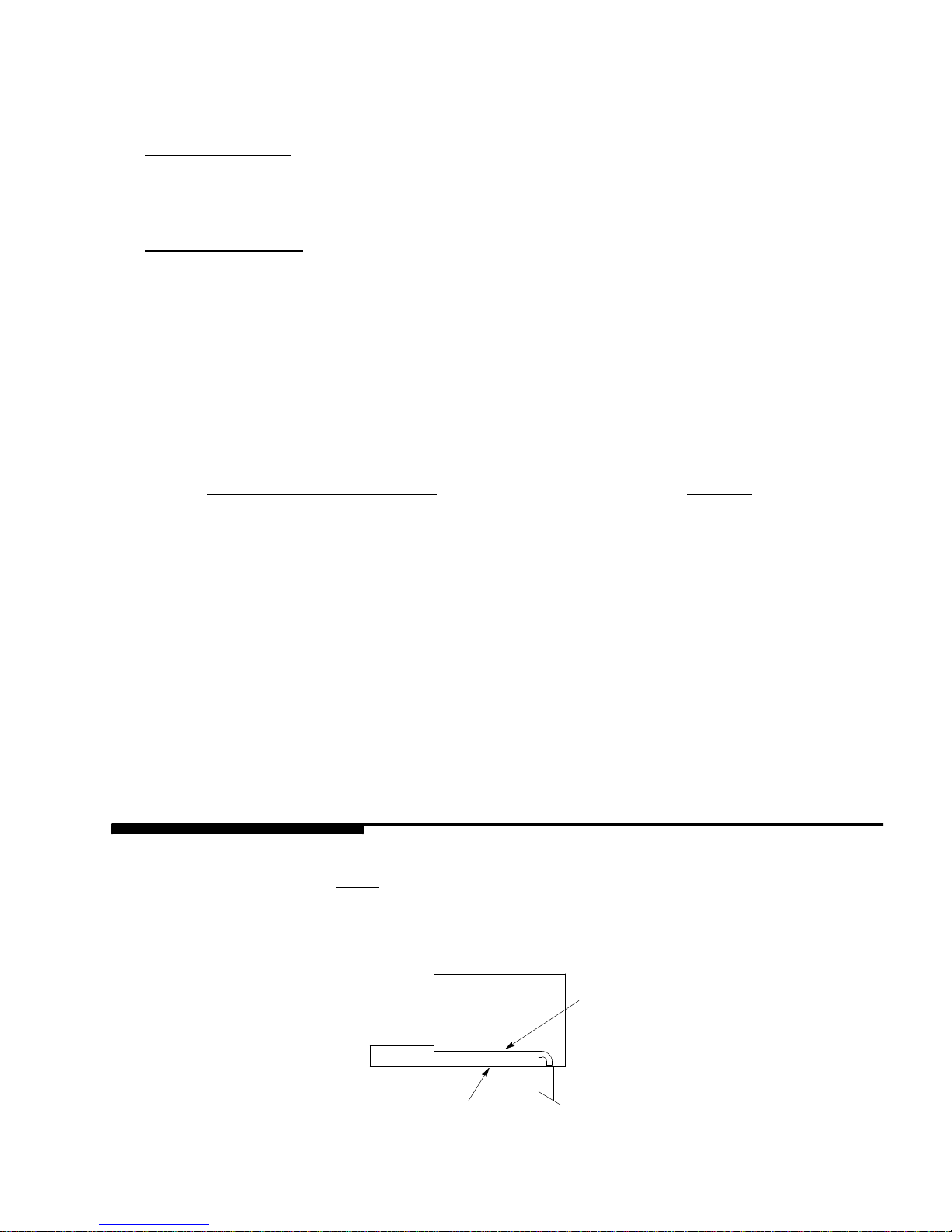
SINKDRAINASSEMBLYINSTRUCTIONS3................................
CLEANING INSTRUCTIONS4................................................
DISPENSER4..........................................................
COLDPLATE4.........................................................
BEVERAGE SYSTEM5..................................................
MAINTENANCE6...........................................................
DAILYORAS REQUIRED6..............................................
WEEKLYORAS REQUIRED6............................................
MONTHLY6............................................................
OPERATING INSTRUCTIONS6..........................................
GATERESTRICTORPLATE7............................................
ADJUSTMENT7........................................................
TROUBLESHOOTING GUIDE8...............................................
BLOWNFUSE OR CIRCUITBREAKER8..................................
GATEDOES NOTOPEN.AGITATOR DOES NOT TURN 8...................
GATEDOES NOTOPENORIS SLUGGISH.AGITATORTURNS.8...........
GATEOPENS.AGITATOR DOES NOT TURN.8............................
ICEDISPENSES CONTINUOUSLY.8......................................
SLUSHYICE.WATERIN HOPPER.8......................................
ICE SOLIDIFIEDIN HOPPERORICE ATREAR CORNERONLY.8...........
NO ICEIN HOPPER8...................................................
ICE PACKEDIN HOPPER8..............................................
BEVERAGES DONOTDISPENSE 8......................................
BEVERAGES TOO SWEET.8............................................
BEVERAGES NOTSWEETENOUGH.8...................................
BEVERAGES NOTCOLD(UNITSWITHBUILT-IN COLDPLATE).8...........
FINALASSEMBLY PARTSLIST16............................................
WARRANTY18..............................................................
Manufactured UnderOne or More of the following PatentNumbers:3,211,336,3,274,792,3,393,839,3,517,860,
3,739,842,4,215,803,4,227,377,4,300,359,4,346,824
Canadian PatentNumbers:912,514 (10/72),936,855 (11/73),4,429,543,4,921,149
OtherPatentsPending

i
i
90956
TABLEOFCONTENTS(cont’d)
LISTOF FIGURES
Page
FIGURE1.SINKDRAINASSEMBLY3.....................................
FIGURE2. GATERESTRICTORPLATE7..................................
FIGURE3.TJ150-KICECUBERINSTALLATION9.........................
FIGURE4.MOUNTINGTEMPLATETJ150-B,BC10.........................
FIGURE5.SPECIFICATION DRAWINGTJ150-B,BC11......................
FIGURE6.BEVERAGE SYSTEMSCHEMATIC“-B”MODELS12..............
FIGURE7.BEVERAGE SYSTEMSCHEMATIC“-BC”MODELS13.............
FIGURE8.WIRINGDIAGRAMTJ150-BC DISPENSER14....................
FIGURE9.FINALASSEMBLY15..........................................
FIGURE10.SOLENOIDASSEMBLY17.....................................
LISTOF TABLES
TABLE1.SPECIFICATIONS1............................................

190956
SAFETY PRECAUTIONS
Thisice dispenserhasbeen specificallydesigned to provide protection againstpersonal injuryand eliminate
contamination ofice.To ensurecontinued protection and sanitation,observethe following:
Always disconnectpowertothe dispenserbeforeservicing orcleaning.
Neverplace handsinside ofhopperorgate area withoutdisconnecting powertothe dispenser.Agitator rotation
occursautomaticallywhen the dispenserisenergized!
ALWAYS be surethe removablelidisproperlyinstalled to preventunautho-
rized access tothe hopperinteriorand possiblecontamination ofice.
ALWAYS be surethe upperand lowerfrontpanelsaresecurelyfastened.
ALWAYS keep area around the dispenserclean oficecubes.
CAUTION:Dispensercannotbeusedwithcrushed orflakedice.
Use ofbaggedice,thathas frozenintolarge chunks,canvoidwarranty.Thedispenser
agitatorisnotdesignedto be anice crusher.Use oflarge chunks ofice that“jamup”
insidethehopperwill cause failureof the agitator motorand damagetothehopper. Ifbaggedice
isused, itmustbe carefully and completelybrokenintosmall, cube-sized pieces beforefilling into
thedispenserhopper.
GENERALDESCRIPTION
The Remcor“TJ”seriesofice and beverage dispensers solveyourice and beverage service needsthe sani-
tary,spacesaving,economical way.Designed tobemanuallyfilled withicefromanyremoteicemaking source,
orautomaticallyfilled fromatop-mounted “icecuber,”these dispenserswill dispensecubes(up to1? insize),
cubelets,hard-chipped orcracked ice and in addition,severalflavorsofpost-mixbeverages.“B”models contain
beverage faucetsonlyand mustbe supplied withcold product fromanyremotecold plate or refrigerated soda
factory.“-BC”modelsinclude faucetsand a coldplate and are designed tobesupplied directlyfromthe syrup
tanks and carbonator,with no additionalcooling required.
Table 1.Specifications
Model:TJ150E/S-B,“KB”
IceStorage:150 lbs.
Electrical:120 /1/60
MaximumNumberofFaucetsAvailable:8
Dimensions:30? Wx30? Dx34-1/2? H
Model:TJ150E/S-BC,“KB”
IceStorage:150 lbs.
Electrical:120 /1/60
MaximumNumberofFaucetsAvailable:8
Dimensions:30? Wx30? Dx34-1/2? H
CABINETRYOPTIONS
E-- NeutralBeige orWhiteBaked EnamelFinish
S-- All Stainless Steel

290956
ICEMAKER
REMCOR“K”model ice/beverage dispensersare designed to be used with one ofseveraltop-mounted “ice
cubers.”Thesecubersmustbe obtained fromthe appropriatemanufacturerordistributorinyourarea.
The following icemakersare approved foruseonthe TJ150 “K”models:
ICEMAKERMODELSERIES
Ross Temp.RCV--404 /604
Scotsman CM500 /650
MileHigh EquipmentCompanyC20 /C40 /C61
ManitowasE200 /E400 / G600
*Kold-Draft GT300 /400 /500
** ReynoldsMCC700
*OrderInstallation KitNo.02016
** OrderInstallation KitNo.02020
Consult the factoryforothericemakerapplications.

390956
INSTALLATIONINSTRUCTIONS
1.Locatethe dispenserindoorsonalevelcountertop.
MODELS“B”,“BC”
Unpack the four (4)legsand install themintothe threaded holesprovided inthe bottomof the unit. The
installer mustprovide flexibilityinthe productand utilitylinesto permitshifting the position of the dispenser
sufficientlytoclean the area beneathit.
MODEL“KB”,“KBC”
The ice dispenser mustbe sealed tothe counter.The template drawing (Figure 4)indicatesopenings
whichmustbe cutinthe counter.Locatethe desired position forthe dispenser, then markthe outline di-
mensionson the counterusing the template drawings.Cutopeningsincounter.
Applyacontinuousbead ofNSFInternational(NSF)listed silastic sealant(Dow732 orequal)approximate-
ly1/4? inside of the unitoutline dimensionsand around all openings.Then position the uniton the counter
withinthe outline dimensions.All excess sealantmustbe wiped awayimmediately.
2.Carefullypull the beverage tubes,drainline and powercordthrough the large opening inthe bottomof the
unit. See Figure4(MOUNTINGTEMPLATE)forlocating the required clearance holesinthe counterfor
these utilitylines.
3.Connect the draintube to an open drain.Ifadditionalpiping isprovided,itmustbe 3/4? IPS (orequal).
Thisline mustcontinuallypitch downward awayfromthe unitand mustcontainnotraps,orimproperdrain-
age will result.
4.Connect the beverage systemproductlinesasindicated inFigure6(“B”units)and Figure7(“BC”units).
Thiswork should be done bya qualified service person.Notethat the hosesaremarked with numbers
(1through 8)forsyrup connectionsand “CW”forcarbonated waterconnection.
IMPORTANT:Thewatersupplytothe carbonator mustcomplywiththebasicplumbing codeof the
Building Officials and CodeAdministratorsInternational, Inc.(BOCA)and local
plumbing codes.
5.Clean the hopperinterior (see CLEANING INSTRUCTIONS).
6.“K”ModelsOnly:Install the icemakeron the dispenserasshowninFigure 3 oraccording tothe instructions
supplied withthe kit, asappropriate.Followthe icemaker manufacturer’sinstructionstocompletethe
installation.
7.Connect the dispensercordtoa120volt, 60 hertz,3-wire grounded receptacle.
SINK DRAIN ASSEMBLYINSTRUCTIONS
1.Usetube,clamp and insulation provided to assemble drain.
2.To assure properdrainage,do notallow“trap”toform in drainline.Besure drainline runsflatwith bottom
of the dispenser (See Figure 1).
3.The unitisnowreadyforoperation.
FIGURE1.SINK DRAIN ASSEMBLY
DRAINLINE
DISPENSER BOTTOM

90956 4
CLEANINGINSTRUCTIONS
WARNING:DISCONNECTPOWER BEFORECLEANING!Do notuse metalscrapers,sharp
objectsorabrasives on theice storagehopper,top coverand the agitatordisk,as damage
may result.Do notuse solventsorothercleaning agents,as they may attack the
plasticmaterial.
DISPENSER
1.Clean the icestorage hopperatleastonceamonth.
2.Lift off the agitatorand the agitatordisk.Washwithamild detergentsolution and rinsethemthoroughlyto
remove all tracesofdetergent.
3.Washthe inside of the hopperand top coverwithamild detergentsolution and rinsethoroughlytoremove
all tracesofdetergent.
4.Replacethe agitator.
5.Sanitizethe inside of the hopperand agitatorwithasolution of1/2 ounce ofhousehold bleachin 1 gallon of
water.(200 PPM)
6.Replacethe agitatordisk.Sanitize asdescribed inStep 5.
7.Removeicechutecoverasfollows:
A.Flex sidesoutwardto disengage lowerpins.
B.Lift icechutecoverto disengage upperpins.
C.Lowericechutecoverdown outofunit. NOTE:Itmay behelpfultotwistcoverslightly.
8.With brush provided,clean the inside of the icechutewithamild detergentsolution and rinsethoroughlyto
remove all tracesofdetergent.
9.Reversestepsabovetoreassembleicechute.
10.Sanitize asdescribed inStep 5.
COLDPLATE
1.Removesplash paneland merchandiser.
2.Removethe bottomtwo(2)screwson the icechute and loosen the top two(2)screws.You do nothaveto
removethe icechute.(During reassembly,makesurethe ice gaterestrictorisrelocated toit’s correct
position.)
3.Removethe screw,holdthe beverage faucetpaneland bring forward.
4.Removethe tape holding the lowercold platecovertothe top cold platecover.
5.Lift the lowercold platecoverup intothe top cover.
6.Remove anydebrisfromthe draintrough and spring.Check that the drain holeisnotclogged.
7.Wash downthe inside of the cold plate, trayand coverwithamild detergentsolution and rinse.Asmall,
long-handled brushishelpfultoreachthe corners.

590956
8.Slide the coverforward, taking carethatitis securelypositioned on the cold plate.
9.Reassemble.
BEVERAGE SYSTEM
1.Removefaucetspouts,washinmild detergent, rinse and replace.
2.Disconnectelectricalpowertothe carbonator.Shutoff the watersupplyand closethe CO2regulator
tothe carbonator.
3.Disconnect the syrup tanks fromthe system.
4.Energizethe beverage faucetsto purge the remaining soda inthe system.
5.Useaclean 5 gallon tankforeach of the following.
A.Cleaning tank-fill with hot(120°-140°)potablewater.
B.Sanitation tank-fill withachlorine sanitizing solution inthe strength of1/2 ounce ofhousehold
bleach(sodiumhypochlorite)to 1 gallon ofcold(ambient)potablewater (200 PPM).
6.Repeat the following procedure on each of the units’ syrup productlines:
A.Connect the cleaning tanktothe syrup line tobesanitized and tothe CO2system.
B.Energizethe beverage faucetuntil the liquid dispensed isfree ofany syrup.
C.Disconnect the cleaning tankand hook-up the sanitizing tanktothe syrup line and CO2system.
D.Energizethe beverage faucetuntil the chlorine sanitizing solution isdispensed through the faucet.
Flush atleast2cupsofliquidto ensurethat the sanitizing solution hasfilled the entirelength of the
syrup lines.
E.Disconnect the sanitizing tank.Hookup the product tanktothe syrup line and tothe CO2system.
F.Energizethe faucet toflushthe sanitizing solution fromthe syrup line and faucet. Continue to drawon
the faucetuntil only syrup isdispensed.
7.RepeatStep2inreverse ordertoturnonthe carbonator.Dispense atleast1cup ofbeverage fromeach
faucet. Check taste.Continue toflushifneeded, to obtainasatisfactorytasting drink.

6
90956
MAINTENANCE
The following dispenser maintenanceshould be performed at the intervalsindicated:
DAILYorasrequired
Removeforeign materialfromthe vending area sinkto preventdrain blockage.
WEEKLYorasrequired
Clean vending area.Check forproperwaterdrainage fromthe vending area sink.
MONTHLY
Clean and sanitizethe hopperinterior (see CLEANING INSTRUCTIONS).
OPERATING INSTRUCTIONS
Ice Dispensing:Depressing the operating leveractivatesamicroswitch behind the frontpanel which ener-
gizesthe agitator motorand gatesolenoid.This causesthe agitatortorotate and the gateslide tolift, allowing
the iceto push out the gate opening.
Ice Level:(StandardModels):Removethe lid and fill the hopperwithice.Replacelidto avoidcontamination
ofice.
Forunitsequipped withthe optional icelevel light, low icelevel inthe storage hopperwill be indicated when the
lightis“on”.
CAUTION:Use caution toavoidspilling ice whenfilling dispenser. Immediately clean up
any spilledice fromfilling oroperating theunit.To preventcontamination ofice,thelid
mustbeinstalledontheunitatall times.
AutomaticIce Filling:(“K”Models):The automaticagitation timercausesthe icetomaintainaconstantlevel
which allowsthe entirestorage bintofill beforethe icemachine shutsoff. The icemakercontrolcapillarybulb
maintainsthe icelevel inthe storage hopper.Consult the icemaker manualforlocation and operation of the ice
makercontrol.
BeverageSystem:Beveragesmaybe dispensed byoperating the leveron the appropriatefaucets. On units
withcold plates(“C”models),periodicmovementof the iceinthe hopperisnecessarytomaintainthe levelof
iceonthe cold plate. Oninitialstart-up orafterlong,idle periodswith no use,dispenseseveral large cupsofice
(approximately20-30 secondstotaldispensing time)to allow icetofill the cold platecabinet. For manual-fill
units,add icetothe hopperasnecessarytorefill and then replacethe lid.Allow10-15 minutesforthe cold plate
tocooldown.Repeat thisprocedurewheneverthe dispenserhasbeen standing overnightorotherlong periods
withoutice useto preventwarm beverageson initialuse.Startup the beverage systemand adjust the faucets
tothe properbrix.Contactyourlocalsyrup distributorforcompleteinformation on the beverage system.
GATERESTRICTORPLATE
CAUTION:Disconnectpowerto dispenserbeforeinstalling,removing oradjusting
restrictor.

790956
INSTALL PLATEON
STUDSAS SHOWN
FIGURE2. GATERESTRICTORPLATE
ADJUSTMENT
Thisdispenserisprovided with a gaterestrictorplateinstalled initshighestposition.
Thisplate adjuststhe rate oficeflowfromthe dispenser. In applicationsusing buckets,carafesorotherlarge
containers, the platemaybe removed entirelyfor maximumiceflow.Forglassesand cups, the platemaybe
adjusted downwardtoreducethe flowofice.The bestposition dependson the type ofice being used and the
sizecontainerand mustbe found bytrialand error.Adjustmentismade byloosening the uppertwoicechute
retaining nuts,sliding the restrictorplatetothe desired position and re-tightening the nuts.

890956
TROUBLESHOOTING GUIDE
Shouldyourunit fail to operate properly,check that thereispowertothe unitand that the hoppercontainsice. If
the unitdoesnotdispense,check the following chartunderthe appropriatesymptomsto aidinlocating
the defect.
TroubleProbableCause
BLOWNFUSE OR CIRCUITBREAKER.A.Shortcircuitinwiring.
B.Defective gatesolenoid.
C.Defective agitator motor.
GATEDOES NOTOPEN.AGITATOR DOES
NOT TURN.A.No power.
B.Bentdepressorplate(doesnotactuateswitch).
C.Defective dispensing switch.
GATEDOES NOTOPENORIS SLUGGISH.
AGITATORTURNS.A.Defective gatesolenoid.
B.Weakgatespring.
GATEOPENS.AGITATOR DOES NOT TURN.A.Agitator motorprotectortripped.
B.Defective agitator motor.
C.Defective agitator relay.
ICEDISPENSES CONTINUOUSLY.A.Stuck orbentdepressorplate(doesnotrelease
switch).
B.Defective dispensing switch.
C. Improperswitchinstallation.
SLUSHYICE.WATERIN HOPPER.A.Blocked drain.
B.Unitnotlevel.
C.Poorice qualitydue towaterqualityoricemaker
problems
ICE SOLIDIFIEDIN HOPPERORICE AT
REAR CORNERONLY.A.Defective orimproperlyadjusted icemaker
thermostat.
NO ICEIN HOPPER.A. Icemaker malfunction.
ICE PACKEDIN HOPPER.A.Defective orimproperlyadjusted icemakercontrol
(notshutting off).
BEVERAGES DONOTDISPENSE.A.No24voltpowertofaucets.
B.NoCO2pressure.
BEVERAGES TOO SWEET.A.Carbonatornotworking.
B.NoCO2pressureincarbonator.
C.Faucetbrixrequiresadjusting.
BEVERAGES NOTSWEETENOUGH.A.Empty syrup tank.
B.Faucetbrixrequiresadjusting.
BEVERAGES NOTCOLD(UNITSWITH
BUILT-IN COLDPLATE).A.Unitstanding withnoicein hopper,no iceincold plate
cabinet.
Contactyourlocalsyrup orbeverage equipmentdistributorforadditional information and troubleshooting ofyour
beverage system.

990956
POSITIONICEMAKERON DISPENSER
TOCOVEROPENINGINTOSTORAGE
HOPPER.
APPLYRTVAROUND INSIDE
OFICEMAKEROUTLINEON
DISPENSER COVERTOFORM
ASEAL.
REMOVE SCREWSAND
TURN BRACKETAROUND
180°.REPLACE SCREWS.
FIGURE3.TJ150-KICECUBERINSTALLATION

1090956
2 1/4
3 31/32
30
13 1/2
4 1/2
5/8
2 5/8
1 1/8
18 1/2
27 3/4
30
1 1/8
2 1/8DIA.
(POWER CORD
AND DRAIN)OPENINGREQUIREDFOR
BEVERAGETUBING
1/2DIA.(4)
FIGURE4.MOUNTINGTEMPLATETJ150-B,BC

11 90956
FIGURE 5. SPECIFICATION DRAWING TJ150-B, BC
30
11 11/32
32 7/8
34 15/32
27 5/8
15 1/4
17 5/8
30
8 5/8

12
90956
OPTIONAL-FOR DIET
OR ROOT BEER
5-15 PSIG
15-50 PSIG
S1 S2 S3 S4 S5 S6 S7 S8
SYRUP
TANKS
CO2TANK
FAUCETS
1
2
3
4
5
6
7
8
CW
CW
60-100 PSIG
NOTE: REFERENCE ONLY
NOT FOR CONSTRUCTION
REGULATORS
WATER
SUPPLY
FILTER
OPTIONAL: PRESSURE
REGULATOR
CARBONATOR
COLD PLATE OR
ICE BANK
REMCOR “B” ICE/BEVERAGE DISPENSER
ITEMS OUTSIDE OF BROKEN LINES NOT
INCLUDED WITH UNIT.
FAUCETS 5 THROUGH 8 ARE OPTIONAL.
FIGURE 6. BEVERAGE SYSTEM SCHEMATIC “-B” MODELS

13 90956
OPTIONAL-FOR DIET
OR ROOT BEER
5-15 PSIG
15-50 PSIG
S1 S2 S3 S4 S5 S6 S7 S8
SYRUP
TANKS
CO2TANK
FAUCETS
1
2
3
4
5
6
7
8
CW
CW
60-100 PSIG
NOTE: REFERENCE ONLY
NOT FOR CONSTRUCTION
REGULATORS
WATER
SUPPLY
FILTER
OPTIONAL: PRESSURE
REGULATOR
CARBONATOR
COLD PLATE
REMCOR “BC” ICE/BEVERAGE
DISPENSER ITEMS OUTSIDE
OF BROKEN LINES NOT
INCLUDED WITH UNIT.
FAUCETS 5 THROUGH 8 ARE OPTIONAL.
FIGURE 7. BEVERAGE SYSTEM SCHEMATIC “-BC” MODELS

1490956
PORTION
CONTROL
OPTION
PORTION
TIMER
OR
TDSW
DISPENSE
SWITCH
WHT
RED
BLK
24 V.
BEVERAGE SYSTEM
KEY
SWITCH
OPTION
BEVERAGE
FAUCET
(TYPICAL)
TRANSFORMER
WHT
BLK
7
8
TO
TERMINAL
BOARD
RED
BLK
RED
DISPENSE
SWITCH
TERMINAL
BOARD
RED
WHT
WHT
BLK
PINK
RED
AGITATOR
MOTOR
CAPACITOR
C
NO
NC
AGITATIONTIMER
1 1/4AMPTIME
DELAYFUSE
GATE
SOLENOID
WHT
GROUND
GRN
NL
MOTOR
HEATER
T’STATLIGHT
WHT
BLK
ICELEVEL
SIGNALOPTION
SERVICEINFORMATION
ELECTRICSHOCKHAZARD.DISCONNECTPOWER
BEFORE SERVICINGUNIT.
DANGER!
SOLENOID
ADJUSTMENT
WHEN REPLACINGSOLENOID
ADJUST TO7/8INCH AS SHOWN
BEFORETIGHTENING
MOUNTINGSCREWS
FIGURE8.WIRINGDIAGRAMTJ150-BC DISPENSER

15 90956
1
2
3
4
5
6 7
89
10
11
12
13
14
15
16
17
18
19
20
22
23
24
FIGURE9.FINALASSEMBLY

1690956
FINALASSEMBLY PARTSLIST
ItemNo.PartNo.Description
1 21491 GateSlide
2 23062 FoamShield
3 21515 DepressorLever
4 24069 Agitator
5 30895 DispenseSwitch
6 31007 SwitchBoot
7 31163 SwitchInsert
8 31091 Transformer
9 31889 AgitatorMotor
10 50454 MotorShaft Seal
11 50806 MotorGasket
12 51432 Lid(“B” “BC”)
24200 (“KB” “KBC”)
13 51430 Sink(“B”ModelsOnly)
51431 (“BC”ModelsOnly)
14 53015 IceChuteBack Section
15 53016 IceChuteCover
16 50770 GateGasket
17 70570 SinkGrill
18 70439 Leg (“B”,“BC”ModelsOnly)
19 30774 Capacitor
20 31093 SolenoidAssembly(See page 17)
21 70438 Rebuilding Kit
22 22644 DepressorRetainer
23 30794 Agitation MotorHeater (“B”,“KBC”ModelsOnly)
24 31763 Agitation Timer (“BC”,“KBC”ModelsOnly)

17 90956
123
4
4
5
6
7
8
9
10
11
12
13
14
15
16
17
18
19
19
20
21
22
22
22
FIGURE10.SOLENOID ASSEMBLY-- EXPLODEDVIEW&PARTSLIST
Index
No.PartNo.QuantityDescription
1 21493 1 SolenoidMounting Plate
2# 31551 1 SolenoidServiceKit
3 70171 2 8--32 x3/8Phil TrHD Screw
4 70121 2 No.8 Lockwasher
5 50752 3 Isolator
6*50789 2 BumperAssembly
7*70423 1 CotterPin
8*10080 1 Gate Lift Rod
9 10081 1 Gate Lift Rod Bushing
10 50754 1 GateArmBearing
11 21492 1 Gate Lift Arm
12 70043 1 Flatwasher
13*70422 1 Spring
14 70263 1 1/4-20 x3/4HexHdScrew
15 70048 1 1/4 Lockwasher
16 70066 1 1/4Flatwasher
17 10077 1 PivotBearing
18 30227 1 1/4Quick ConnectTab
19 50305 ---- Lubricant
20*21592 1 Solenoid Linkage Pin
21*70433 2 RetainerRing
22 51088 ---- Loctite
----*70438 ---- Rebuilding Kit
NOTE:*Parts suppliedwithrebuilding kit.
# 31551 solenoidsuppliedwithitems20&21.
This manual suits for next models
3
Table of contents
Other Remcor Dispenser manuals