Tuthill FILL-RITE FR102PHU Use and care manual

Owners Installation, Operation, and Safety Manual
Remote Dispensing Cabinets
Models
FR102PHU
FR302DPU
FR902DPU
Tuthill Corporation 8825 Aviation Drive Ft. Wayne, IN 46809 (260) 747-7529 www.tuthill.com www.llrite.com

About This Manual.................................................................................................................................2
Safety Information..................................................................................................................................3
Locking...................................................................................................................................................3
Installation..............................................................................................................................................3
Mechanical Installation...........................................................................................................................5
Electrical Installation...............................................................................................................................5
Plumbing Installation...............................................................................................................................6
Typical Wall Bracket Installation..............................................................................................................6
Typical Pedestal Installations..................................................................................................................7
FR102PHU Specic Information.........................................................................................................8-10
FR302DPUU Specic Information....................................................................................................11-13
FR902DPU Specic Information.......................................................................................................14-16
Thank You!
Table of Contents
Thank you for your purchase of the Fill-Rite® Dispenser Cabinet! Your Fill-Rite product comes with
over 80 years of uid transfer experience behind it, providing you the value that comes with superior
performance, user friendly design, long service life, and solid, simple engineering. Experience that
gives you peace of mind.
Excellence at Work. Excellence in Life.
About This Manual
From initial concept and design through its nal production, your Fill-Rite dispenser is built to provide
years of trouble free use. To ensure it provides that service, it is critical that you read this entire
manual prior to attempting to install or operate your new dispenser. Become familiar with the terms
and diagrams, and pay close attention to the highlighted areas with the following labels:
WARNING! Emphasizes an area in which personal injury or even death could result from
failure to follow instructions properly. Mechanical damage may also occur.
IMPORTANT! These boxes contain information that illustrates a point that may save time
or may be key to proper operation, or claries a step.
CAUTION! Failure to observe a “Caution” can cause damage to the equipment.
At Fill-Rite, your satisfaction with our products is paramount to us. If you have questions or need
assistance with your product, please contact us at 1-800-634-2695 (M-F 8 AM–5 PM ET).
Warranty information for your Fill-Rite product can be found at: www.llrite.com
2

Safety Information
WARNING! To ensure safe and proper operation of your equipment, it is critical to read
and adhere to all of the following safety warnings and precautions. Improper installation or
use of this product can cause serious bodily injury or death!
1) NEVER smoke near the dispenser, or use the dispenser near open ames when
dispensing a ammable liquid! Fire can result!
2) A Fill-Rite lter should be used on the dispenser outlet to insure no foreign material is
transferred to the fuel tank.
3) Threaded pipe joints and connections should be sealed with the appropriate sealant or
sealant tape to minimize the possibility of leaks.
4) Storage tanks should be securely anchored to prevent shifting or tipping when full or
empty.
5) To minimize static electricity build up, use only static wire conductive hose when
dispensing ammable uids, and keep the ll nozzle in contact with the container being
lled during the lling process.
6) DO NOT exceed 50 psi/ 3.5 BAR line pressure.
7) DO NOT install a foot valve or check valve without a pressure relief valve; cracking may
result.
WARNING! This product must not be used to transfer uids into any type of aircraft.
WARNING! This product is not suited for use with uids intended for human consumption
or uids containing water.
Locking
Your Fill-Rite pump nozzle can be locked for added security.
With the pump turned off, and the nozzle in the stored position,
a lock can be inserted through the nozzle rest and the nozzle
handle opening. This conguration prevents the nozzle from
being removed and the pump being turned on.
Installation
An emergency shut-off valve with fusible link must be installed
at the dispenser inlet. All piping must be Schedule 40. Use
UL classied gasoline and oil resistant pipe compound on all
threaded joints. See page 14 and 15 for sample plumbing
diagrams.
IMPORTANT! Remote dispensers and tank top pumps must be installed in accordance with
local, state, and national electrical code NEC/ANSI/NFPA 70, NFPA 30, NFPA 30A, and
NFPA 395.
3

Additionally, the Fill-Rite Cabinet Dispensers require a safety approved pressure relief valve be
incorporated into the installation, either as part of the pump or separately at the dispenser itself.
To assure proper operation your dispenser cabinet must be secured to a solid mounting surface.
Fill-Rite recommends installing Cabinet Dispensers on either the KITWM Mounting Bracket kit, or
the KITPD pedestal.
These two mounting options are designed specically for use with the Fill-Rite FR302DPU,
FR902DPU Cabinet Dispensers (the FR102PHU comes standard with the KITPD pedestal),
and feature pre-drilled openings located for plumbing, wiring, and fastening. They also include
the necessary hardware to fasten the cabinet correctly and securely in place. See your Fill-Rite
Distributor for more information on these mounting kits.
KITWM Wall Bracket
KITPD Pedestal
4

Mechanical Installation
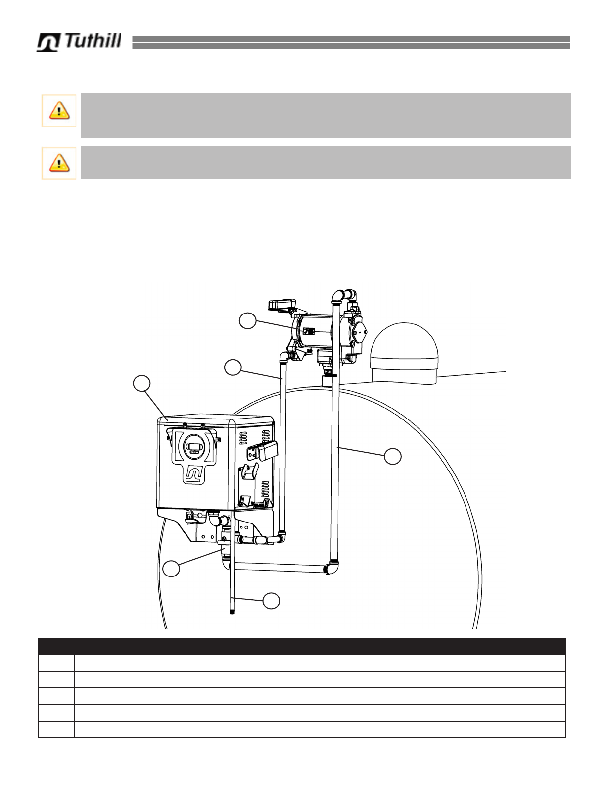
1. Install the pump (if not included) securely to the top of the fuel tank
per the instructions included with the pump.
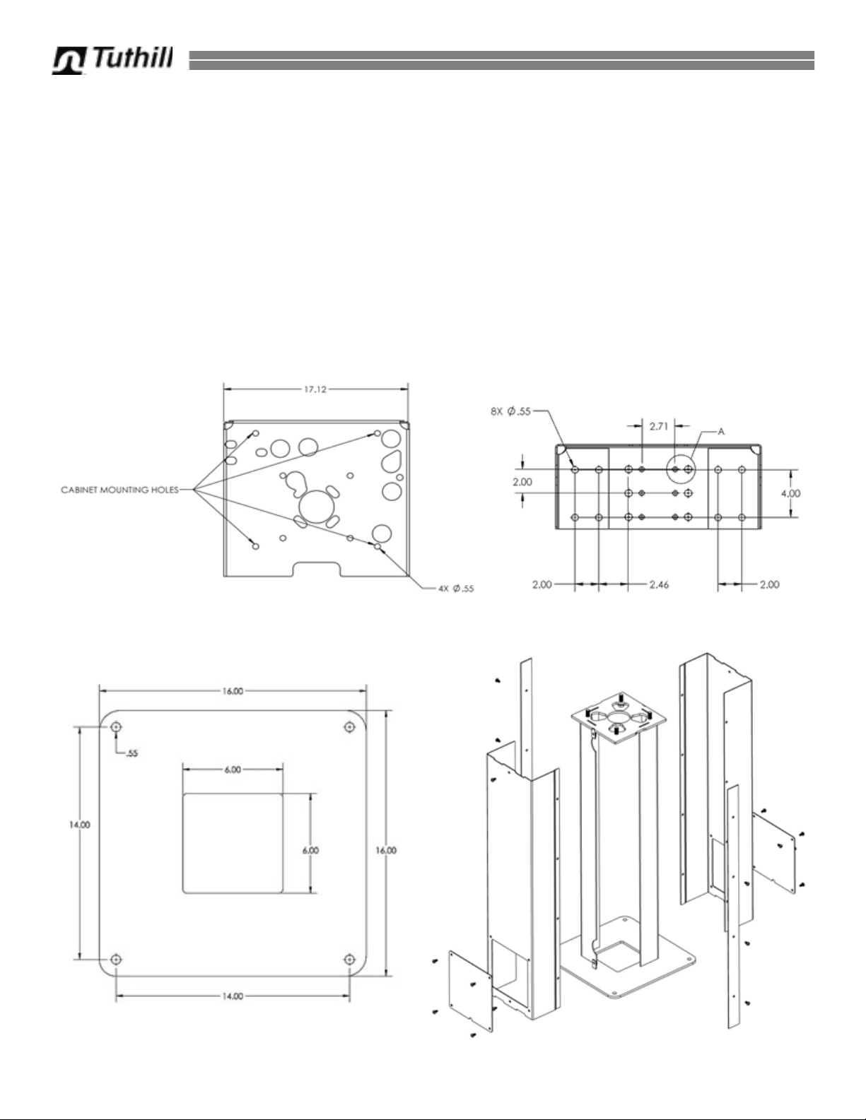
2. Install mounting plate or pedestal as applicable for your installation.
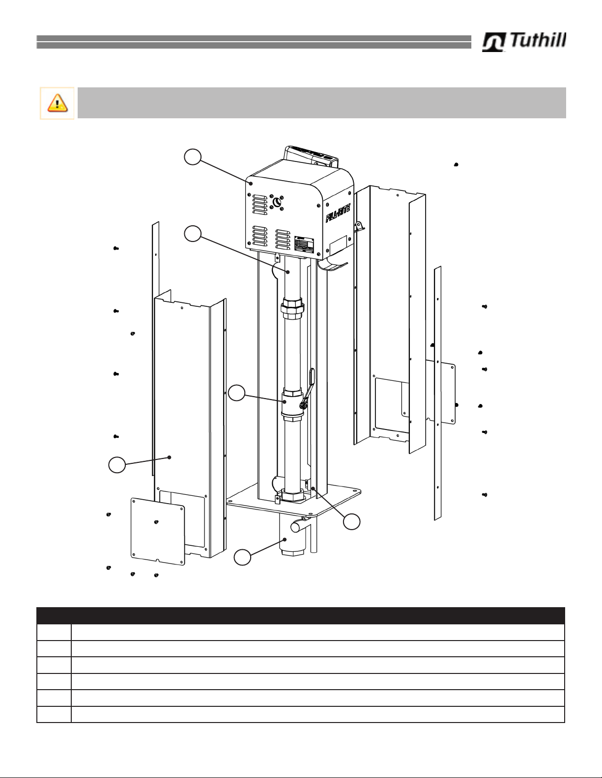
3. Place dispenser on mounting plate or pedestal; using the 4 – 1/2 x
13 screws, and grommet washers, attach the dispenser securely to
the mounting surface through the 4 holes located in bottom of the
dispenser cabinet base (gure 1).
4. Installations must include an Emergency Shut-Off Valve (not
supplied) to the dispenser inlet. Position valve so it can be rigidly
mounted and is not dependent on the dispenser for support.
5. Carefully measure and install pipe between the pump and
Emergency Shut Off Valve. The pipe is not intended to support
the pump or the dispenser in any manner.
NOTE: Dimensional drawings to aid in installation are located on page 4.
CAUTION! Threaded pipe joints and connections should be sealed with the appropriate
sealant or sealant tape to minimize the possibility of leaks.
Electrical Installation
WARNING! Overall dispenser installation and electrical wiring should be performed ONLY
by a licensed electrician and service personnel in compliance with local, state, and national
electrical code NEC/ANSI/NFPA 70, NFPA30, NFPA 30A, and NFPA 395 as appropriate to
the intended use of the dispenser. Threaded rigid conduit, sealed ttings, and conductor seal
should be used. The pump must be properly grounded. Improper installation or use of this
dispenser can result in serious bodily injury, or death!
CAUTION! All electrical appliances should operate at the rated nameplate voltage. Power
should be supplied to this dispenser from a dedicated circuit breaker appropriately sized to
handle the pump being used with the dispenser. No other equipment should be powered
by this circuit. Wiring must be of sufcient size to carry the correct current for the pump.
Voltage drop will vary with distance to pump and size of wire; refer to the National Electrical
Code (NEC), or local codes, for voltage drop compensation to be sure you are using the
correct size wire for your application.
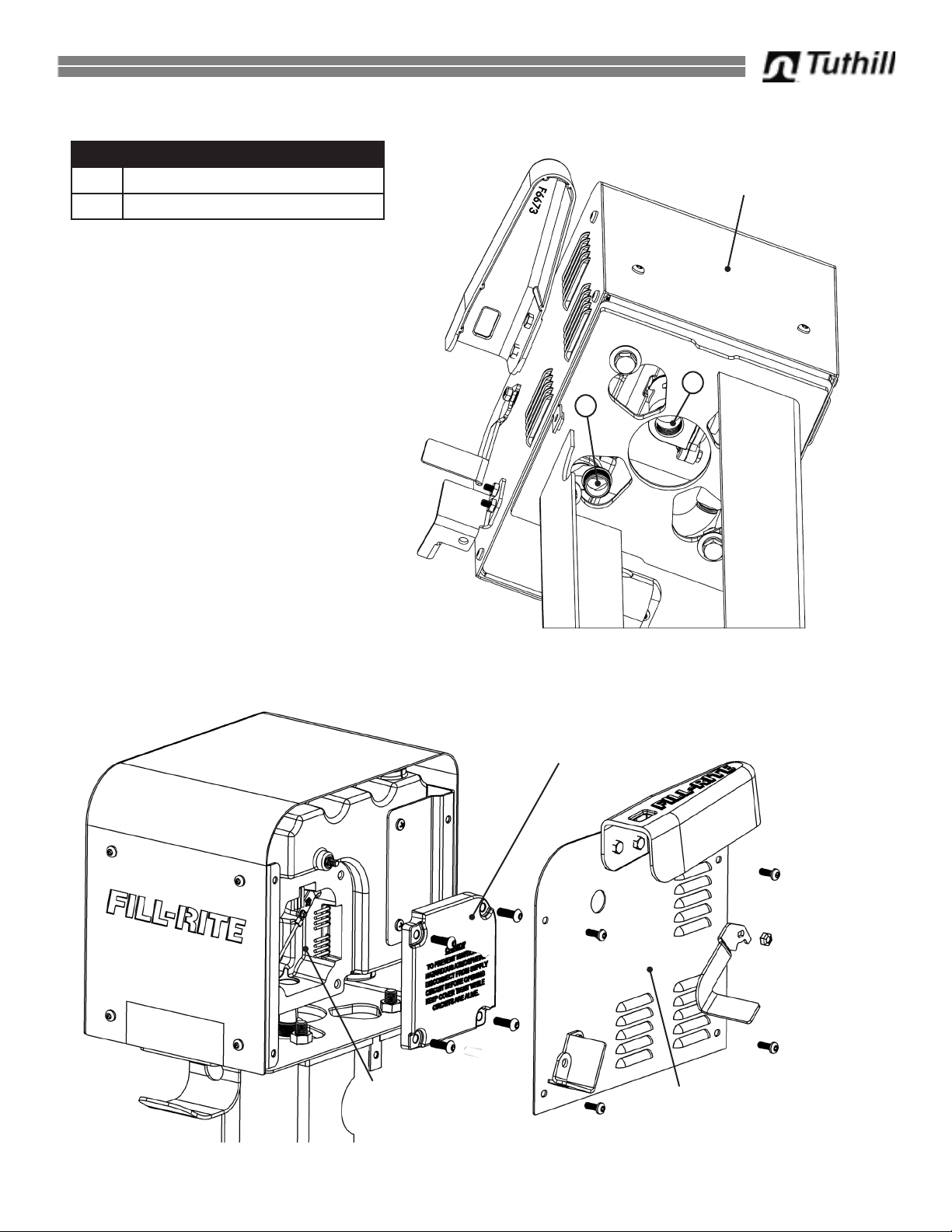
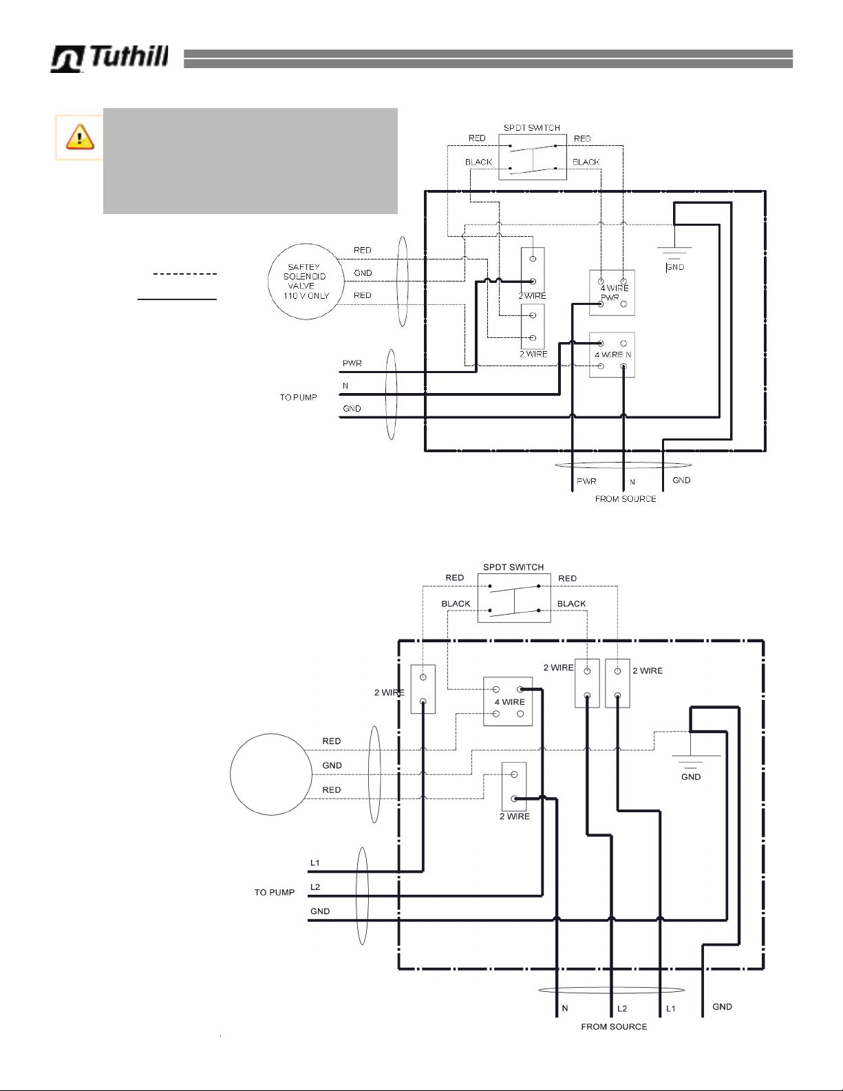
Refer to the section of this manual pertaining to your particular model for detailed wiring information.
All wiring connections must be made inside the explosion proof junction box built into every dispenser
cabinet. Use extreme caution when wiring in this junction box to maintain the integrity of the
explosion proof design. The 300 Series pump inside the FR302DPUU cabinet has a wiring junction
box on the pump for the pump wiring (see diagram page 12 and 13).
5
Figure 1
Cabinet Dispenser Electrical Rating
Model Voltage (VAC) Frequency (Hz) Current (A) Power (HP)
FR102PHU
FR902DPU
125 60 20 1
250 60 20 2
FR302DPU 115/230 60/50 9.8/4.9/11.4/5.7 3/4

Plumbing Installation
IMPORTANT! Remote dispensers and tank top pumps must be installed in accordance with
all local, state, and national electrical code NEC/ANSI/NFPA 70, NFPA 30, NFPA 30A, and
NFPA 395.
Your Fill-Rite dispenser cabinet should be installed in a manner that does not use the plumbing to
support the cabinet in any way. Safety and Emergency equipment should be installed per local,
state, and national plumbing for ammable fuels guidelines. The following plumbing diagrams are
suggestion for typical installation scenarios.
Item Description
1 Remote Pump (for use with FR102PHU, FR902DPU)
2Electrical Conduit (Threaded rigid conduit, sealed ttings, conductor seal)
3 Wall Mounted Cabinet Dispenser (FR902DPU)
4 Fluid Inlet Pipe (Threaded pipe joints and connections should be sealed)
5 Safety Breakaway Valve
1
2
3
4
5
2
CAUTION! Threaded pipe joints and connections should be sealed with the appropriate
sealant or sealant tape to minimize the possibility of leaks.
Typical Wall Bracket Mount Plumbing
6

Typical Pedestal Mount Plumbing
Item Description
1 Remote Dispenser Cabinet (applicable to FR102PHU, FR902DPU)
2 Inlet Pipe
3 Shut-Off Valve
4 Safety Breakaway Valve
5Electrical Conduit (Threaded rigid conduit, sealed ttings, conductor seal)
6Exterior Cover
CAUTION! Threaded pipe joints and connections should be sealed with the appropriate
sealant or sealant tape to minimize the possibility of leaks.
1
2
3
4
5
7
6

8
FR102PHU Information
FR102PHU Internal Components
Item Description
1Explosion Proof Junction Box
2 Solenoid Valve
3 Electrical Conduit
4 Fluid Plumbing
1
4
2
3
3
This section contains the following
information specic to the FR102PHU
Dispenser Cabinet:
• Dimensional Information
• Internal Components
•Installation / Access Information
• Plumbing Information
• Wiring Information
Nozzle Boot
Switch Lever
Nozzle Rest
Hose Hook

9
FR102PHU Junction Box Access
FR102PHU Cabinet Bottom Wiring and Plumbing Entry Points
A
B
Back of Cabinet
Item Description
A Electrical Wiring Conduit
B Plumbing Inlet
View is from below, with cabinet
mounted on pedestal
Explosion proof junction
box wiring cover.
Removable Side Access Panel
Wiring opening in
junction box.

10
FR102PHU 220 VAC Electrical Wiring Diagram
FR102PHU 110 VAC Electrical Wiring Diagram
Factory Wiring
Field Wiring
Safety
Solenoid
Valve
110V Only
CAUTION! Power should be supplied
to this dispenser from a dedicated
circuit breaker appropriately sized to
handle the pump being used with the
dispenser.

11
FR302DPU Information
This section contains the following
information specic to the
FR302DPUU Dispenser Cabinet:
• Dimensional Information
•Installation / Access Information
• Internal Components
• Wiring Information
• Plumbing Information
Nozzle Boot
Switch Lever
Nozzle Rest
Hose Hook
FR302DPU Internal Components
Item Description
1Explosion Proof Junction Box
2 900 Series Digital Meter
3300 Series Pump, 3/4 HP
4 Fluid Plumbing
5Hammer Arrestor
1
4
5
2
3
11

12
FR302DPU Cabinet Bottom Wiring and Plumbing Entry Points
Item Description
A Electrical Wiring Conduit
B Plumbing Inlet
View is from below. Front of cabinet is
at the top of the illustration.
Cabinet Front
B
A
FR302DPU Junction Box Accesses
Barrier Wiring
Motor Wiring

13
Factory Wiring
Field Wiring
FR302DPU 110 VAC Wiring
FR302DPU Motor Wiring (110 VAC and 220 VAC)
NOTE: Only wiring for the
barrier passes through the
Explosion Proof Junction Box
on FR302PH models. Wiring
for the barrier is 110VAC
ONLY! Wiring the barrier
to 220VAC will damage the
barrier and meter!
Wiring for the motor (110 VAC
and 230 VAC) runs through
the junction box on the motor
(see access information on
page 11 and 13).
Voltage Selector
Switch
The 300 series pump located inside the FR302PH
Dispenser Cabinet can be wired to operate on 110 VAC
or 220 VAC. Be certain to set the Voltage Selector Switch
to the correct setting for the input voltage. The Voltage
Selector Switch is located on the end of the pump, just
above the pump wiring junction box (see illustration
below). Power should be supplied by a dedicated 30 amp
breaker.
Motor Wiring

14
FR902DPU Information
This section contains the following
information specic to the FR902DPU
Dispenser Cabinet:
• Dimensional Information
•Installation / Access Information
• Internal Components
• Wiring Information
• Plumbing Information
Nozzle Boot
Switch Lever
Nozzle Rest
Hose Hook
FR902DPU Internal Components
Item Description
1Explosion Proof
Junction Box
2900DP Digital
Meter
3 Wiring Conduit
4 Fluid Plumbing
5Hammer Arrestor
6 Solenoid Valve
1
4
5
2
3
4
6

15
FR902DPU Junction Box Access
A
BC
Item Description
AExplosion Proof Junction Box
B Field Wiring Cover
CExterior Access Panel
FR902DPU Cabinet Bottom Wiring and Plumbing Entry Points
Item Description
A Electrical Wiring Conduit
B Plumbing Inlet
View is from below. Front of cabinet is
at the top of the illustration.
Cabinet Front
BA

16
FR902DPU 110 VAC Electrical Wiring Diagram
FR902DPU 220 VAC Electrical Wiring Diagram
Factory Wiring
Field Wiring
CAUTION! Power
should be supplied to
this dispenser from a
dedicated circuit breaker
appropriately sized to
handle the pump being
used with the dispenser.
DC1404-000 Rev 1

Manual de instalación, funcionamiento y seguridad del propietario
Gabinetes dispensadores remotos
Modelos
FR102PHU
FR302DPU
FR902DPU
Tuthill Corporation 8825 Aviation Drive Ft. Wayne, IN 46809 (260) 747-7529 www.tuthill.com www.llrite.com

Acerca de este manual.......................................................................................................................................2
Información de seguridad.....................................................................................................................................3
Cierre con candado..............................................................................................................................................3
Instalación..............................................................................................................................................3
Instalación mecánica.............................................................................................................................................5
Instalación eléctrica..............................................................................................................................................5
Instalación de plomería........................................................................................................................................6
Instalación de soporte de pared típica................................................................................................................6
Instalaciones de pedestal típicas.........................................................................................................................7
Información especíca de FR102PH.............................................................................................................8-10
Información especíca de FR302DP............................................................................................................11-13
Información especíca de FR902DP............................................................................................................14-16
¡Gracias!
Índice
Gracias por adquirir el gabinete dispensador Fill-Rite®. Su producto Fill-Rite cuenta con más de 80 años
de experiencia en transferencia de líquidos, lo que le brindará valor, junto con un rendimiento superior, un
diseño fácil de usar, una larga vida útil y un diseño de ingeniería simple y resistente. La experiencia que le
proporciona tranquilidad.
Excelencia en el trabajo. Excelencia en la vida.
Acerca de este manual
Desde el concepto y el diseño inicial hasta la producción nal, el dispensador Fill-Rite está fabricado
para brindarle años de servicio sin ningún problema. Para garantizar que proporcione dicho servicio, es
fundamental que lea por completo este manual antes de intentar instalar y operar su nuevo dispensador.
Familiarícese con los términos y diagramas, y preste mucha atención a las áreas destacadas con las
siguientes etiquetas:
¡ADVERTENCIA! Destaca un área en que se pueden producir lesiones corporales e incluso la
muerte si no se siguen las instrucciones de manera adecuada. También se pueden producir daños
mecánicos.
¡IMPORTANTE! Estos cuadros contienen información que ilustra un punto que podría ahorrar
tiempo o ser clave para la operación adecuada, o que clarica un paso.
¡PRECAUCIÓN! No prestar atención al aviso de “Precaución”podría provocar daños al equipo.
En Fill-Rite, su satisfacción con nuestros productos es primordial para nosotros. Si tiene cualquier duda o
necesita asistencia con nuestros productos, comuníquese con nosotros al 1-800-634-2695 (lunes a viernes de
8:00 a. m. a 5:00 p. m., hora del Este).
La información de la garantía de su producto Fill-Rite la puede encontrar en: www.llrite.com
2

Información de seguridad
¡ADVERTENCIA! Para garantizar una operación segura y adecuada de su equipo, es
fundamental leer y cumplir todas las siguientes precauciones y advertencias de seguridad. La
instalación o el uso incorrectos de este producto pueden provocar lesiones graves o la muerte.
1) ¡NUNCA fume cerca del dispensador ni lo utilice cerca de una llama mientras dispense un
líquido inamable! Se puede producir un incendio.
2) En el oricio de salida del dispensador se debe usar un ltro “Fill-Rite”para garantizar que
ningún material extraño se transera al tanque de combustible.
3) Las juntas de tuberías roscadas y las conexiones se deben sellar con un sellador adecuado o
cinta selladora para minimizar las posibilidades de ltraciones.
4) Los tanques de almacenamiento deben estar correctamente anclados para evitar su
desplazamiento o volcamiento cuando estén llenos o vacíos.
5) Para minimizar la acumulación de electricidad estática, utilice solo un tubo exible conductor
de cableado estático cuando dispense líquidos inamables y mantenga la boquilla llena en
contacto con el recipiente que se esté llenando durante el proceso de llenado.
6) NO exceda las 3,5 bar/50 psi de presión en la tubería.
7) NO instale una válvula de contención o una válvula de retención adicional sin una válvula de
alivio de presión, de lo contrario el dispensador podría romperse.
¡ADVERTENCIA! Este producto no se debe utilizar para transferir líquidos a ningún tipo de
aeronave.
¡ADVERTENCIA! Este producto no es apto para su uso con líquidos destinados al consumo
humano o líquidos que contengan agua.
Cierre con candado
Para mayor seguridad, la boquilla de su bomba Fill-Rite se puede
cerrar con un candado. Con la bomba está apagada, y la boquilla
en la posición de almacenamiento, se puede insertar un candado a
través del apoyo de la boquilla y la abertura del mango de la boquilla.
Esta conguración evita que se retire la boquilla y se encienda la
bomba.
Instalación
En la entrada del dispensador se debe instalar una válvula de cierre
de emergencia con eslabón fusible. Todas las tuberías deben ser de
Cédula 40. Use un compuesto para tuberías resistente a la gasolina
y al aceite que esté clasicado en la lista de UL en todas las juntas
roscadas. Consulte las páginas 14 y 15 para obtener los diagramas
de plomería de muestra.
¡IMPORTANTE! Los dispensadores remotos y bombas de montaje sobre el tanque se deben instalar
según los códigos eléctricos locales, estatales y nacionales NEC/ANSI/NFPA 70, NFPA 30, NFPA
30A, y NFPA 395.
3

Adicionalmente, los dispensadores de gabinete Fill-Rite necesitan que se les instale una válvula de alivio de
presión, con certicación de seguridad, ya sea como parte de la bomba o por separado en el dispensador
mismo. Para asegurar una operación adecuada, su gabinete dispensador se debe jar sobre una supercie
de montaje sólida. Fill-Rite recomienda instalar los dispensadores de gabinete, ya sea sobre el juego de
soporte de montaje KITWM o el pedestal KITPD.
Estas dos opciones de montaje están especícamente diseñadas para usarlas con los dispensadores de
gabinete FR302DP, FR902DP y FR910PM de Fill-Rite (el modelo estándar FR102PH viene con el pedestal
KITPD) y cuentan con aberturas taladradas previamente ubicadas para la plomería, el cableado y la sujeción.
También incluyen las piezas metálicas necesarias para sujetar el gabinete de forma correcta y segura en el
lugar. Consulte con su distribuidor Fill-Rite para obtener más información sobre estos juegos de montaje.
Soporte de pared KITWM
Pedestal KITPD
4
435 mm
(17.12")
4X Ø 0,55"
AGUJEROS DE MONTAJE
DEL GABINETE
69 mm
(2,71")
8X Ø 0,55"
51 mm
(2,00")
51 mm
(2,00")
51 mm
(2,00")
102 mm
(4,00")
62 mm
(2,46")
406 mm
(16,00")
406 mm
(16,00")
356 mm
(14,00")
356 mm
(14,00")
152 mm
(6,00")
152 mm
(6,00")
0,55"
This manual suits for next models
2
Table of contents
Languages:
Other Tuthill Dispenser manuals
Popular Dispenser manuals by other brands

Franke
Franke RODAN RODX674B Installation and operating instructions

Hilti
Hilti HDE 500-22 Original Operating Instruction

NORDWEST
NORDWEST PROMAT SD006 user manual

KATRIN
KATRIN 44672 Measurements and installation instructions

SC Johnson Professional
SC Johnson Professional TouchFREE Dispenser installation guide

APW Wyott
APW Wyott CCW MK VII, RCCW MK VII, LCCW MK VII, RLCCW MK... Installation and operating instructions