Remcor SID851A/250S User manual

Operator’sManualMODELS:SID851A/250S
SID851A/250S-B
SID851W/250S
SID851W/250S-B
SID851A/250S-BC
SID851W/250S-BC
208--230/115V,60HZ,1PH
SPIRALICEMAKERâ
DISPENSER
PRINTEDIN U.S.A
âREMCORINC:1995
PartNo.90914
August, 1995
Revision D
THISDOCUMENTCONTAINSIMPORTANTINFORMATION
ThisManualmustbe read and understood beforeinstalling oroperating thisequipment

i90914
TABLEOFCONTENTS
Page
GENERALINFORMATION1..................................................
DESCRIPTION1........................................................
INSTALLATIONINSTRUCTIONS2............................................
UNPACKINGINSTRUCTIONS2..........................................
INSTALLATIONINSTRUCTIONS2........................................
BEVERAGE SYSTEM7..................................................
INSTALLATION7..................................................
START-UP7...........................................................
OPERATINGINSTRUCTIONS10...............................................
MAINTENANCE14...........................................................
REGULARBASIS(ORAS REQUIRED)14..................................
EVERYTHREE MONTHS(ORAS REQUIRED)14...........................
PERIODICALLY(ORAS REQUIRED)14....................................
CLEANINGINSTRUCTIONS14...........................................
ICEMAKERSECTION14............................................
DISPENSERSECTION15...........................................
FOR UNITSWITHBEVERAGE SYSTEM15............................
TROUBLESHOOTING GUIDE17...............................................
MAINTENANCE/ADJUSTMENTPROCEDURES 30...........................
THERMOSTATALTITUDE ADJUSTMENTS30.........................
BINTHERMOSTAT30...............................................
CLEARINGEVAPORATORFREEZE-UP30............................
ICETHICKNESS ADJUSTMENT31...................................
CLEANING/REPLACETHEFILTER31................................
CLEANINGTHECONDENSER31....................................
HARVEST TIME ADJUSTMENT32....................................
MANUALFILLING32................................................
PARTSLIST34..............................................................
LISTOF FIGURES
FIGURE1.ELECTRICALWIRINGINSTALLATIONINSTRUCTIONS3.........
FIGURE2. INSTALLATION DIMENSIONS4................................
FIGURE3.MOUNTINGTEMPLATEMODELSID851/250-B5................
FIGURE4.MOUNTINGTEMPLATEMODELSID851/250-BC6...............
FIGURE5.BEVERAGE SYSTEMSCHEMATICBMODELS8................
FIGURE6.BEVERAGE SYSTEMSCHEMATIC-BCMODELS9..............
FIGURE7.WIRINGSCHEMATICSID850/250 11............................
FIGURE8.WIRINGDIAGRAMSID850/250 (208--230/115V,1PH,60HZ)12.....
FIGURE9.REFRIGERATIONSCHEMATIC13...............................
FIGURE10.HARVEST TIMER33..........................................

ii
90914
TABLEOFCONTENTS(cont’d)
LISTOF TABLES
Page
TABLE1.SPECIFICATIONS1............................................
TABLE2.LBS./24-HOUR ICE PRODUCTION1.............................
TABLE3.HARVESTCYCLE1............................................

190914
GENERALINFORMATION
DESCRIPTION
The RemcorS.I.D.(SpiralIceMaker/Dispenser) isa unique,self-contained,countertop style unit thatautomati-
callymakeshard,clearcube-qualityice and storesitinasealed hopperforsanitarydispensing.The iceis
made bya new,patented process onaspiral-shaped,stainless steelevaporatorand producestrue cube quality
iceonthe outside of the tubes.There are no augers;no compressing of flaked ice;no bearings;and no high
gearmotorloadsinthe ice-making process.The unithasbeen designed tobesimple,yeteffective, to provide
many yearsof trouble-free operation.
Table 1.SPECIFICATIONS
Compressor:1Horsepower
Refrigerant: R-502/2.25 lbs.(AirCooled);2.75 lbs.(WaterCooled)
Voltage:208-230/115,1 phase,60 Hertz
AMPS:18
CircuitAmpacity:25
FuseSize:20ATime-Delay
IceStorage Capacity:225 lbs.
IceMaking Capacity:Upto 964 lbs./24 Hours
Shipping Weight: 550 lbs.
Table 2.LBS./24-HOUR ICE PRODUCTION
AirTemp.WaterTemperature
40°50°60°70°80°90°
60°964 901 861 806 755 712
70°916 858 820 777 728 687
80°817 756 731 700 656 619
90°725 680 650 630 590 556

290914
INSTALLATIONINSTRUCTIONS
UNPACKINGINSTRUCTIONS
1.Withthe unitupright, carefullyremovethe shipping crate. Inspect forshipping damage and reportany such
damage tothe shipperimmediately.
2.Open the hinged service doorand removeshipping tape fromthe ice drop cover,storage hoppercoverand
agitatorinthe storage hopper.
3.Removeshipping tape fromairinlet filterand sinkgrill.
INSTALLATION
NOTE:AnEverpureModel9320-42 SystemsIV,ModelB1000 (orequal)ice makerqualitywater
treatmentunitMUSTBEINSTALLEDinthewatersupplylinetotheice maker.Failuretodoso
may resultin poorqualityice, lowproduction output,and may cause prematurefailureof the
ice makerevaporatorand voidthe extendedevaporatorwarranty.
Thisicemakerisprovided withastainless steelevaporatordesigned tolast the life of the product. But, some of
the chemicalsintreated and untreated water,specifically chlorine and sulphur (sulphide),havethe abilityto at-
tachstainless steeland cause prematurefailure.Aninitial investmentin properwatertreatmentwill payforitself
inincreased production,qualityand long life of the product.
1.Location
Locatethe icemaker/dispenserindoorsinawell-ventilated area.Avoid exposureto directsunlightand/or
heatcaused byradiation.
Ambientroomtemperaturemustbe inthe range of60°to 90°F.Do notinstall unitin an enclosed area
where heatbuildupcouldbeaproblem.Forproperairflowforthe refrigeration system,allowa 6? clear-
ance at the back of the unitand a 12? clearance at the rightside panel.
ConsultFigure1forutility connection location.
ConsultFigure2fordimensionsformounting unit tothe counterwiththe hardware provide.Notethat the
unitmustbelevelforproperoperation.
The unitmustbe sealed tothe counter.The mounting template drawing (Figure 2)indicated the openings
whichmustbe cutinthe counter.Locatethe desired position forthe unit, then markthe outline dimensions
and cut-outlocationsusing the template drawing.Cutopeningsincounter.
Applyacontinuousbead ofNSFInternational(NSF)listed silastic sealant(Dow732 orequal)approximate-
ly1/4? inside of the unitoutline dimensionsand around all openings.Then position the uniton the counter
withinthe outline dimensions.All excess sealantmustbe wiped away.
2.Plumbing
Connect the icemakerto a cold,potablewatersourcesuitablefordrinking.Do notinstall unitonawater
softenerline.Itisrecommended thata hand shut-off valve,strainer,and backflowpreventerbe used on the
incoming supplyline.ForModels:SID851/250Sand SID851/250S-B,a 3/8? outside diametercompression
tube fitting isprovided at the back of the unit forthe watersupplyhookup (See Figure 1).Formodel
SID851/250S-BC,a 3/8? beverage tubing witha3/8x1/4 barbsplicerfitting isprovided forconnection
through the bottomopening inthe unit tothe watersupply(See Figure 2).

390914
IMPORTANT:To ensureproperice makeroperation and alsotoreduce thefrequency ofwater-related
service problems,awaterfiltershould beinstalled.Remcor recommendstheuse ofoneof the
following basic systems:
1.Everpure, Inc.2.SystemIV
660 No.BlackhawkDrive 16632 Burke Lane
Westmont, IL 60559 Huntington Beach,CA92647
(708)654-4000 (714)842-4221
InsurlceTwinSystem#9320-42 BasicWaterSystem#B1000
Forspecificrecommendationson thesefiltersystemsforyourlocalconditions,consultwithadistributorinyour
area orcontact the filtermanufacturer.
ModelsSID851/250S&SID851/250S-B
Connect two(2)3/4? IPS (orequal)drainlinestothe 3/4? threaded drainconnectionsat the lower rearof the
unit. Theselinesmustpitch downwardto an open drain and mustcontainnotrapsorimproperdrainage will
result.
ModelSID851/250S-BC
A1? ODtubing drain elbowisprovided at the bottomof the unit forthe sinkdrain.Connect thiselbowtoa7/8?
IDplasticdraintube.
A3/4? IPS threaded drainconnection forthe icemakerisalso provided at the bottomof the unit. Connect this
toa3/4? IPS drainline (orequal).
Theselinesmustpitch downwardto an open drain and mustcontainnotrapsorimproperdrainage will result.
NOTE:Inareas where consistentlywarmwatertemperatures are encountered,theuse ofaRemcorPre-
Coolerinthewaterlineisrecommendedtomaximizetheice production of thisunit.ContactRemcor
formoreinformation on thisproduct.
2.Electrical
A4x2junction boxislocated at the rearof the unit forthe supplyhook-up.Connect the icemakertoits
owncircuitperthe nationalelectric code and localcode.See SPECIFICATIONSforampacityand fuse
size.
IMPORTANT:Thewire sizemustbe adequateforthe ampacityrating,and the supply voltagemustbe
withinarangeof±10%forproperice makeroperation.
NOTE:Theunitsrequirea3wire systemplus earth ground forproperoperations.
FIGURE1.ELECTRICALWIRINGINSTALLATIONINSTRUCTIONS
115/208-230V
1PHASE
60 HERTZ
SUPPLYCONDUIT
BLACK (HOT)
RED(HOT)
WHITE(NEUTRAL)
GREEN(GROUND)

490914
60
45 7/8
45 1/8
13 1/4
16 1/4
2 1/4 14
8 15/16 2 1/2
20 1/2
1
24 2 1/2
29
1 1/2
AIR DISCHARGE GRILL
CONDENSER WATER OUT
3/8-NPT (WATER COOLED ONLY)
CONDENSER WATER IN
3/8-NPT (WATER COOLED ONLY)
ACCESS PANEL FOR SERVICE
ELECTRICAL INPUT
ACCESS PANEL FOR SERVICE
AND BEVERAGE HOOK-UP
ACCESS PANEL FOR SERVICE
*3/4-FPT DRAIN (2)
*ICEMAKER WATER IN
3/8 O.D. TUBE COMP. FITTING
*FOR MODELS:
SID 851/250
SID 851/250-B
3212 12
16
22 1/16
12 13/16
3 1/2
9 1/2
FOR BC MODELS:
ACCESS PANEL FOR BEVERAGE
AND UTILITY HOOK-UP
14 1/2 8 1/16
33 1/16 32 1/8
6
12
15 1/8
25 3/8
18 3/4
36
9 3/4
CLEARANCE NECESSARY ONLY
IF UNITS ARE INSTALLED IN AN
ENCLOSED SPACE.
DOOR WITH LOCK FOR ACCESS
TO ICE STORAGE AREA.
FIGURE 2. INSTALLATION DIMENSIONS

590914
15 7/8-IN.14-IN.
2 3/4-IN.
10 1/2-IN.
16-IN.
32 1/2-IN.
36-IN.
27 11/16-IN.
32-IN.
2 1/8-IN.UNITOUTLINEFRONT
3/8DIA.
NOTE:Shadedarea indicates opening in
bottomforbeveragetubing.
FIGURE3.MOUNTINGTEMPLATEMODELSID851/250-B

690914
27 11/16-IN.3 1/16-IN.
32-IN.
14 1/8-IN.
11 1/4-IN.
36-IN.
10 1/2-IN.
16-IN.19 5/8-IN.5 7/8-IN.
1/2DIA.
NOTE:Shadedarea indicates opening in
bottomforbeveragetubing and utilities.
FRONT
UNITOUTLINE
FIGURE4.MOUNTINGTEMPLATEMODELSID851/250-BC

790914
BEVERAGE SYSTEM
“B”models contain beverage faucetsonlyand mustbe supplied withcold product fromanyremotecold plate or
refrigerated soda factory.“BC”unitshave a built-incold plate,in addition tothe beverage faucetsand are de-
signed tobesupplied directlyfromsyrup tanks and carbonatorwith no additionalcooling required.
Installation
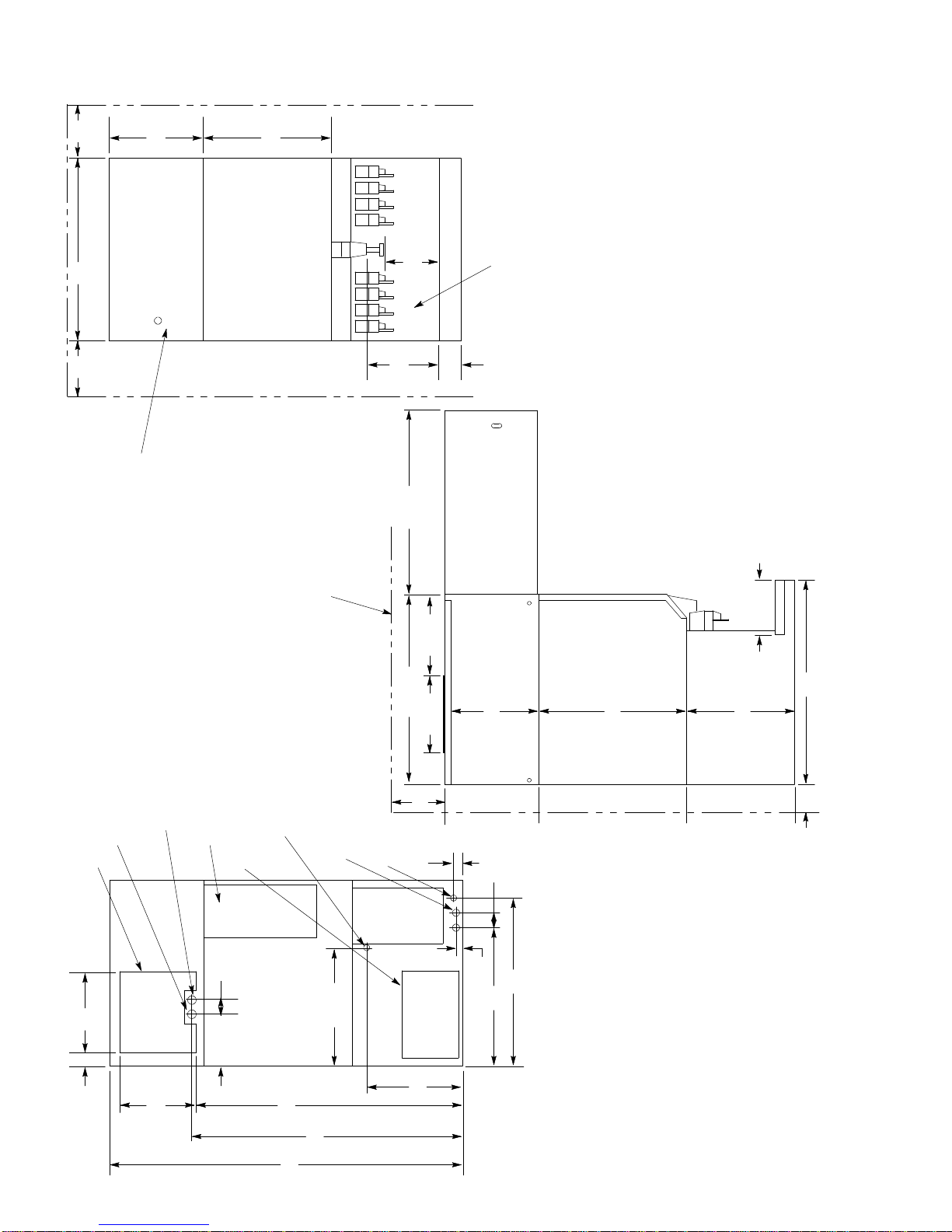
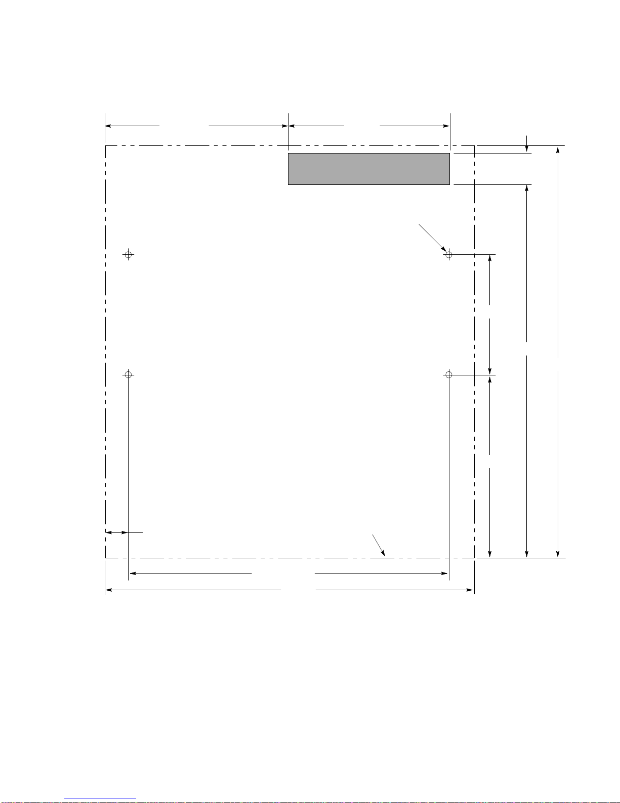
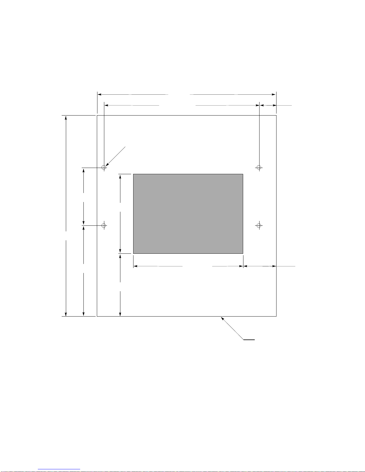
1.Locatethe required openingsinthe countertop forthe beverage linesas showninFigure3(for“B”mod-
els)orFigure4(for“BC”models).
2.For“B”models,carefullypull the beverage tubersthrough the bottomopening inthe unitand through the
clearance opening inthe counter.
3.For“BC”models,1/4? and 3/8? beverage tubing “pigtails”are provided at the frontof the uniton the cold
plateforsyrup and waterline hook-up respectively.
To access theseinlet tubes,removethe lowerfrontpanelabovethe sink.Removethe sinkbydisconnect-
ing the sinkdrainconnection;lifting the two(2)sink side mounting pinsand pulling the sinkforward.
4.Connect the beverage systemproductlinesasindicated inFigure5(“B”units)and Figure6(“BC”units).
Thiswork should be done bya qualified service person.Notethat the hosesaremarked with numbers
(1through 8)forsyrup connection and “CW”forcarbonated waterconnection.
5.For“BC”models,reversethe procedureinstep3toreconnect the sink.Makesurethatall drainconnec-
tionsare properlypositioned beforeinstalling the lowerfrontpanel.
START-UP
1.Open the hinged service door.Removeice drop coverand storage hoppercover.
2.Turnonwatertoicemaker.
3.Depress the flushswitchtoverifythat the waterdumpvalve operatesand that the waterdrainlinesare
open and notplugged.
WARNING:To preventpossibleinjury,do notstick fingersorhand intoice makernozzleor
hopperwith powerappliedto unit.
4.Put the “Stop/Run”switchinthe “run”position.Observethat the icemakergoesthrough propericemaking
and harvestcycles.Ifunitmalfunctions,consult the Troubleshooting Guide.
NOTE:Duetomeltageloss because ofawarmstoragehopper, itwill take longertofill thehopperthe
first timethanwhentheice makerhas been operating continuously.
5.Depress the vend switchlever.Check thatboththe gatesolenoid and agitatormotorare energized simulta-
neouslytolift the gateslide and rotatethe agitatorinthe storage hopper,respectively.Ifeithercomponent
malfunctions,consult the Troubleshooting Guide.Replacethe ice drop and hoppercovers.
6.Forbeverage units,startup the beverage systemand adjust the faucetstothe properbrix.Contactyour
localsyrup distributorforcompleteinformation on the beverage system.Forunitswith a builtincold plate,
itwill take approximatelyone (1)hourfromthe initialmachine start-up forthe cold plateto be at full capac-
ity.
7.The binthermostatis calibrated atan atmosphericpressure equivalentat500 feetabovesea level.For
locationsathigherelevations,itmaybe necessarytore-adjust thesecontrols.Consult the Maintenance/
AdjustmentProcedures section.

8
90914
1
2
3
4
5
6
7
8
8 7 6 5 4 3 2 1
COLD PLATE
PRIMARY REGULATORS
OPTIONAL FOR
DIET OR
ROOT BEER
CARBONATOR FILTER
OPTIONAL
PRESSURE
REGULATOR
WATER
SUPPLY
CO2TANK
15-50 PSIG
60-100 PSIG
NON-CARB OR
CARB WATER
LINE LEGEND
CO2
CARB WATER
PLAIN WATER
SYRUP
OPTIONAL
ITEMS OUTSIDE OF
BROKEN LINE ARE NOT
INCLUDED WITH UNIT
FIGURE 5. BEVERAGE SYSTEM SCHEMATIC B MODELS

990914
FIGURE 6. BEVERAGE SYSTEM SCHEMATIC -BC MODELS
1
2
3
4
5
6
7
8
8 7 6 5 4 3 2 1
COLD PLATE
PRIMARY REGULATORS
OPTIONAL FOR
DIET OR
ROOT BEER
CARBONATOR FILTER
OPTIONAL
PRESSURE
REGULATOR
WATER
SUPPLY
CO2TANK
15-50 PSIG
60-100 PSIG
NON-CARB OR
CARB WATER
LINE LEGEND
CO2
CARB WATER
PLAIN WATER
SYRUP
OPTIONAL
2
3
4
1,5,6,
7,8
ITEMS OUTSIDE OF BROKEN LINE
ARE NOT INCLUDED WITH UNIT.

1090914
OPERATINGINSTRUCTIONS
Atemperaturesensing controlbulblocated inthe storage hopperstartsand stopsthe icemaking process in
responsetoicelevel inthe hopper.Withthisicelevelcontrol“calling”forice(hoppericelevel islow),ice begins
toformon the stainless steeltubing coilsinthe evaporatorcoilsuntil itcontactsthe icethickness probe (low
voltage conductivity sensor).At thispoint, the conductivityprobe triggersthe harvest timermotor.The harvest
timercontainsfive(5)camoperated switcheswhichfunction asdetailed inthe tableonthe following pages.
Table 3.HARVESTCYCLE
TimeCamSwitchAction
0--86 Seconds#1 Timermotorenergized
1--23 Seconds±1Second #4 Waterdumpvalve open
1--37 Seconds±2Seconds#2 Hotgas solenoidvalve open.
Airpump off.
Condenserfan motoroff.
37--90 Seconds#2 Airpump on.
Condenserfan motoron.
Hotgas solenoidvalveclosed.
36--39 Seconds#3 Harvestmotoron.
43--47 Seconds#5 Hopperagitatormotoroperates.
When icecontactsthe icelevercontrolbulbinthe storage hopper, the controlwill shutdownthe refrigeration
system. If this signaloccursduring the harvestcycle, the harvestcyclewill be completed beforeshutdown oc-
curs.
To dispenseice,pushthe leverlocated on the lowerfrontpanel. Icewill flowfromthe icechute until the leveris
released.
Forunitswith a built-incold plate,icewill automaticallyfill the cold platecabinet. Allowone (1)hourforthe cold
platetoreachitsmaximumcapacity.Startup the beverage systemand adjust the faucetstothe properbrix.
Pushing the leveron anyfaucetwill provide beverage of the appropriateflow.

11 90914
L1
CC
TP
5
208-230 /115V,1PH,
(4WIRE SYSTEM)
COMPRESSOR
C
2
START
RELAYSTARTCAP
STOP/
RUN LPS HPS BINT’STAT
RUN CAP
5CC
L2N
COMPRESSOR
CONTRACTOR
HARVESTMOTOR
CC
RED
BLUE
CAP
CONDENSERFAN
AIRPUMP
1 2
NC
CHT3
NO
NC
HGSOLVALVE
WATER DUMP VALVE
RUN
CLEAN
FLUSH
HT2
NO
C
NC
HT4
NO
C
WATERLEVEL
PROBE
ICETHICKNESS
PROBEHI
LO
COMCONDUCTIVITY
CONTROL
NC
C
C NC
NO
NO
NO
NC
HT1
LN
WATERFILL VALVE
FILL
CHTHARVEST
TIMER
VEND SWITCH
AR
MOTOR HEATER
NO
HT5C
NC
AGITATOR
RELAY
AR
GATE SOLENOID
AGITATORMOTOR
F
BEVERAGETRANSFORMER(OPTIONAL)
24 VTOBEVERAGEFAUCETS
R
R
FIGURE7.WIRINGSCHEMATICSID850/250

1290914
YELBRN
PUR BLK
R
E
D
O
R
N
RED
BRN
YEL
R
E
D
RED
YEL
BLUELPS
FUSE 1-1/4AMP
TIMEDELAY
AGITATOR
MOTOR CAP
CLEAN
ICEMAKER
RUN
RUN
STOP
PUSHTO
FLUSH
BRN
BLK
Y
E
L
BLK
BLK
FILL
VALVE
RED
O
R
N
PUR
MANUAL
WATER
FILL
BIN
T’STAT
PINK
BLK
PINK
BLK
RED
O
R
N
BLK
BLUE
ORANGE
HPS
ORN
RED
W
H
T
RED
WHT
B
L
K
Y
E
L
GATE
SOLENOID
VOID
SWITCH
BLUE
P
I
N
K
NEUTRAL
TERMINALBOARD
MORELOCATIONMAY VARY
W
H
T
HARVEST
TIME
WHT
WHT
CONDUCTIVITY
CONTROL
PINK
WATER
INDICATOR
WHT
L1L2
HILOCOM
Y
E
L
R
E
D
BRN
BRN
BLK
BLK
W
H
T
COMPRESSOR CONTACTOR
R
E
D
B
R
N
Y
E
L
W
H
T
WHT
BLK
B
L
K
BLK
WHT
WHT
WHTW
H
T
BRN
TERMINAL
BOARD
115 VOLT
NEUTRAL
YEL
Y
E
L
Y
E
L
Y
E
L
GRN
COMP.
RUN
CAP.YEL
BLK
WHT
RED
RED
COMPRESSOR
STARTCAP.B
L
U
E
GRN
Y
E
L
MERCURY
RELAY
WHT
GRN
RED
BRN
START
RELAY
3
2
1
BLK
BLKBLK
BLK
BLK
WHT
WHT
RED
RED
BLUE
HARVEST
MOTOR CAP.
BLUE
WHT
HQSOLVALVE
WHT
YEL
PINK
WATERLEVELPROBE
WATERFILL VALVE
ICETHICKNESS PROBE
ORN
WHT
BLK
RED
BLUE
RED
ORN
BRN SC
R
BLK
HARVESTMOTOR
COMPRESSORMOTOR
BLK
BLK
CONDENSERFAN MOTOR
AIRPUMP
BLK
RED
GRN
208--230V/115V1PH,60HZ,20AMP
FIELDSUPPLIED
REAR JUNCTION
BOX POWERIN
NO
L2
L1
B
L
K
MOTOR
HEATER
WHT
B
L
K
W
H
T
AGITATOR
MOTOR
BEVERAGE
TRANSFORMER
(OPTIONAL)
WHT
BRN WATER DUMP VALVE
FIGURE8.WIRINGDIAGRAMSID850/250 (208--230/115V,1PH,60HZ)

13 90914
FIGURE9.REFRIGERATIONSCHEMATIC

1490914
MAINTENANCE
REGULAR BASIS(orasrequired)
Cleaning of the icemakerisrecommended on a regularbasisnotonlyforsanitaryreasons,butalsotomaintain
the performance of the unit. Build-up oflime and scalecan hindericemaking production ratesand interferewith
properdispensing of the ice.See Cleaning Instructionsforthe recommended procedure.
EVERYTHREE MONTHS(orasrequired)
It isrecommended that the airinlet filterbe cleaned everythree (3)monthsorsoonerdepending on the operat-
ing environment forproper refrigeration systemperformance.On an air-cooled unit, alsocheck that the con-
denserisfree ofdirt/foreign materialthatcouldcause airflowblockage.Consult the Maintenance/Adjustment
Procedures section forcleaning theseitems.
PERIODICALLY(orasrequired)
Check the vending area sinkforproperwaterdrainage.Remove anyforeign materialfromthe sinkto prevent
drain blockage.
CLEANINGINSTRUCTIONS
IMPORTANT:Theice makershould be cleanedataminimumof three (3)monthintervalsormore
frequently,depending on localwaterconditions.The storagehopperinteriorshould be cleaned once a
month.
CAUTION:Do notuse metalscrapers,sharp objectsorabrasives on the surface of the
storagehopper,as damagemay result.Do notuse solventsorothercleaning agents,as
they may attack theplastic surface.Use onlytherecommendedchemicals and solutionsfor
boththeice makerand hopper.
Ice MakerSection
1.Open the hinged service door.
2.Put the “Stop/Run”switchinthe “stop”position at the end of the harvestcycle.
WARNING:Theunitis still pluggedintothe electricalpowerduring ice makersection
cleaning.Therefore,do notreachinto hopper,and do notcontactexposedelectricalwiring
orcomponents.
3.Removethe ice drop coverfromthe evaporatorand the storage hoppercover.
4.Sealthe evaporatoroutletwiththe plasticplug provided withthe unitand replacethe ice drop cover.
5.Removecleaning fill plug and add four (4)ouncesofVirginiaIceMachine Cleanertothe evaporatorand
replacecleaning fill plug.
CAUTION:VirginiaIce MachineCleanerisamildacid,therefore,normalcare should be
takenwhen using.Keep outofeyes and cuts.Readwarningson packagebeforeusing.Do
notoperateunitinthe cleaning modewithout theice drop coverin place.Theremay be
someoverflowofcleaning solution through the evaporatorvent tubeduring the cleaning cycle.

15 90914
6.Pushmanualwaterfill switch and fill evaporatorwithwater (approximately5seconds).
7.Put the “Clean/Run”switchinthe “clean”position.Allowunit torun inthe cleaning mode foratleast30
minutes.
8.Put the “Clean/Run”switchinthe “run”position.
9.Depress the “Flush”switch push button and drain evaporatorforabout1-1/2minutes.Release push but-
ton.Pushmanualwaterfill switch and allowevaporatortorefill withwater.RepeatStep9three (3)timesto
thoroughlyremovecleaning solution fromevaporator.
10.Depress the “Flush”switch push button for1-1/2minutesto drainthe evaporator.
11.Removethe evaporatorplug.
12.Put the “Stop/Run”switchinthe “run”position and allowunit torun through atleast three (3)completeice
making cyclesoruntil iceisfree of“sweet”taste.
WARNING:Ifunit failsto harvestice,put the“Stop/Run”switchinthe“stop”position.
Depress the“Flush”switch push button for1-1/2minutes to drainthe evaporator.Flush
the evaporatorwith hotwatertothoroughlymeltall theice inthe evaporator.RepeatStep9
toremove all traces of the cleaning solution fromthe evaporator.
13.Dispense all ice outofstorage hopperand discard.
DispenserSection
1.Turn off main electricalpowersupplytomachine.
2.Remove agitatorassemblyfromstorage hopperand wash and rinseit thoroughly.
3.Wash down all inside surfacesof the icestorage area,including the top coverand ice drop coverwith a
mild detergentsolution and rinsethoroughlytoremove all tracesofdetergent.
4.Replace agitator.
5.Removeicechutecoverasfollows:
A.Flex sidesoutwardto disengage lowerpins.
B.Lift icechutecoverto disengage upperpins.
C.Lowericechutecoverdown outofunit. Note:Itmay behelpfultotwistcoverslightly.
6.Clean the inside of the icechute and icechutecoverwithamild detergentsolution.Rinsethoroughlyto
remove all tracesofdetergent.
7.Reversestepsabovetoreassembleicechute.
8.Sanitizethe inside of the hopperagitator,icechute, the hoppercoverand ice drop coverwithasolution of
1 ounce ofhousehold bleachto 2 gallonsofwater.(200 PPM)
9.Replacethe hoppercoverand ice drop cover.Turnonthe electricalpowersupply.The icemakerisready
fornormaloperation.
ForUnitsWithBeverage System
ColdPlate
1.Carefullyremovethe lowerfrontpanel.(Belowbeverage faucets).

1690914
2.Slide the cold platecoverback.(Removeshipping tape and discard).
3.Remove anydebrisfromthe draintrough and spring.Check thatdrain holeisnotclogged.
4.Wash downthe inside of the cold platewithamild detergentsolution and rinse.Asmall,long handled
brushwill be found helpful inreaching the corners.
5.Slide the coverforward, taking carethatitis securelypositioned on the cold plate.
6.Replacethe lowerfrontpanel.
Beverage System
1.Removethe faucetspouts,washinmild detergent, rinse and replace.
2.Disconnectelectricalpowertothe carbonator.Shutoff the watersupplyand closethe CO2regulatortothe
carbonator.
3.Disconnect the syrup tanks fromthe system.
4.Energizethe beverage faucetsto purge the remaining soda waterinthe system.
5.Useaclean 5 gallon tankforeach of the following:
Cleaning Tank:Fill with hot(120°-140°F)potablewater.
Sanitizing Tank:Fill withachlorine sanitizing solution inthe strength of1 ounce ofhousehold bleach(so-
diumhypochlorite)to 2 gallonsofcold(ambient)potablewater (200 PPM).
6.Repeat the following procedure on each of the units’ syrup productlines:
A.Connect the cleaning tanktothe syrup line tobesanitized and tothe CO2system.
B.Energizethe beverage faucetuntil the liquid dispensed isfree ofany syrup.
C.Disconnect the cleaning tankand hookup the sanitizing tanktothe syrup line and CO2system.
D.Energizethe beverage faucetuntil the chlorine sanitizing solution isdispensed through the faucet.
Flush atleast2cupsofliquidto ensurethat the sanitizing solution hasfilled the entirelength of the
syrup lines.Allowthe sanitizertoremaininthe line fortwenty(20)minutes.
E.Disconnect the sanitizing tank.Hookup the product tanktothe syrup line and tothe CO2system.
F.Energizethe faucet toflushthe sanitizing solution fromthe syrup line and faucet. Continue to drawon
the faucetuntil only syrup isdispensed.
7.RepeatStep2inreverse ordertoturnonthe carbonator.Dispense atleast1cup ofbeverage fromeach
faucet. Check taste.Continue toflushifneeded, to obtainasatisfactorytasting drink.

17 90914
TROUBLESHOOTING GUIDE
The following pages containtroubleshooting chartsdesigned to aid an experienced service person in diagnosing
anyoperating problemwhichmaybe experienced.Itisassumed thatnormalservicetechniquesand skillsare
familiartothe person doing the troubleshooting. In orderto gainmaximumbenefit fromthesechartsplease
note:
1.Startat the beginning of the chartand supplythe appropriate answerto each question.
2.Do notskip any section,unless instructed todoso.You mightmiss the solution toyourproblem.
3.Evaluatethe possible problemcausesinthe sequenceinwhichtheyare presented. In general, theybegin
withthe mostlikely(oreasiest)tocheck and proceed tothe less likely(ormorecomplicated).
4. If afterchecking all indicated causes, the problemisnotresolved,itisrecommended thatyou
re-tryasecond time,carefullyevaluating the symptomsand modifying youranswersasnecessary.
5. If you are unabletoresolveaproblemafterseveralattempts,contactRemcorCustomerService
forassistance.
This manual suits for next models
5
Table of contents
Other Remcor Dispenser manuals
Popular Dispenser manuals by other brands

Vinotemp
Vinotemp VT-PRWINEDIS4S owner's manual

Cornelius
Cornelius Enduro/Duraflex Stand 175 Specification sheet

rosseto
rosseto EZ-PRO T3 EZ51377 quick start guide

Andis
Andis LM1 Use & care instructions

Larson Electronics
Larson Electronics XLE-MD-DF-AD-HS-BP instruction manual

Bras
Bras ATLAS UL Operator's manual

U.S. Solid
U.S. Solid USS-LD00014-120MM quick start guide

APW Wyott
APW Wyott HML2-10 Installation and operating instructions

KWC
KWC RODAN RODX600ME Installation and operating instructions

BIELMEIER
BIELMEIER BHG 401 instruction manual

Rubbermaid
Rubbermaid CrackleClean 2158424 manual

Ice-O-Matic
Ice-O-Matic Hotel Dispenser CD 40022 Specifications