Rena Systems TB-390 User manual

TB-390
Conveyor Stacker
OPERATIONS MANUAL
Revised: 7-30-14

TB-390 Operations Rev. 7/30/2014
1
RENA Systems Inc. would like to Thank You for investing in our quality built
products.
Please record the following information for future reference:
Model:
Serial Number:
Purchase Date:
Purchased From:
Dealer Name:
Contact Name:
Address:
Address:
Phone Number:
Please take this opportunity to register your product.
Use the following “Warranty Registration” link to register your product with Rena Systems.
http://www.renausa.com/support_warranty_registration.html

TB-390 Operations Rev. 7/30/2014
2
INTRODUCTION
The TB-390 conveyor is used to transport media away from the exit end of a printer or tabber
and deposit/stack the media into a drop-tray or against an optional back-stop. The stacked media
can then be removed, from the back-stop or drop catch tray, without the need to stop the printer
or tabber.
An optional dryer and dryer mounting kit can also be installed on the TB-390 conveyor to aid in
drying the images applied by an inkjet printer. See the section titled “Optional Accessories”.
SPECIFICATIONS*
Power Requirements
Optional 230V Model
115 VAC, 50/60 Hz, 1.0 AMP
-9.0 AMP with 115V, 700W dryer option
230 VAC, 50/60 Hz, 1.0 AMP
-5.5 AMP with 230V, 700W, dryer option
Motor Circuit Breaker
Fuses:
1 AMP
0.5 AMP x2, 250V, slow blow
- for speed control board.
NOTE: Dryer outlet is NOT fused within
conveyor. Dyer fuses are located on the
optional dryer.
Speed Of Belts:
25 to 250 feet per minute (variable)
-min and max speeds are approximate and can
vary between conveyors.
Dimensions:
Width: 15 in. (38.1 cm)
Length: 34.5 in. (87.6 cm)
Height: 5 in. (12.7 cm, from table top)
Weight: 33 pounds (15 kg)
* MANUFACTURER RESERVES THE RIGHT TO CHANGE SPECIFICATIONS WITHOUT WRITTEN NOTICE.

TB-390 Operations Rev. 7/30/2014
3
SAFETY PRECAUTIONS
WARNING
THIS EQUIPMENT MUST BE CONNECTED TO A PROPERLY GROUNDED OUTLET!
FAILURE TO DO SO CREATES A POTENTIAL DANGER OF ELECTRICAL SHOCK!
THIS EQUIPMENT PRESENTS NO PROBLEM WHEN USED PROPERLY.
OBSERVE THE FOLLOWING SAFETY RULES WHEN OPERATING THE RENA TB-390 CONVEYOR.
BEFORE USING THE TB-390, YOU SHOULD READ THIS MANUAL CAREFULLY AND FOLLOW THE
RECOMMENDED PROCEDURES, SAFETY WARNINGS, AND INSTRUCTIONS:
Keep hands, hair, and clothing clear of rollers, belts, and other moving parts.
Avoid touching moving parts or materials while the machine is in use. Before clearing a jam, be sure machine
mechanisms come to a stop.
Always turn off the machine before making adjustments, cleaning the machine, or performing any maintenance
covered in this manual.
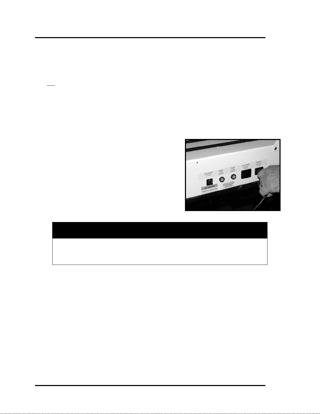
Use the power cord supplied with the machine and plug it into a properly grounded wall outlet located near the
machine and easily accessible. Failure to properly ground the machine can result in sever personal injury and/or
fire.
The power cord and wall plug is the primary means of disconnecting the machine for the power supply.
DO NOT use an adapter plug on the line cord or wall outlet.
DO NOT remove the ground pin from the line cord.
DO NOT route the power cord over sharp edges or trapped between furniture.
Avoid using wall outlets controlled by wall switches, or shared with other equipment.
Make sure there is no strain on the power cord caused by jamming between the equipment, walls or furniture.
DO NOT remove covers. Covers enclose hazardous parts that should be accessed by a qualified service
representative. Report any damage of covers to your service representative.
This machine requires periodic maintenance. Contact your authorized service representative for required
service schedules.
To prevent overheating, do not cover the vent openings.
Use this equipment only for its intended purpose.
DO NOT allow the conveyor or dryer to operate unattended.
Follow any specific occupational safety and health standards for your workplace or area.
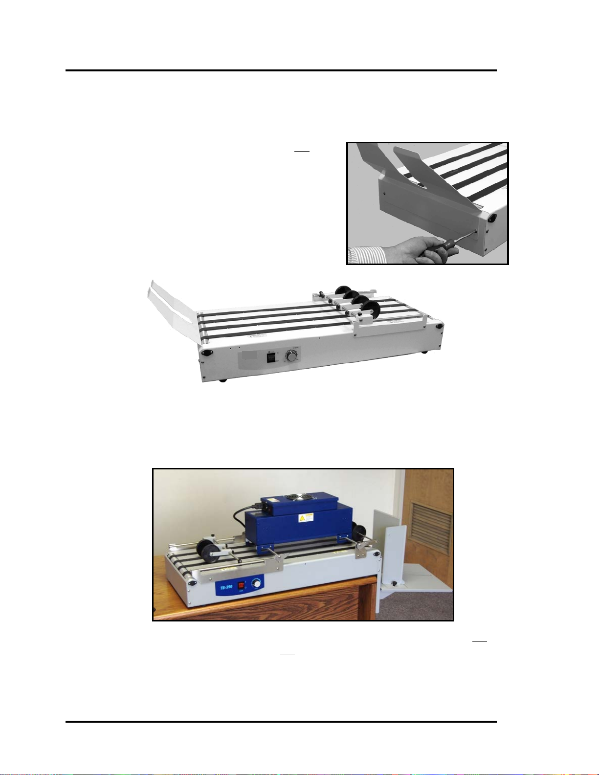
Dryer Safety Warnings/Precautions:
∗The dryer should not be turned on unless the conveyor belts are moving.
∗The dryer lamps, dryer surfaces and conveyor surfaces will get very hot and can cause injury. Keep all
body parts, clothing, hair, and flammable materials away from the dryer and hot surfaces.
∗If a flammable item comes in contact with the dryer or dryer lamps, there is a chance that it can catch fire.
If a material jam occurs; turn off the conveyor and dryer immediately. Keep a properly rated fire
extinguisher within reach when operating the dryer.
This manual is intended solely for the use and information of Neopost USA, Inc., its designated agents, customers,
and their employees. The information in this guide was obtained from several different sources that are deemed
reliable by all industry standards. To the best of our knowledge, that information is accurate in all respects.
However, neither Neopost USA, Inc. nor any of its agents or employees shall be responsible for any inaccuracies
contained herein.
All rights reserved. No part of this book may be reproduced or transmitted in any form or by any means, electronic or mechanical, including
photocopying, recording, or any information storage and retrieval system, without permission in writing from the publisher.

TB-390 Operations Rev. 7/30/2014
4
UNPACK THE CONVEYOR
Please save the packaging for possible future use.
If you plan to discard the packaging; do so in an environmentally appropriate manner.
Do not discard the packaging until the conveyor is fully assembled.
POWER CONNECTION
IMPORTANT! The TB-390 is manufactured for use on a specific AC voltage source. Before
connecting the power cord to the conveyor; verify that you are connecting the unit to a
compatible AC voltage source. See the conveyor’s serial tag for the voltage rating of your unit.
1. Check to be sure the Power Switch, at the front
of the conveyor, is off (zero position).
2. Connect the supplied power cord to the “Power
In” receptacle on the conveyor. Plug the other
end of the power cord into a properly grounded
wall outlet.
TEST FOR APPROPRIATE TRANSPORT DIRECTION
The TB-390 can be configured to run from “right to left” or from “left to right”.
1. Turn on the Power Switch.
2. Turn up the speed control dial, so the transport belts are moving.
3. Make note of the direction of transport. Left to Right or Right to Left.
4. If the transport direction is not appropriate, for your application, it will need to be
reversed. See the section titled “Reverse Operation” before proceeding.
CAUTION
THE CONVEYOR IS DESIGNED TO BE PLUGGED INTO A GROUNDED
OUTLET. FOR YOUR SAFETY, DO NOT REMOVE THE GROUND PIN FROM
THE LINE CORD.

TB-390 Operations Rev. 7/30/2014
5
DROP-TRAY INSTALLATION
If you plan to install the optional dryer, please read the section titled “Dryer Mounting Kit
Instructions” before proceeding.
To assemble and install the Drop-Tray on the Conveyor follow these steps:
1. Disconnect the power cord from the unit.
2. If installed; remove the two screws holding the optional
back-stop to the conveyor and remove the back-stop.
See the “Optional Accessories” section, for more info on
the optional back-stop.
3. At the exit end of the conveyor; remove the four screws
[A] that mount the cover plate to the conveyor. Do not
remove the cover plate.
Note: The TB-390 can be configured to run from “right to left”
or from “left to right”. The exit end of the conveyor is
determined by the direction of the conveyor.
4. While holding the cover plate in place; install the Drop-
Tray Support Bracket [B], to the exit end of the conveyor,
using the four screws removed in Step 2.
5. Install the Paper Guide Roller assembly, to the exit end of
the conveyor, using the four screws supplied [C]. The
Paper Guide Roller assembly should be mounted as shown
with the rollers resting on the exit roller of the conveyor.

TB-390 Operations Rev. 7/30/2014
6
6. Hook the Tray Base into the desired slots on
the Drop-Tray Support Bracket. The Tray
Base position may be adjusted left or right,
depending on media exit position, and up or
down to provide more or less stack height.
7. Remove the knobs and securing plates from
the guides. Attach the guides to the Tray Base
as shown. The largest guide is the Paper Stop
Guide. The Paper Stop Guide is installed on
the slot that runs most of the length of the
Tray Base. The Wide Side Guide is installed
on either of the two slots at the side of the Tray Base (slot position determined by
media length). The Narrow Side Guide can be installed on any of the threaded holes
in the Tray Base (hole position determined by media size).
POSITIONING THE CONVEYOR
1. The conveyor should be placed at the exit end of the
printer or tabber, as shown.
When using the drop-tray, the conveyor must be
positioned so the drop-tray hangs off the end of the
table.
The work surface or table must be capable of
properly supporting the weight of the conveyor and
the printer or tabber.
2. Center the conveyor at the exit end of the printer or
tabber.
T-350 Dual Tabber, and TB-390 Conveyor
Envelope Imager 2.5 and TB-390 Conveyor

TB-390 Operations Rev. 7/30/2014
7
Power
Switch
Speed
Control
OPERATING THE CONVEYOR
1. Connect power to the conveyor. See the
section titled “Power Connection”.
2. Turn on the conveyor and the printer or
tabber.
3. Feed a single piece of stock through the
printer or tabber and onto the conveyor.
Observe the way it is received by the
conveyor.
4. Loosen the locking knob [A] and adjust the
position of the stacking wheel assembly so that
the lead edge of the media just touches the
stacking wheels, as it exits the printer or tabber.
5. Adjust the speed control knob to set the desired
conveyor transport speed.
Clockwise = Faster (bigger gap between pieces or
less overlap).
Counter-clockwise = Slower (smaller gap between
pieces or more overlap).
Note: When the optional back-stop is used; the speed of the conveyor must be set so that
adjacent pieces are overlapping each other.
When the standard drop-tray is used the media does not need to be overlapped.
REVERSE OPERATION
The TB-390 can be configured to run from “right to left”
or from “left to right”.
If the conveyor is not running in the desired direction, it
can be reconfigured as follows:
1. Disconnect the power cord from the conveyor.
2. Slide the position of the “transport direction
switch”, located under the conveyor, to the
opposite position.
3. Reconnect the power cord to the conveyor.
4. If necessary; move the guide roller assembly and the stacking tray (back-stop or drop-
tray) to the opposite end of the conveyor.

TB-390 Operations Rev. 7/30/2014
8
TROUBLESHOOTING
If the conveyor should fail to run, check for jammed paper between the belts and roller.
Also, check the fuses and motor circuit breaker. Replace fuses or reset breaker as necessary.
The fuse holders and circuit breaker are located on the rear of the conveyor.
WARNING
DISCONNECT THE POWER CORD WHEN CHECKING OR
REPLACING FUSE!
EVEN IF THE BREAKER OR ONE OF THE FUSES BLOWS; SOME
ITEMS ON/IN THE CONVEYOR WILL STILL HAVE POWER!
ALWAYS REPLACE THE FUSE WITH THE SAME TYPE. FAILURE TO
DO SO MAY DAMAGE THE ELECTRONIC CIRCUIT BOARD.
Fuse Ratings: 0.5 Amp x2, 250V, slow blow.
Problem
Possible Cause/Solution
No Operation
No AC Power
Turn on conveyor’s power switch.
Verify that power cord is properly connected from wall
outlet to conveyor.
Check fuses and breaker on conveyor.
Check voltage from wall outlet.
Conveyor Runs, but
Dryer Won’t Turn On
Dryer power is only enabled when conveyor’s power
switch is on.
Verify that dryer power cord is properly connected from
dryer to “dryer out” outlet on conveyor.
Check fuses on dryer.
Dryer Turns On, but
Conveyor Won’t Run.
Turn up conveyor speed control.
Check fuses and breaker on conveyor.
Note: Even if the conveyor’s breaker is tripped or the fuses
are blown, power is still applied to the “dryer out” outlet
when the conveyor’s power switch is on.

TB-390 Operations Rev. 7/30/2014
9
OPTIONAL ACCESSORIES
Back-stop (Part #: 57E-601-16)
Important: The optional back-stop can not be
used when the optional dryer is installed.
1. If the drop catch tray is installed it must
be removed before you can attach the
back-stop.
2. Attach the back-stop to the conveyor,
using the two screws provided.
Dryer (Part #: DRYER IR7C or DRYER IR7C 220V)&
Dryer Mounting Kit (Part #: DKE-700)
An optional 700 watt dryer is available for use on the TB-390.
To help prevent damage to the conveyor and conveyor belts; the dryer should not be
powered on if the conveyor belts are not moving. See the “Safety Precautions” section.
Please see the next section for “Dryer Mounting Kit Instructions”.

TB-390 Operations Rev. 7/30/2014
10
Dryer Mounting Kit Instructions
Note: The images shown in this procedure depict a conveyor that is being setup for right to left
transport. If you plan to use your conveyor for left to right transport; the items shown in this
procedure must be attached at the opposite sides of the conveyor.
In addition; the dryer images, shown in this procedure, are of an older dryer model.
1. Disconnect the power cord from the conveyor.
2. To install the Dryer Mounting Kit (DKE-700) you must first remove the following parts
from the TB-390.
A. Stacking Tray [A] (2 screws)
Important: The optional back-stop
can not be used when the optional
dryer is installed.
B. Guide Assembly [B] (4 screws)
Remove the operator’s side bracket
first, then the rear support bracket.
3. Install the new Rear Roller Support [C], to the
entrance end of the conveyor, using two
screws as shown.
Note: As viewed from back side of conveyor.
Conveyor being used for right to left transport.
4. Hook the Guide Roller Support over the shaft
on the rear roller support [1], and then install
the Front Roller Support using two screws [2]
as shown.
Note: As viewed from operator (front) side of
conveyor. Conveyor being used for right to left
transport.
5. Next install the Front Exit Roller Assembly, to the
exit end of the conveyor, by attaching the mounting
brackets to the frame of the conveyor as shown using
two screws each side [3].
Note: As viewed from operator (front) side of conveyor.
Conveyor being used for right to left transport.

TB-390 Operations Rev. 7/30/2014
11
6. Remove the two Levers [4] and Bearing
Washers [5] from the two Dryer Support
Shafts [6]. Install the two shaft assemblies
into the holes provided in the Dryer as
shown. Reinstall the two Levers [4] and
Bearding Washers [5] to the shafts.
NOTE: When installing the two Levers [4]
make sure that the cams on the opposite side
of the shaft are in the same position as the
cams on the levers.
The dryer images shown are of an older dryer model.
7. The Dryer Assembly can now be placed in
the support brackets. Make sure that the
Bearing Washers are between the support
brackets and the cams as shown.
Note: Image depicts conveyor being used for
right to left transport.
NOTE: The Bearing Washers should go between the
support brackets and the cams.

TB-390 Operations Rev. 7/30/2014
12
8. Plug the cord supplied with the Dryer into the
receptacle on the Dryer and then into the
Receptacle labeled Dryer on the Conveyor.
Then plug the Conveyor into the wall outlet.
CAUTION: Conveyors and Dryers are
available in 115V and 230V versions. Verify
the conveyor and dryer voltage ratings,
before connecting them to an appropriate
power source.
Note: The dryer images shown in the rest of this
procedure are of an older dryer model.
The image to the right; can be used to identify the
locations for the power receptacle and power
switch on the newer dryer models.
9. Install the Drop-Tray. See the section titled “Drop-Tray Installation”.
Important: The optional back-stop can not be used when the optional dryer is installed.
10. Connect the power cord to the conveyor. See the section titled “Connecting Power”.
11. To operate the Dryer first set the two levers [4] so
that the media can pass under the dryer without
interference.
Then turn on the dryer’s power switch ON and
finally turn on the conveyor’s power switch.
NOTE: The dryer will not operate if the conveyor
is not turned ON.
12. To accommodate different sized media and different
drying areas; the Dryer and the Guide Rollers may be adjusted from side to side, by
sliding them on the shaft assemblies.
CAUTION
DO NOT OPERATE THE DRYER IF THE BELTS ON THE CONVEYOR ARE NOT MOVING.
DO NOT BLOCK THE EXIT OF THE CONVEYOR WHEN USING THE DRYER.
IF A MATERIAL JAM OCCURS; TURN OFF THE CONVEYOR AND DRYER IMMEDIATELY!
PLEASE READ THE “SAFETY PRECAUTIONS” SECTION IN THIS MANUAL!

TB-390 Operations Rev. 7/30/2014
13
Notes

Copyright © 2014 NEOPOST USA
Table of contents
Popular Accessories manuals by other brands

CASUALPLAY
CASUALPLAY LOOP instructions

Patton electronics
Patton electronics 592 user manual

Malmbergs
Malmbergs 99 751 42 instruction manual

MDT Technologies
MDT Technologies SCN-LSEN1.01 Technical manual

Reiner
Reiner jetStamp 790 operating instructions

Servodan
Servodan 41-201 Fitting and operating instructions