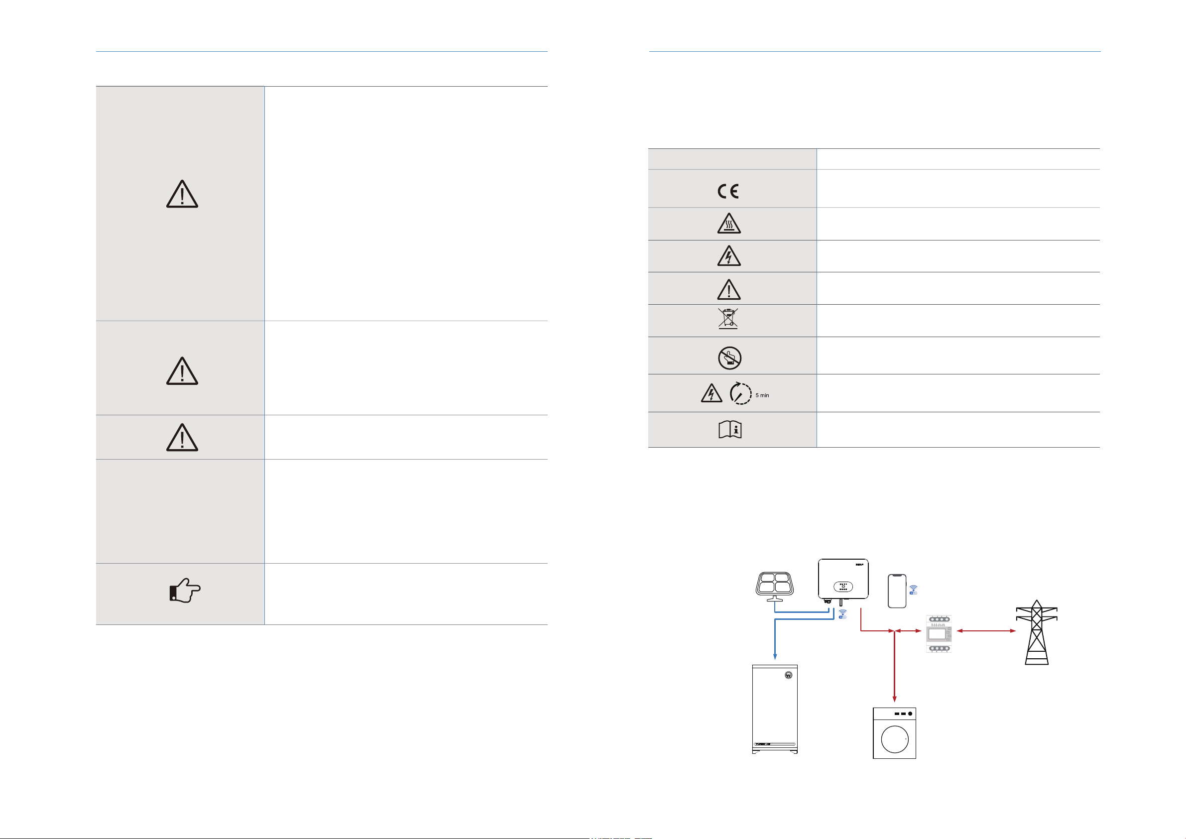
Renac N3-HV Series User manual

N3-HV-5.0
N3-HV-6.0
N3-HV-8.0
N3-HV-10.0
User Manual
Series
N3-HV

1. About This Manual 3
1.1 Applicability 3
1.2 Target group 3
1.3 Symbols used 3
2. Safety 3
2.1 General Safety 3
2.2 Important safety instructions 3
2.3 Explanation of symbols 5
3. Introduction 5
3.1 Basic features 5
3.2 Work modes 6
3.3 Terminals 8
3.4 Dimension 9
4. Technical data 9
5. Installation 11
5.1 Unpacking 11
5.2 Check for transport damage 13
5.3 Installation precaution 13
5.4 Available space 13
5.5 Preparation 13
5.6 Installation steps 15
5.7 Electrical Wiring Connection 16
5.7.1 PV Wiring Connection 17
5.7.2 Battery Connection 18
5.7.3 AC Output Connection 20
5.7.4 Earth Connection 21
5.7.5 Communication connection 22
5.8 Inverter manipulation 24
6. Operation method 25
6.1 Control panel 25
6.2 LCD function 26
6.3 LCD operation 27
7. Troubleshooting 33
8. Decommissioning 37
8.1 Dementling the inverter 37
8.2 Packaging 37
8.3 Storage 37
8.4 Disposal 37
Content

2 3
This manual contains important safety instructions that must be followed during installation and maintenance of the equipment.
IMPORTANT TO READ CAREFULLY AND KEEP FOR POSSIBLE CONSULTATIONS
Notice
Save the manual!
RENAC Power reserves the right of final interpretation. This manual may be updated according to user’s or customer’s feedback.
The information in this manual is subject to change without notice. Please check our website at http://www.renacpower.com for
latest version.
Copyright Declaration
All rights to the content of this manual are owned by RENAC Power Technology Co., Ltd. (hereinafter called as ‘RENAC Power’). Any
corporation or individual should not plagiarize, partially copy or fully copy it, and no reproduction or distribution of it in any form or by
any means without prior written permission from RENAC Power.
1. About This Manual
1.1 Applicability
2. Safety
2.1 General Safety
Please read the product manual carefully before installation,operation or maintenance.This manual contains important safety instruc-
tions and installation instructions that must be followed during installation and maintenance of the equipment.
2.2Important safety instructions
1.2 Target group
This manual is intended for qualified electrical technical personnel who are responsible for hybrid inverte installation and
commissioning in the energy storage system.
1.3 Symbols used
The following types of safety instructions and general information appear in this document as described below:
DANGER!
‘Danger’ indicates a hazard with a high level of risk that, if not avoided,
will result in death or serious injury.
WARNING!
‘Warning’ indicates a hazard with a medium level of risk that, if not avoid-
ed, will result in death or serious injury.
CAUTION!
‘Caution’ indicates a hazard with a low level of risk that, if not avoided,
could result in minor or moderate injury.
NOTICE!
‘Notice’ indicates a situation that, if not avoided, could result in equip-
ment or property damage.
NOTE!
‘Note’ provides tips that are valuable for the optimal operation of your
product.
N3-HV-5.0 N3-HV-6.0 N3-HV-8.0 N3-HV-10.0
The hybrid inverter has been designed and tested strictly according to international safety regulations. Read all safety instructions
carefully prior to any work and observe them at all times when working on or with the hybrid inverter. Incorrect operation or work
may cause:
◆injury or death to the operator or a third party;
◆damage to the inverter or other properties.
NOTICE
N3-HV Series User Manual N3-HV Series User Manual

4 5
3.1 Basic features
The N3-HV Series hybrid inverters apply to PV energy storage system with PV modules, battery, loads and grid.
The energy produced by PV system shall be used to optimize self-consumption, excess power charge battery and the rest power could
be fed into the grid. Battery shall be discharged to support loads when PV power is insucient to meet self-consumption. If both PV
power and battery power is insucient, the system will take power from grid to support loads.
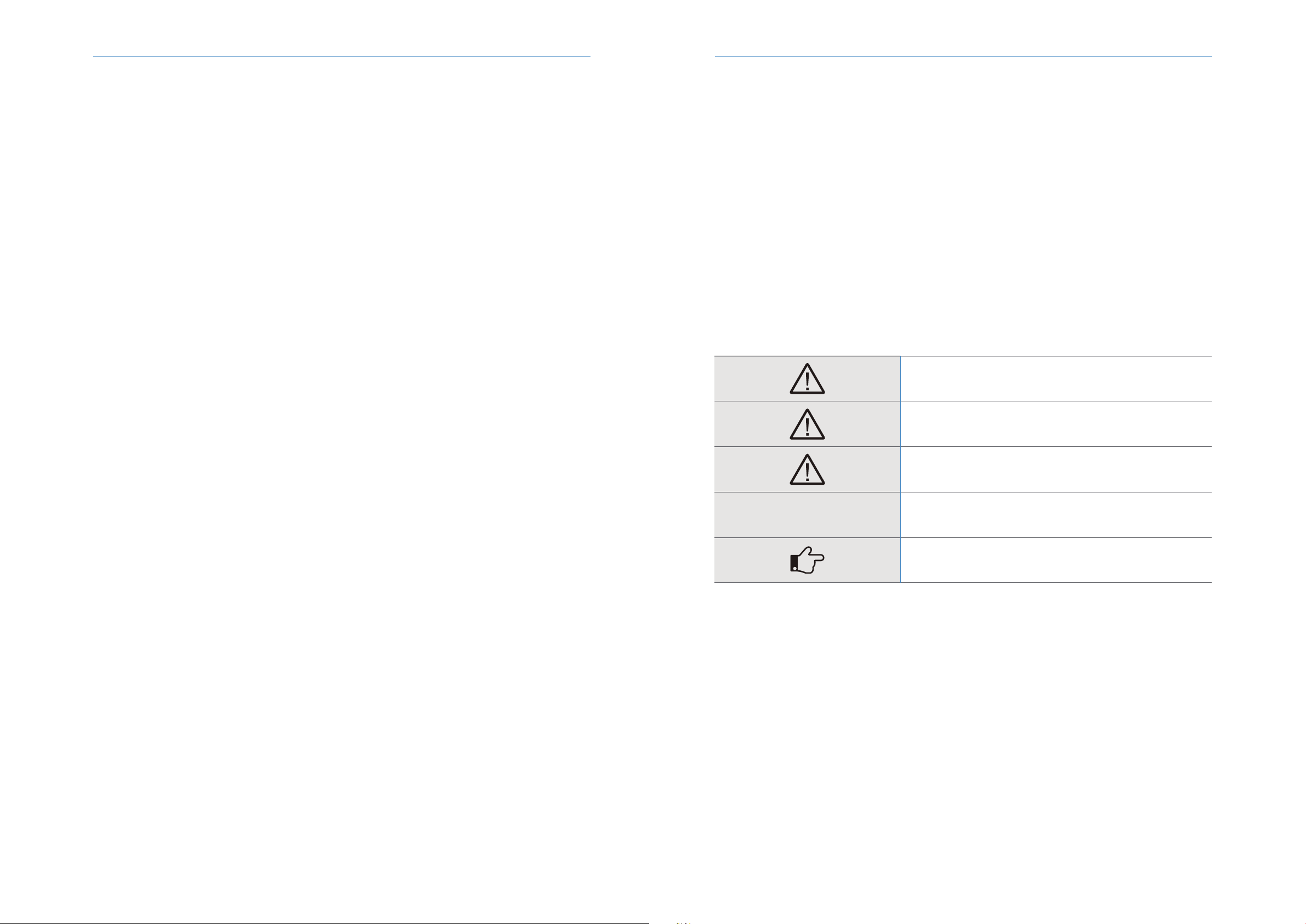
CE mark. The inverter complies with the requirements of the applicable CE
guidelines.
Danger of high voltages.
Danger to life due to high voltages in the inverter!
Danger.
Risk of electric shock!
The inverter cannot be disposed of together with the household waste.
Disposal information can be found in the enclosed documentation.
Don’t work on this inverter until it is isolated from battery, mains and on-site
PV generation suppliers.
Danger to life due to high voltage.
There is residual voltage in the inverter which needs 5 min to discharge.
Wait 5 min before you open the upper lid or the DC lid.
Please read this manual before installation
Beware of hot surface.
The inverter can become hot during operation. Avoid contact during opera-
tion.
Symbol Explanation
PV Panels
Battery Normal Load
Grid
Meter
Hybrid Inverter
Monitor
DANGER!
◆PV strings will produce electrical power when exposed to sunlight and
can cause a lethal voltage and an electric shock.
◆Only qualified personnel can perform the wiring of the PV panels.
◆Do not open the enclosure when the inverter is running. Unauthorized
opening will void warranty and warranty claims and in most cases termi-
nate the operating license.
◆When the enclosure lid is removed, live components can be touched
which can result in death or serious injury due to electric shock.
◆Operating a damaged inverter can lead to hazardous situations that can
result in death or serious injuries due to electric shock.
◆Batteries deliver electric power, resulting in burns or a fire hazard when
they are short circuited, or wrongly installed.
◆Lethal voltages are present at the battery terminals and cables
connecting to the inverter. Severe injuries or death may occur if the
cables and terminals in the inverter are touched.
◆PV negative (PV-) and battery negative (BAT-) on inverter side is not
grounded as default design. Connecting PV- or BAT- to EARTH are strictly
forbidden.
WARNING!
◆Do not disconnect PV connectors, AC connector or battery connectors
while the inverter is running. De-energize from all multiple power sourc-
es. Wait 5 minutes for the internal capacitors to discharge. Verify that
there is no voltage or current before disconnecting any connectors.
Use personal protective equipment, including rubber gloves and prote-
tive boots during the installation or maintenance.
CAUTION!
Do not touch any hot parts (such as the heat sink) during operation, The
temperature of inverter surface might exceed 60℃ during working
CAUTION!
◆Electrical installation and maintenance must be carried out by compe-
tent electricians according to local regulations.
◆Do not open inverter cover or change any components without RENAC
Power’s authorization, otherwise the warranty commitment for the
inverter will be invalid.
◆Usage and operation of the inverter must follow instructions in this user
manual, otherwise the protection design might be useless and warranty
for the inverter will be invalid.
NOTE!
◆Electrical installation and maintenance must be carried out by compe-
tent electricians according to local regulations.
The inverter built-in RCMU will exclude possibility of DC residual current
to 6mA, thus in the system an external RCD (type A) can be used(≥30mA).
Anti-Islanding Effect
Islanding effect is a special phenomenon that grid-connected PV system still supply power to the nearby grid when the
voltage loss is happened in the power system. It is dangerous for maintenance personnel and the public.
N3-HV series inverter provide Active Frequency Drift(AFD) to prevent islanding effect.
NOTICE
N3-HV Series User Manual N3-HV Series User Manual
2.3 Explanation of symbols
This section gives an explanation of all the symbols shown on the type label.
Symbols on the Type Label

6 7
3.2 Work modes
The N3-HV Series hybrid inverter has the following work modes based on your configuration and layout conditions.
Work mode: Self-use
Priority: load>battery>grid
Self-consumption of PV renewable energy is the highest priority. The PV excess is used to charge the batteries, then fed back
into the grid.
Priority:load>grid>battery
This mode applies the area that has high feed-in tariff and export control. The PV generated power will be used to supply the loads
firstly, then feed into the grid. The excess power will charge the battery.
Work mode: Feed in Pirority
1) Generated solar energy
2) Load consumption
3) Storage in battery
4) Feed the excess solar energy into the grid
1) Generated solar energy
2) Load consumption
3) Feed into grid
4) Charge the battery
34
1
2
This mode applies the area that has electricity price between peak and valley. User can use off-peak electricity to charge the battery.
The charging and discharging time can be set flexibly, and it also allows choosing whether charge from the grid or not.
Work mode: Force time use
Priority: battery>load>grid (when charging)
Priority: load>battery>grid (when discharging)
1) Generated solar energy
2) Storage in battery
3) Load consumption
4) Grid supply power when the battery capacity is not enough
1) Generated solar energy
2) Load consumption
3) Self-use from battery
4) Grid supply power when the battery capacity is not enough
24
1
3
34
1
N3-HV Series User Manual N3-HV Series User Manual
4
3
2
1

89
3.3 Product overview
Work mode: Back up mode
Priority: battery>load>grid
This mode applies the area that has frequent power outages. And this mode ensures the battery will has enough energy to supply
during a grid outage. The back up load could be supported by PV and battery in the event of a blackout.
1) Generated solar energy
2) Storage in Battery
3) Load consumption
4) Grid supply power
24
1
3
WARNING!
Make sure the load powering rating in within the EPS’s output rating. Or the
inverter will shut down with an ‘over load’ warning.
When an ‘over load’ is appeared, adjust the load power make sure it is with
the range of the EPS output, and turn the inverter on.
For the nonlinear load, please pay attention to the inrush power make sure it
is within the range of the EPS output.
4 Technical data
Object
Communication port
DC switch
WiFi or GPRS port
PV connectors
A
B
C
D
Battery connectorsE
F
G
H
I
EPS port
Grid port
SD port
USB port
Description Object Description
3.4 Dimension
9000 15000
7500 12000
1000
160~960
600
160
2
1
18 / 18
23/23
0
Integrated
Model
PV Input Data
N3-HV-8.0N3-HV-6.0 N3-HV-10.0N3-HV-5.0
Max. Recommended PV Power (W)
Max.DC Input Voltage (V)
MPPT Voltage Range (V)
Rated DC input voltage (V)
Start-up Voltage
No. of MPP Trackers
No. of Input Strings per Tracker
Max. DC Input Current (A)
Max. Short Circuit Current(A)
Backfeed Current to Array(A)
DC Switch
N3-HV Series User Manual N3-HV Series User Manual
B D ECA F G H I
520.00 187.00
412.00
6000
9.1
3 /N / PE, 220 / 380, 230 / 400
50 / 60; ± 5
0.8 leading ~ 0.8 lagging
< 3
10000
15.2
5000
7.6
8000
12.2
AC Output Data
Rated AC Power (W)
Maximum contiouous AC Current (A)
Rated AC Voltage / Range (V)
Grid Frequency / Range (Hz)
Adjustable Power Factor [cosφ]
Output THDi (@Rated Output) (%)

10 11
12000
18.2
3 /N / PE, 220 / 380, 230 / 400
50 / 60
32
40
73
Lithium
160 ~ 700
30
CAN
20000
30.4
10000
15.2
16000
24.3
6000 10000
5000 8000
98.00%
97.70%
97.60%
98.00%
97.70%
97.60%
98.00%
97.70%
97.60%
98.00%
97.70%
97.60%
9.1 15.2
7.6 12.2
6000 10000
5000 8000
9000, 60 15000, 60
7500, 60 12000, 60
3 / N / PE, 220 / 380, 230 / 400
50 / 60
< 3%
< 10
Intergrated
Intergrated
Intergrated
Intergrated
Intergrated
Intergrated
AC Input Data Intergrated
Intergrated
Type II
Type II
520 * 412 * 186
27
LED+OLED
RS485 and USB or Wifi or 4G (Optional)
-25 ~ +60
0% ~ 100%
≤ 4000
<15
Transformerless
II
I
DC II / AC III
Outdoor conditioned
Natural
IP65
< 35
5
General Data
Certifications & Standards
AC Short-circuit Protection
AC Overvoltage Protection
DC Surge Protection
AC Surge Protection
Size (Width * Height * Depth mm)
Weight (kg)
User Interface
Communication
Operating Temperature Range (℃)
Relative Humidity (%)
Operating Altitude (m)
Standby Self Consumption (W)
Topology
Pollution degree
Protective class
OVC categories
Environmental categories
Cooling
Protection Grades
Noise (dB)
Warranty (years)
Grid Regulation
Safety Regulation
EMC
5 Installation
5.1 Unpacking
Check the delivery for completeness. Contact your dealer at once if anything is missing.
N3-HV Series User Manual N3-HV Series User Manual
AS 4777,EN 50549,IEC 61727,CEI 0-21, EC 62116,lEC 60068,IEC 61683
IEC 62109-1,IEC 62109-2,IEC 62040
EN 61000-6-2,EN 61000-6-3,EN 61000-4-16,EN 61000-4-18,EN 61000-4-29
Rated AC Power (W)
Maximum contiouous AC Current(A)
Rated AC Voltage / Range (V)
Grid Frequency / Range (Hz)
AC Inrush Current (A)
Maximum Output Overcurrent Protection
AC Maximum output fault current (A)
Battery Type
Battery Voltage Range (V)
Max. Charging / Discharging Current (A)
Communication Interface
EPS Rated Power (W)
EPS Rated Voltage (V)
EPS Rated Frequency (Hz)
EPS Rated current (A)
Output THDi (@Rated Output) (%)
Automatic Switch Time (ms)
Peak Apparent Power (rated).Duration (s)
Max. Eciency (%)
Euro Eciency (%)
Max. Battery Discharge Eciency (%)
DC Insulation Monitoring
Input Reverse Polarity Protection
Anti-island Protection
Residual Current Monitoring
Over-heat Protection
AC Overcurrent Protection
Eciency
Output DC( Battery)
EPS Output (With Battery)
Protection

1312
Object Quantity Description
A
B
C
D
E
F
G
H
I
J
K
L
M
N
O
P
1
1
2
4
4
1
1
1
1
5
1
1
4
1
1
1
N3-HV inverter
Bracket
Battery Connectors (1* positive, 1*negative)
PV Connectors (2* positive, 2*negative)
PV Pin contact (2* positive, 2* negative)
AC Terminal
EPS Terminal
8P Pluggable Terminal Block
WiFi or GPRS Module(Optional)
Ethernet RJ45 Connector
M5 Screw
Earth Terminal
Expansion tubes& Expansion screws
Meter
User Manual & Quick installation guide
Quality Certificate
Open the package and pick the product, check that if there is any distortion or impaired during the transportation. Meanwhile,
check that if the relating accessories and the materials are here, you can see the accessories list in the table.
The instruction manual is an integral part of the unit and should therefore be read and kept carefully.
It is recommended that the packaging should not be removed until the unit is located in the installation site.
5.2 Check for transport damage
Check if the N3-HV series inverter has some visible external damage, such as cracks in the housing or display please contact
with your dealer if you find any damage.
5.3 Installation precaution
The N3-HV series inverter is designed for outdoor installation (IP65)
Make sure the installation site does not fall into one of the following conditions:·Do not install the inverter in direct sunlight.
·Do not install the inverter on flammable construction material.
·Do not install the inverter in areas where highly flammable materials are stored.
·Do not install the inverter in potentially explosive areas.
·Do not install the inverter during periods of precipitation or high humidity (>95%); Moisture trapped within the location may
cause corrosion and damage to the electric components.
·Provide adequate ventilation when using batteries, and also read the warning label on the bottom of the inverter.
·Install the inverter in a location that maintains an ambient air temperature that is less than 40°C;That is to maintain a safe
internal component temperature; the inverter would reduce power if the ambient air temperature exceeds 40°C. • The inverter
should be installed in a location that is not accessible for children.
·The inverter emits a slight vibrating noise when operating, which is normal and no effect on performance.
·The slope of the wall should be within ±5°.
·The inverter is heavy, ensure the mounting place is strong enough to hold the weight of the inverter.
·If you install the inverter in a cabinet, closet or other small enclosed area, sucient air circulation must be provided in order
to dissipate the heat generated by the unit.
Figure 5-1 inverter space size
5.4 Available space
500mm
500mm
300mm
A B C D
E F G H
I J K L
M N OP
N3-HV Series User Manual N3-HV Series User Manual
300mm300mm

14 15
Lifting and Handling
The unit is heavy. Do not lift it alone.
·During lifting procedures ensure that the unit is firmly secured to avoid the risk of accidental tipping or dropping.
·Parts serving for support or immobilization of unit shall be designed and manufactured so as to minimize the risk of physical
injuries and of accidental loosening of fixing.
·Ensure that the method of lifting will not allow the unit to slip from chains and slings or turn-over or slide from lifting devices.
5.5 Preparation
No. Tool Model Function
1
2
3
4
5
6
7
8
9
Level
BOSCH HD18-2 Two-
Speed Hammer Dril
Make sure the bracket is
properly installed
Drill holes on the wall
Hanging the bracket
Hanging the bracket
Strippling plier for PV cable
Crimping plier for PV cable
Crimping tool for RJ45 terminal
Crimping Tool For Insulated
Electrical Connectors
Wiring
KIMO 20V 1/2 Cordless
Brushless Impact
Wrench Set
PV-AZM-410
PV-CZM-22100
Screwdriver
RJ45 Crimping Tool
Crimping plier
Hammer
5.6 Installation steps
Step 1: Screw the wall bracket on the wall
·Use the wall bracket as a template to mark the position of the 4 holes.
Step2: Hang the N3 HV inverter on the wall bracket.
·Transportation of the inverter needs at least 2 people, each one needs to use the handles at the sides of the inverter.
·Hang the inverter over the bracket, move the inverter close to it, slightly laydown the inverter make sure the 4 mounting bars
on the back of the inverter is fixed well with 4 grooves on the bracket.
·Drill holes with ф10 driller carefully, make sure the holes are deep enough (at least 45mm) for install and tight the expansion
tubes.
·Install the expansion tubes in the holes, and tight them. Install the wall bracket using the expansion screws in the screw
package.
·Transportation must be carried by specialized person (truck operators. Hook-up personal), equipped with the necessary
protection equipment (overalls, safe shoes, protective gloves, helmets, goggles)
·Do not walk or stand beneath or in the proximity of the load.
·Avoid sudden movements and jolts when unloading and positioning the unit. Internal handling procedures must be conducted
with care. Do not exert leverage on the components of the machine.
·If the unit is not balanced apply ballast. Any protruding parts should not be supported by hand.
·The inverter should be installed so that the operating panel shall be easily accessible- easy access to the electrical power
connection point.
·Accessible for maintenance and repair work.
·Parts serving for support or immobilization of unit shall be designed and manufactured so as to minimize the risk of physical
injuries and accidental loosening of fixings.
·Loading capacity and hardness of the supporting surface, load rating of mounting bracket should be at least four times the
weight of the devices according to IEC62109-1. And supporting characteristics will be impaired by wear, corrosion, material
fatigue or ageing, This should be calculated by inspection of the design data of supporting material and consulting construction
engineer.
N3-HV Series User Manual N3-HV Series User Manual

16 17
5.7 Electrical Wiring Connection
The overview of the connection terminals of inverter please refer to Figure 3-2, and the wiring connections please refer to
Figure 3-1 the PV energy storage system wiring diagram in chapter 3.1.
System Connection Diagrams
Note: This diagram is an example for Australian,South Africa and New Zealand grid system where neutral line can't be switched.
5.7.1 PV Wiring Connection
Before connecting PV strings to N3-HV Series hybrid inverter, please make sure requirements are followed as below :
·The total short- circuit current of PV string must not exceed inverter’s max DC current .
·Make sure open circuit voltage of PV string is less than 1000V.
·PV strings could not connect to earth/grounding conductor.
·Use the right PV plugs in the accessory box, BAT plugs are similar with PV plugs, please confirm before use it.
1.Turn off the DC switch.
2.Prepare 2.5-4mm2 PV cable and PV plugs as below.
3.Strip 7mm of the conductor with stripping plier. Use a suitable stripping tool for this (e.g. "PV-AZM-410 ")
4.Insert striped cable into pin contact and ensure all conductor strands are captured in the pin contact.
5.Crimp pin contact by using a crimping pliers(PV-CZM-22100). Put the pin contact with striped cable into the corresponding
crimping pliers and crimp the contact.
6.Insert pin contact through the cable nut to assemble into back of the male or female plug. When you feel or heard a ‘click’ the
pin contact assembly is seated correctly.
·PV string connection
·Battery connection
·Battery power connection
·Battery communication connection
·AC output connection
·EPS connection
·Earth connection
·Communication connection
The main steps to connect the N3 HV series system
Connection Steps:
Note: This diagram is an example for grid system without special requirement on electrical wiring connection.
N3-HV Series User Manual N3-HV Series User Manual
PV panels
EPS Grid
N3 HV Series inverter
PV BAT
Normal loads
Meter
R
S
T
N
R
S
T
N
PE
RCDRCD
Critical loads
PV panels
EPS Grid
N3 HV Series inverter
PV BAT
Normal loads
Critical loads
Meter
RCD RCD
PE
PE PEN NT TS SR R
PE PEN NT TS SR R

18 19
5.7.2 Battery Connection
When you want to build a self-use storage system, the high voltage battery is a necessary part. The N3 HV series inverter
provides the necessary part of the interfaces to connect the battery.
WARNING!
Make sure you select the correct specification cables fo installation.
Otherwise the power will make the cable hot or burnt; it could result in death or serious injury.
7.Tight the DC connector.
a.Slide the cable nut towards the back shell.
b.Rotate the cable nut to secure the cable.
8.After securing the cable tightly, align the 2 half connectors and mate them. together by hand until a ‘click’ is felt or heard.
9.Separate the DC connector
a.Use the specified wrench tool.
b.When separate the DC+ connector, push the tool down from upside.
c.When separate the DC- connector, push tool down from the bottom side.
d.Separate the connectors by hands.
1.Battery Power Cable Connection
1) Prepare the tin-plated cables with a conductor cross section of 4 to 6 mm² (AWG 10).
2) Strip 15mm off the conductor. Use a suitable stripping tool for this (e.g. "Knipex Solar 121211").
3) Open the spring using a screwdriver□.
4) Carefully insert the stripped wire with twisted litz wires all the way in (□, A). The litz wire ends have to be visible in the spring.
5) Close the spring. Make sure that the spring is snapped in (□, B).
1
2
2
2.Battery Communication Connection
The communication interface between battery and inverter is CAN with a RJ45 connector. The Pins definition is as below.
6.Push the insert into the sleeve (□, C).
7.Tighten the cable gland to 2 Nm (□, D).Use a suitable and calibrated torque wrench,size 15. Use an open-jaw wrench, size 16,
to hold the connector in place.
8.Fit the two connectors together until the connection audibly locks into place.
9. Check to make sure the connection is securely locked
10.Separating connectors
1). Insert the screwdriver into one of the four openings(□, A).
2). Leave the screwdriver in the opening. Pull the two connectors apart(□, B).
Pin 1
NC NC NC NC 485A 485BCANH CANL
23 4 5 6 7 8
Function
3
3
4
4
N3-HV Series User Manual N3-HV Series User Manual

20 21
5.7.4 Earth Connection
Connection step:
You can additionally earth the inverter enclosure of a second earthling or equipotential bonding is required locally. This
prevents touch current if the original protective conductor fails.
Cable size: 12AWG
·Strip the earthling cable insulation.
·Insert the stripped cable into the ring terminal.
·Clamp the end of the ring terminal.
·Unscrew the screw of the earthling connector.
·Suit the ring terminal on the earthling connector .Suit the gasket on the earthling
connector.
·Screw the screw of the earthling connector.
2.Remove the cable jacket by 40 mm, and strip the wire insulation by 8 mm–15 mm.
3.Fully insert the conductors to the corresponding terminal and tighten the screws with the torque 0.8 Nm. Pull cables outward
to check whether they are firmly installed.
4.Assemble the housing, the terminal block and cable gland (torque 4 Nm–5 Nm). Make sure that the rib of the terminal block
and the groove on the housing engage perfectly until a ‘Click’ is heard or felt.
5.7.3 AC Output Connection
N3 HV series inverters have already integrated RCMU (residual current monitoring unit) inside, however if an external RCD is
required, a type A RCD with rated residual current of 30mA or higher is recommended.
There are two AC terminals and the assembly steps for both are the same, just need to check one for ‘Grid’ another for ‘EPS’.
The AC cable and micro-breaker specification for AC side of N3 HV series inverter as below.
Connection Step:
1. Lead the AC cable through the cable gland and the housing.
WARNING!
Make sure you select the correct specification cables for installation.
Otherwise the power will make the cable hot or burnt; it could result in death or serious injury.
Don’t connect the phase to ‘PE’ terminal, otherwise the hybrid inverter will not function properly.
Overview for all battery connections
BMS
BAT+
BAT-
Model N3-HV-5.0
4mm2
10A 16A 16A 20A
4mm24mm24-6mm2
N3-HV-6.0 N3-HV-8.0 N3-HV-10.0
Cable(Cu)
Grid-Breaker
N3-HV Series User Manual N3-HV Series User Manual
40 mm
8 mm-15 mm
+ +
- -
20A 32A 32A 40A
Normal Load-Breaker
PE
L3
L2
L1
N

22 23
5.7.5 Communication connection
Communication interface
This product has a series communication interfaces besides WIFI or GPRS(optional), Dry contact and extend port and for
human and machine communication, etc., can be delivered to PC or other monitoring equipment via these interfaces.
1. WIFI or GPRS
The details please refer to the WIFI or GPRS module user manual.
3. METER port
Meter port PINS definition:
2. ADD Interface
ADD interface PINS definition:
Meter communication: METER_485A & METER_485Bpin1 & pin2
Relay contact output for generator: GENA & GENBpin3 & pin4
Shut down the hybrid inverter: +5V & SHUTDOWNpin5 & pin6
EPX box Relay & GND-pin7 and pin8
The function of meter port same as pin1 & pin2 of ADD interface.
Pin 1
METER-485A METER-485B GENA GENB +5V SHUTOWN Relay GND
23 4 5 6 7 8
Function
Pin 1
METER-485A METER-485B NC NC NC NC NC NC
23 4 5 6 7 8
Function
PV Panels
Battery Normal Load
Grid
Hybrid Inverter
RS485A
RS485B
N3-HV Series User Manual N3-HV Series User Manual
METER ADD Interface
BMS-CAN / 485
Parallel port
RS485
DRM
R
S
T
N
Meter1
Note:
The default address in the inverter software to recognize the meter is 1,so please confirm if the meter address is 1.Otherwise the
meter cant transfer the grid data to the inverter.
3.1 Meter wiring diagram for Typical Energy Storage System
2. RS485 Interface
RS485 interface PINS definition:
Pin 1
+5V GND 485A 485B
23 4
Function

6 Operation method
6.1 Control panel
3.2 Meter wiring diagram for AC Retrofit System
A B C D
E F G H
J
1) Grid-tied solar system has already existed.
2) More capacity of power is needed.
3) Battery is needed for emergency.
4) Extra space for PV panel.
Just add a meter between the grid-connected inverters and N3 HV hybrid inverter.
Note:
The default address in the inverter software to recognize the meter1, meter2 and meter3 is 001,002 and 003.(Refer to page 27)
So please set the meter1 address to 1, set meter2 address to 2, set meter3 address to 3.
Object Name
Indicator
LED
Function
Button
LCD Screen
Green: Normal working Status.
Red: Fault.
Blue: Battery communication status.
Yellow: RS485 communication status.
ESC button: Leave from current interface or function.
Up button: Move cursor to upside or increase value.
Down button: Move cursor to downside or decrease value.
OK button: Confirm the selection.
Display the information of the inverter.
Description
A
B
C
D
E
F
G
H
J
24 25
N3-HV Series User Manual
4. DRED
This application meets the requirements of local Australian grid code (AS/NZS 4777.2) which, among specific requirements for
connection, calls for compatibility with Demand Response Enabling Devices (DRED). The DRED is under control of a local
network operator and allows to put the inverter in one of the Demand Response Modes (DRMs) defined by the standard:
·DRM 0 Operate the disconnection device
·DRM 1 Do not consume power
·DRM 2 Do not consume at more than 50% of rated power
·DRM 3 Do not consume at more than 75% of rated power and source reactive power if capable
·DRM 4 Increase power consumption (subject to constraints from other active DRMs)
·DRM 5 Do not generate power
·DRM 6 Do not generate at more than 50% of rated power
·DRM 7 Do not generate at more than 75% of rated power and sink reactive power if capable.
·DRM 8 Increase power generation (subject to constraints from other active DRMs)
Currently, it is mandatory to respond to DRM0, which allows the network manager to remotely decouple the installation from
the distribution network.
DRM PINS definition:
Pin 1
DRM1/5 DRM2/6 DRM3/7 DRM4/8 +3.3V COM/DRM0 GND HND
23 4 5 6 7 8
Function
N3-HV Series User Manual
5.8 Inverter manipulation
Start inverter:
Start inverter after checking all below steps:
·Check that the device is fixed well on the wall.
·Make sure all the PV wiring and the AC wiring are completed.
·Make sure the meter are connected well.
·Make sure the battery is connected correctly.
·Turn on the external AC, DC switch.
·Turn on the DC switch to the ‘ON’ position.
·Set sysswitch on the screen of the inverter to ‘Turn on’
·Inverter will start automatically when the PV panel generate enough energy or the battery is charged.
·Check the status of LED and LCD screen, first LED should be green and the LCD screen should display the main interface.
·If first LED is not green please check the below:
-All the connections are right.
-All the external disconnect switches are closed.
-The DC switch of the inverter is in the ‘ ON ‘ positon.
·Enter the setting interface.
·Set the safety standard as page 28; Set the system time as page 27; PV connection mode as page 28; Set the work mode as
page 27; Set the communication address as page 28; Set the EPS as page 26; Set WIFI according to the wifi manual;
NOTE!
Please set the inverter if it is the first time to start up.
Above steps is for the regular start-up of the inverter. If it is the first time to start up the inverter ,
you need to start up the inverter.
Battery Normal Load
Grid
Hybrid Inverter
RS485A
RS485B
Meter1
PV Panels
PV Panels
On-grid Inverter
Meter2
Meter3
R
S
T
N
PV Panels
On-grid Inverter

The main screen as below. Press up or down for more information.
Press ‘OK’ to enter the menu, check grid , solar, battery, EPS and temperature of the inverter.
Press up and down to select, press ‘ESC’ to return to the Menu.
6.3 LCD operation
1. Main screen
2. Status
Normal
Power: W
Battery: %
XX-XX XX:XX:XX
Normal
Ppv: W
Pbat: W
Normal
Pac: W
Pfeed: W
Pload: W
Normal
WorkMode:
Self Use
Normal
Battery Status:
XXX
6.2 LCD function
Menu structure :
26 27
N3-HV Series User Manual N3-HV Series User Manual
=====Settings=====
Data&Time
Work Mode
>Comm Addr
=====Settings=====
Language
Data&Time
>Work Mode
===Work Mode===
>Self Use
OK
===Work Mode===
>Force Time Use
OK
===Work Mode===
>Backup Use
OK
===Work Mode===
>Feedin Use
OK
To ‘Advanced*’
=====Solar=====
Vpv1: V
Vpv2: V
=====Solar=====
Ipv1: A
Ipv2: A
====History====
>Yield Logs
Error Logs
====Language====
>English
OK
=====Settings=====
>Language
Data&Time
Work Mode
===Data&Time===
Data:xx-xx-xx
Time:xx:xx:xx
OK
=====Settings=====
Language
>Data&Time
Work Mode
=====Solar=====
Ppv1: W
Ppv2: W
===Error Logs===
01: xx-xx-xx
xx:xx:xx
XXX Fault
Normal
Power: W
Battery: %
XX-XX XX:XX:XX
=====Grid=====
Vb: V
Ib: A
Pb: W
=====Grid=====
Vc: V
Ic: A
Pc: W
=====Grid=====
Va: V
Ia: A
Pa: W
====SysSwitch====
>Turn On
OK
=====Menu=====
History
Settings
>SysSwitch
====SysSwitch====
>Turn Off
OK
=====Grid=====
Fa: Hz
Fb: Hz
Fc: Hz
=====BMS=====
Vbat: V
Ibat: A
Vchr: V
=====BMS=====
Vdis: V
Ichr: A
Idis: A
=====Charger=====
Vbat: V
Ibat: A
Pbat: W
====History====
Yield Logs
>Error Logs
===Yield Logs===
>Batdischr Total
kWh
===Yield Logs===
>Solar Total
kWh
===Yield Logs===
>Eps Total
kWh
===Yield Logs===
>Output Total
kWh
===Yield Logs===
>Batchr Today
kWh
===Yield Logs===
>Batchr Total
kWh
===Yield Logs===
>Input Total
kWh
===Yield Logs===
>Output Today
kWh
===Yield Logs===
>Input Today
kWh
===Yield Logs===
>Batdischr Today
kWh
===Yield Logs===
>Solar Today
kWh
===Yield Logs===
>Eps Today
kWh
===Local Addr===
>001
OK
===Meter2 Addr===
>002
OK
===Meter1 Addr===
>001
OK
===Comm Addr===
Local Addr
Meter1 Addr
>Meter2 Addr
===Comm Addr===
Local Addr
>Meter1 Addr
Meter2 Addr
===Comm Addr===
>Local Addr
Meter1 Addr
Meter2 Addr
====Meter1====
Pa: W
Pb: W
Pc: W
====Meter1====
Ptotal:
W
====Meter2====
Pa: W
Pb: W
Pc: W
======Menu======
>Status
History
Settings
=====About=====
Inverter
>Battery
====Battery====
SN1:
aabbccdd00000001
====Battery====
SN3:
aabbccdd00000003
====Battery====
SN2:
aabbccdd00000002
====Battery====
SN4:
aabbccdd00000004
====Battery====
SN5:
aabbccdd00000005
====Battery====
SN6:
aabbccdd00000006
====Inverter====
BMS M Ver: Vx.xx
BMS S Ver: Vx.xx
====Inverter====
M Ver: Vx.xx
S Ver: Vx.xx
H Ver: Vx.xx
====Inverter====
InverSN:
123456789abcdefg
====Inverter====
Model:
N3-HV-6.0
=====About=====
>Inverter
Battery
=====Menu=====
Settings
SysSwitch
>About
======Menu======
Status
History
>Settings
=====Menu=====
Status
>History
Settings
===Meter3 Addr===
>003
OK
===Comm Addr===
Meter1 Addr
Meter2 Addr
>Meter3 Addr
Normal
Ppv: W
Pbat: W
Normal
Pac: W
Pfeed: W
Pload: W
Normal
Battery Status:
XXX
Normal
WorkMode:
Self Use
====Meter2====
Ptotal:
W
====Meter3====
Ptotal:
W
====Meter3====
Pa: W
Pb: W
Pc: W
=====EPS=====
Va: V
Ia: A
Pa: W
=====EPS=====
Vb: V
Ib: A
Pb: W
=====EPS=====
Vc: V
Ic: A
Pc: W
=====EPS=====
Feps: Hz
==User Verify==
0 0 0 0
OK
=====Settings=====
PV Config
Comm Addr
>Advanced*
====Safety====
>AS4777
OK
====On-Grid====
Safety
>Grid
Export Control
====On-Grid====
>Safety
Grid
Export Control
=====Grid=====
Volt Protect
>Freq Protect
=====Grid=====
>Volt Protect
Freq Protect
====On-Grid====
Safety
Grid
>Export Control
=Export Control=
>User Value
10000W
OK
=====USB=====
>Upgrade
====Upgrade====
>DSPM Upgrade
DSPS Upgrade
ARMC Upgrade
==DSPM Upgrade==
>No< Yes
====Upgrade====
DSPM Upgrade
>DSPS Upgrade
ARMC Upgrade
==DSPS Upgrade==
>No< Yes
====Upgrade====
DSPS Upgrade
ARMC Upgrade
>BATM Upgrade
====Upgrade====
ARMC Upgrade
BATM Upgrade
>BATS Upgrade
====Upgrade====
DSPM Upgrade
DSPS Upgrade
>ARMC Upgrade
==ARMC Upgrade==
>No< Yes
==BATM Upgrade==
>No< Yes
=====Reset=====
>Reset Energy
Reset Errlogs
Factory Reset
===Advanced*===
Feature
New Password
>Reset
=====Reset=====
Reset Energy
>Reset Errlogs
Factory Reset
=Reset Errlogs=
>ESC< ENT
=====Reset=====
Reset Energy
Reset Errlogs
>Factory Reset
=Factory Reset=
>ESC< ENT
==Reset Energy==
>ESC< ENT
===Advanced*===
On-Grid
Battery
>Feature
===Advanced*===
New Password
Reset
>USB
==Freq Protect==
>Fac Upper Fast
52.00Hz
OK
==Freq Protect==
>Fac Upper Slow
52.00Hz
OK
==Freq Protect==
>Fac Lower Slow
47.00Hz
OK
==Volt Protect==
>Vac Lower Fast
000.0V
OK
==Volt Protect==
>Vac Upper Slow
260.0V
OK
==Volt Protect==
>Vac Upper Fast
265.0V
OK
==Volt Protect==
>Vac Lower Slow
180.0V
OK
==Volt Protect==
>Vac 10M Avg
255.0V
OK
==Freq Protect==
>Fac Lower Fast
47.00Hz
OK
====Battery====
>Dischr Max Curr
25.0A
OK
====Battery====
>Min On-Grid SOC
000%
OK
====Battery====
>Min Capacity
010%
OK
====Battery====
>Eps OL Rec SOC
100%
OK
====Battery====
>Eps BT Low Rec
Disable
OK ====Battery====
>Battery Awaken
No
OK
===Advanced*===
On-Grid
>Battery
Feature
===Advanced*===
Battery
Feature
>New Password
==New Password==
Enter Password
0000
OK
==New Password==
Enter it again:
0000
OK
==New Password==
Enter it again:
0000
>Error, retry!
==New Password==
Enter it again:
0000
>Set Succeed
===Advanced*===
>On-Grid
Battery
Feature
====On-Grid====
Grid
Export Control
>Phase unbal.
==Phase Unbal.==
>Disable
OK
==BATS Upgrade==
>No< Yes
====Feature====
Remote Control
>DRM0
Meter Setting
====Feature====
>Remote Control
DRM0
Meter Setting
=Remote Control=
>Disable
OK
=====DRM0 =====
>Disable
OK
====Feature====
Remote Control
DRM0
>Meter Setting
==Meter Setting==
>Disable
OK
====Feature====
DRM0
Meter Setting
>Bypass Relay
==Bypass Relay==
>Disable
OK
====Battery====
>Chr Max Curr
25.0A
OK
=====Grid=====
Va: V
Ia: A
Pa: W
=====Grid=====
Vb: V
Ib: A
Pb: W
=====Grid=====
Vc: V
Ic: A
Pc: W
=====Charger=====
Vbat: V
Ibat: A
Pbat: W
=====Solar=====
Vpv1: V
Vpv2: V
=====Solar=====
Ipv1: A
Ipv2: A
=====Solar=====
Ppv1: W
Ppv2: W
======Menu======
>Status
History
Setting
=====BMS=====
Vdis: V
Ichr: A
Idis: A
=====BMS=====
Vbat: V
Ibat: A
Vchr: V
=====Grid=====
Fa: Hz
Fb: Hz
Fc: Hz
=====EPS=====
Vb: V
Ib: A
Pb: W
=====EPS=====
Va: V
Ia: A
Pa: W
====Meter1====
Pa: W
Pb: W
Pc: W
====Meter1====
Ptotal:
W
====Meter2====
Pa: W
Pb: W
Pc: W
====Meter3====
Ptotal:
W
====Meter3====
Pa: W
Pb: W
Pc: W
=====EPS=====
Feps: Hz
=====EPS=====
Vc: V
Ic: A
Pc: W
====Meter2====
Ptotal:
W

29
This status shows the real time PV parameters of the system. The input voltage, current and power of each PV input. Press up
and down button to review the parameter. Press ‘ESC’ to return to status.
2.1) Solar
This status shows the real time grid parameters such as voltage, current, output power and frequency. Pac measures the
output of the inverter.
Press up and down button to review the parameter. Press ‘ESC’ to return to status.
2.2) Grid
This status shows the battery situation of the system. Include the battery voltage and current, charge and discharge voltage,
charge and discharge current. ‘+’ means in charging; ‘-’ means in discharging. Press up and down button to review the
parameter. Press ‘ESC’ to return to Status.
2.5) BMS
EPS will only have data when the iverter is working in EPS mode, it will show the real time data of the EPS output. As voltage ,
current , power, frequency. Press up and down button to review the parameter. Press ‘ESC’ to return to Status.
2.6) EPS
=====BMS=====
Vbat: V
Ibat: A
Vchr: V
=====BMS=====
Vdis: V
Ichr: A
Idis: A
=====Solar=====
Vpv1: V
Vpv2: V
=====Solar=====
Ipv1: A
Ipv2: A
=====Solar=====
Ppv1: W
Ppv2: W
The history function contains three aspects of the information: inverter yield, battery yield and error log.
Press up and down to select, and review the data of system , press ’ESC’ to return to the Menu.
3. History
Setting function is used for set the inverter for language, date and time, work mode, communication address, advanced and so
on.
4. Settings
Press up or down button to change language. Press ‘OK’ to confirm .
4.1) Language
====Language====
>English
OK
=====Settings=====
>Language
Data&Time
Work Mode
Press up or down button to change date and time. Press ‘OK’ to confirm.
4.2) Date Time
===Data&Time===
Data:xx-xx-xx
Time:xx:xx:xx
OK
=====Settings=====
Language
>Data&Time
Work Mode
Press up or down button to select different work modes. Press ‘OK’ to confirm.
4.3) Work Mode
=====Settings=====
Language
Data&Time
>Work Mode
===Work Mode===
>Self Use
OK
===Work Mode===
>Force Time Use
OK
===Work Mode===
>Backup Use
OK
===Work Mode===
>Feedin Use
OK
Press up or down button to change address of local and meter. Press‘OK’to confirm.
4.4) Communication Address
N3-HV Series User Manual
28 N3-HV Series User Manual
=====Grid=====
Va: V
Ia: A
Pa: W
=====Grid=====
Vb: V
Ib: A
Pb: W
=====Grid=====
Vc: V
Ic: A
Pc: W
=====Grid=====
Fa: Hz
Fb: Hz
Fc: Hz
This status shows the charger situation of the system. Include the battery voltage, charge or discharge current. Charge or
discharge power. ‘+’ means in charging; ‘-’ means in discharging. Press up and down button to review the parameter. Press
‘ESC’ to return to Status.
2.4) Charger
=====Charger=====
Vbat: V
Ibat: A
Pbat: W
This status shows the charger situation of the system. Include the battery voltage, charge or discharge current. Charge or
discharge power. ‘+’ means in charging; ‘-’ means in discharging. Press up and down button to review the parameter. Press
‘ESC’ to return to Status.
2.3) Meter
====Meter1====
Pa: W
Pb: W
Pc: W
====Meter1====
Ptotal:
W
====Meter2====
Pa: W
Pb: W
Pc: W
=====Meter3====
Pa: W
Pb: W
Pc: W
====Meter3===
Ptotal:
W
=====EPS=====
Feps: Hz
=====EPS=====
Vb: V
Ib: A
Pb: W
=====EPS=====
Vc: V
Ic: A
Pc: W
=====EPS=====
Va: V
Ia: A
Pa: W
=====Menu=====
Status
>History
Setting
====History====
>Yield Logs
Error Logs
===Error Logs===
01: xx-xx-xx
xx:xx:xx
XXX Fault
====History====
Yield Logs
>Error Logs
===Yield Logs===
>Batdischr Total
kWh
===Yield Logs===
>Solar Total
kWh
===Yield Logs===
>Eps Total
kWh
===Yield Logs===
>Output Total
kWh
===Yield Logs===
>Batchr Today
kWh
===Yield Logs===
>Batchr Total
kWh
===Yield Logs===
>Input Total
kWh
===Yield Logs===
>Output Today
kWh
===Yield Logs===
>Input Today
kWh
===Yield Logs===
>Batdischr Today
kWh
===Yield Logs===
>Solar Today
kWh
===Yield Logs===
>Eps Today
kWh
====Meter2===
Ptotal:
W

30 31
4.5) Advanced settings require the original password ‘0000’, Press‘OK’to confirm.
Press up or down button to change the grid code. Press‘OK’to confirm.
Press up or down button to set the grid functions. Press ‘OK’ to confirm.
4.5.1.1) Safety
4.5.1) On-Grid
====Safety====
>AS4777
OK
====On-Grid====
>Safety
Grid
Export Control
Press up or down button to change the value of grid voltage and grid frequency protect. Press ‘OK’ to confirm.
4.5.1.2) Grid
With this function the inverter can control the energy export to the grid. Press up or down button to change the export power.
Press ‘OK’ to confirm..
4.5.1.3) Export control
4.5.1.4) Phase unbal
====On-Grid====
Safety
Grid
>Export Control
=Export Control=
>User Value
10000W
OK
Press up or down button to set the parameters of battery. ‘Eps BT Low Rec’ means recovery enable switch when battery low
capacity in EPS mode, ‘Eps OL Rec SOC’ means EPS overload due to low capacity for battery, if recovered, min soc. Press ‘OK’
to confirm.
When the system is connected with three-phase unbalanced load or single-phase load, customers can enable the phase
unbalance function, the inverter can detect and identify the three-phase current unbalance in the system through the meter
and output unbalanced power to different phase.
4.5.2) Battery
N3-HV Series User Manual N3-HV Series User Manual
===Local Addr===
>001
OK
===Meter2 Addr===
>002
OK
===Meter1 Addr===
>001
OK
===Comm Addr===
Local Addr
Meter1 Addr
>Meter2 Addr
===Meter3 Addr===
>003
OK
===Comm Addr===
Meter2 Addr
Meter1 Addr
>Meter3 Addr
===Comm Addr===
Local Addr
>Meter1 Addr
Meter2 Addr
===Comm Addr===
>Local Addr
Meter1 Addr
Meter2 Addr
==User Verify==
0000
OK
=====Settings=====
Work Mode
Comm Addr
>Advanced*
===Advanced*===
>On-Grid
Battery
Feature
===Advanced*===
On-Grid
>Battery
Feature
===Advanced*===
On-Grid
Battery
>Feature
===Advanced*===
Battery
Feature
>New Password
===Advanced*===
Feature
New Password
>Reset
===Advanced*===
New Password
Reset
>USB
===Advanced*===
>On-Grid
Battery
Feature
====On-Grid====
Safety
>Grid
Export Control
==Freq Protect==
>Fac Upper Fast
52.00Hz
OK
==Freq Protect==
>Fac Upper Slow
52.00Hz
OK
==Freq Protect==
>Fac Lower Slow
47.00Hz
OK
=====Grid=====
Volt Protect
>Freq Protect
==Volt Protect==
>Vac Lower Fast
000.0V
OK
==Volt Protect==
>Vac Upper Slow
260.0V
OK
=====Grid=====
>Volt Protect
Freq Protect
==Volt Protect==
>Vac Upper Fast
265.0V
OK
==Volt Protect==
>Vac Lower Slow
180.0V
OK
==Volt Protect==
>Vac 10M Avg
255.0V
OK
==Freq Protect==
>Fac Lower Fast
47.00Hz
OK
====On-Grid====
>Safety
Grid
Export Control
====On-Grid====
Safety
>Grid
Export Control
====On-Grid====
Safety
Grid
>Export Control
====On-Grid====
Grid
Export Control
>Phase unbal.
====On-Grid====
Grid
Export Control
>Phase unbal.
==Phase Unbal.==
>Disable
OK
====Battery====
>Dischr Max Curr
25.0A
OK
====Battery====
>Chr Max Curr
25.0A
OK
====Battery====
>Min On-Grid SOC
000%
OK
====Battery====
>Min Capacity
010%
OK
====Battery====
>Eps OL Rec SOC
100%
OK
====Battery====
>Eps BT Low Rec
Disable
OK ====Battery====
>Battery Awaken
No
OK
===Advanced*===
On-Grid
>Battery
Feature
Data&Time
Work Mode
>Comm Addr
=====Settings=====

32 33
Press up or down button to enable or disable remote control, DRM0, and Meter. Press ‘OK’ to confirm.
4.5.3) Feature
Press up or down button to set new password. Press ‘OK’ for more than 3 seconds to confirm.
4.5.4) New Password
Press up or down button to reset energy, reset errors or factory reset. Press ‘OK’ to confirm.
4.5.5) Reset
=====Reset=====
>Reset Energy
Reset Errlogs
Factory Reset
===Advanced*===
Feature
New Password
>Reset
=====Reset=====
Reset Energy
>Reset Errlogs
Factory Reset
=Reset Errlogs=
>ESC< ENT
=====Reset=====
Reset Energy
Reset Errlogs
>Factory Reset
=Factory Reset=
>ESC< ENT
==Reset Energy==
>ESC< ENT 7 Troubleshooting
Press up or down button to upgrade DSPM, DSPS, ARMC, BATM or BATS. Press ‘OK’ to confirm.
4.5.6) USB
Press up or down button to turn on or turn off the inverter. Press ‘OK’ to confirm.
5.System Switch
This interface shows the information of the inverter, such as series number and software version.
This section contains information and procedures for solving possible problems with the N3 HV series inverters, and provides
you with trouble shooting tips to identify and solve most problems that could occur with the N3 HV series inverters.
This section will help you narrow down the source of any problems you may encounter. Please read the following trouble-
shooting steps.
·Check the warning or fault messages on the System Control Panel or Fault codes on the inverter information panel. If a
message is displayed, record it before doing anything further.
·Attempt the solution indicated in below table.
6. About
===Advanced*===
New Password
>Reset
>USB
=====USB=====
>Upgrade
N3-HV Series User Manual N3-HV Series User Manual
===Advanced*===
Battery
Feature
>New Password
==New Password==
Enter Password
0000
OK
==New Password==
Enter it again:
0000
OK
==New Password==
Enter it again:
0000
>Error, retry!
==New Password==
Enter it again:
0000
>Set Succeed
====SysSwitch====
>Turn On
OK
=====Menu=====
History
Settings
>SysSwitch
====SysSwitch====
>Turn Off
OK
====Feature====
>Remote Control
DRM0
Meter Setting
=Remote Control=
>Disable
OK
=====DRM0 =====
>Disable
OK
===Advanced*===
On-Grid
Battery
>Feature
====Feature====
DRM0
Meter Setting
>Bypass Relay
==Bypass Relay==
>Disable
OK
====Feature====
Remote Control
>DRM0
Meter Setting
====Feature====
Remote Control
DRM0
>Meter Setting
==Meter Setting==
>Disable
OK
=====Menu=====
Settings
SysSwitch
>About =====About=====
Inverter
>Battery
====Battery====
SN1:
aabbccdd00000001
====Battery====
SN2:
aabbccdd00000002
====Battery====
SN3:
aabbccdd00000003
====Battery====
SN4:
aabbccdd00000004
====Inverter====
BMS M Ver: Vx.xx
BMS S Ver: Vx.xx
====Inverter====
M Ver: Vx.xx
S Ver: Vx.xx
H Ver: Vx.xx
====Inverter====
InverSN:
123456789abcdefg
====Inverter====
Model:
N3-HV-5.0
=====About=====
>Inverter
Battery
====Battery====
SN5:
aabbccdd00000005
====Battery====
SN6:
aabbccdd00000006
====Upgrade====
DSPM Upgrade
>DSPS Upgrade
ARMC Upgrade
====Upgrade====
DSPM Upgrade
>DSPS Upgrade
ARMC Upgrade
====Upgrade====
DSPM Upgrade
DSPS Upgrade
>ARMC Upgrade
====Upgrade====
DSPS Upgrade
ARMC Upgrade
>BATM Upgrade
====Upgrade====
ARMC Upgrade
BATM Upgrade
>BATS Upgrade
==ARMC Upgrade==
>No< Yes
==BATM Upgrade==
>No< Yes
==BATS Upgrade==
>No< Yes
==DSPS Upgrade==
>No< Yes
==DSPS Upgrade==
>No< Yes
==DSPM Upgrade==
>No< Yes
==DSPM Upgrade==
>No< Yes
====Upgrade====
>DSPM Upgrade
DSPS Upgrade
ARMC Upgrade

34 35
HW Protect Fault
Grid Lost Fault
Grid Volt Fault
Grid Freq Fault
PV Volt Fault
Bus Volt Fault
Bat Volt Fault
Vgrid 10M Fault
DCI OCP Fault
DCV OVP Fault
SW OCP Fault
RC OCP Fault
Iso Check Fault
Temp Over Fault
BatConDir Fault
Inverter over current or battery over current or PV over current detected by hardware.
• Disconnect PV, grid and battery, then reconnect.
• Or seek help from us, if not go back to normal state.
Grid is lost.
• System will reconnect if the utility is back to normal.
• Or seek help from us, if not go back to normal state.
Grid voltage out of range.
• System will reconnect if the utility is back to normal.
• Or seek help from us, if not go back to normal state.
Grid frequency out of range.
• System will reconnect if the utility is back to normal.
• Or seek help from us, if not go back to normal state.
PV voltage out of range.
• Please check the output voltage of PV panels.
• Or seek for help from us.
Bus voltage out of range detected by hardware.
• Disconnect PV, grid and battery, then reconnect.
• Or seek help from us, if not go back to normal state.
Battery voltage fault.
• Check if the battery input voltage is within the normal range.
• Or seek help from us.
The grid voltage is out of range for the last 10 Minutes.
• System will reconnect if the utility is back to normal.
• Or seek help from us, if not go back to normal state.
DC component is out of limit in output current.
• Disconnect PV, grid and battery, then reconnect.
• Or seek help from us, if not go back to normal state.
DC component is out of limit in output voltage.
• Disconnect PV, grid and battery, then reconnect.
• Or seek help from us, if not go back to normal state.
Output current high detected by software.
• Disconnect PV, grid and battery, then reconnect.
• Or seek help from us, if not go back to normal state.
The isolation is failed.
• Please check if the insulation of electric wires is damaged.
• Wait for a while to check if back to normal.
• Or seek for help from us.
The inverter temperature is high.
• Please check if the environment temperature.
• Wait for a while to check if back to normal.
• Or seek for help from us.
The battery connection is reversed.
• Check if the positive pole and negative pole of battery are correctly connected.
• Or seek help from us.
The residual current is high.
• Please check if the insulation of electric wires is damaged.
• Wait for a while to check if back to normal.
• Or seek for help from us.
N3-HV Series User Manual N3-HV Series User Manual
AD Sample Fault
EPS Over Load
Bat Low Fault
ByPassRelayFault
SPI CommFault
BMS_Lost
Inter Fan Fault
AC HCT Fault
Inv EEPROM Fault
GFCI HW Fault
EPS Relay Fault
Grid Relay Fault
Other Dev Fault
The sample value between master and slave is not consistent.
• Disconnect PV, grid and battery, then reconnect.
• Or seek help from us, if not go back to normal state.
Over load in off grid mode.
• Please check if the eps load power exceeds the limit.
• Or seek for help from us.
The battery power is low.
• Wait the battery to be recharged.
• Or seek for help from us.
By pass relay fault
• Disconnect PV, grid and battery, then reconnect.
• Or seek help from us, if not go back to normal state.
The communication between master and slave fault
•Disconnect solar power PV+ , PV- and battery, reconnect them.
•Or seek help from us, if cannot go back to normal state.
The communication between BMS and Inverter is interrupted.
• Check if the communication cable between BMS and Inverter is correctly and well
connected.
Fan Device Fault
• Disconnect solar power PV+ , PV- and battery, reconnect them.
• Check if the fan is stopped by dust or other foreign.
• Or seek help from us, if cannot go back to normal state.
AC Current Sensor Fault
• Disconnect solar power PV+ , PV- and battery, reconnect them.
• Or seek help from us, if cannot go back to normal state.
The master eeprom is fault.
• Disconnect PV, grid and battery, then reconnect.
• Or seek help from us, if not go back to normal state.
The EPS relay always keep open.
• Disconnect PV, grid and battery, then reconnect.
• Or seek help from us, if not go back to normal state.
The grid relay always keep close.
• Disconnect PV, grid and battery, then reconnect.
• Or seek help from us, if not go back to normal state.
Other device fault.
• Turn off the PV, battery and grid , reconnect them.
• Or seek for help from us if cannot back to normal.
The residual current circuit is fault.
• Please check if the insulation of electric wires is damaged.
• Wait for a while to check if back to normal.
• Or seek for help from us.
Mgr EEPROM Fault
The manager eeprom is fault.
• Disconnect PV, grid and battery, then reconnect.
• Or seek help from us, if not go back to normal state.

422-00014-02
8 Decommissioning
8.1 Dementling the inverter
·Disconnect the inverter from DC input and AC output.
·Disconnect battery wiring.
·Wait for 5 minutes for de-energizing.
·Disconnect communication and optional connection wiring.
·Remove the inverter from the bracket.
8.2 Packaging
If possible, please pack the inverter with the original packaging.
If it is no longer available, you can also use an equivalent carton that meets the following requirements.
·Suitable for loads more than 25kg.
·With handle.
·Can be fully closed.
8.3 Storage
Store the inverter in dry place where ambient temperatures are always between -20 °C - +60 °C.
Remark
If your inverter's information panel is not displaying a Fault light, check the following list to make sure that the present state of the
installation allows proper operation of the unit.
·Is the inverter located in a clean, dry, and adequately ventilated place?
·Have the DC input breakers been opened?
·Are the cables adequately sized and short enough?
·Are the input and output connections and wiring in good condition?
·Are the configurations settings correct for your particular installation?
·Are the display panel and the communications cable properly connected and undamaged?
Contact Renac Power Customer Service for further assistance. Please be prepared to describe details of your system installation and
provide the model and serial number of the unit.
36
Meter Lost Fault
Dsp Lost Fault
BMS Protect OV
BMS Protect LV
BMS Protect ChrOC
The communication between meter and Inverter is interrupted.
• Check if the communication cable between meter and Inverter is correctly and well
connected.
SCI communication fault
•Disconnect solar power PV+ , PV- and battery, reconnect them.
•Or seek help from us, if cannot go back to normal state.
BMS Cell Fault
BMS Other Fault
Battery cell error
• Wait for 5 minutes,, check again.
• Or seek help from us, if not go back to normal state.
Battery other error
• Wait for 5 minutes,, check again.
• Or seek help from us, if not go back to normal state.
Battery over voltage protect
• Wait for 5 minutes,, check again.
• Or seek help from us, if not go back to normal state.
Battery under voltage protect
• Wait for 5 minutes,, check again.
• Or seek help from us, if not go back to normal state.
Battery over current charging protect
• Wait for 5 minutes,, check again.
• Or seek help from us, if not go back to normal state.
BMS Volt Fault
BMS Tepr Fault
BMS IN_COM Fault
BMS Dcov Fault
BMS RV Fault
BMS Relay Fault
Battery voltage sensor error
• Wait for 5 minutes,, check again.
• Or seek help from us, if not go back to normal state.
Battery temperature sensor error
• Wait for 5 minutes,, check again.
• Or seek help from us, if not go back to normal state.
BMS internal communication fault.
• Disconnect battery, check wiring between inverter and battery,battery internal wiring
then reconnect.
• Or seek help from us, if not go back to normal state.
Battery input over voltage error
• Wait for 5 minutes,, check again.
• Or seek help from us, if not go back to normal state.
Battery input transposition error
• Wait for 5 minutes,, check again.
• Or seek help from us, if not go back to normal state.
The battery relay is fault.
• Disconnect battery, then reconnect.
• Or seek help from us, if not go back to normal state.
BMS Protect DishargeOC
BMS Protect TemHigh
BMS Protect TemLow
Battery over current discharging protect
• Wait for 5 minutes,, check again.
• Or seek help from us, if not go back to normal state.
Battery temperature is high
• Wait for 5 minutes,, check again.
• Or seek help from us, if not go back to normal state.
Battery temperature is low
• Wait for 5 minutes,, check again.
• Or seek help from us, if not go back to normal state.
37
N3-HV Series User Manual N3-HV Series User Manual
This manual suits for next models
4
Table of contents
Other Renac Inverter manuals

Renac
Renac R3 Micro Series User manual

Renac
Renac N1 HL Series User manual

Renac
Renac N1-HV Series User manual

Renac
Renac ESC Series User manual

Renac
Renac R3 Navo Series User manual

Renac
Renac ESC Series User manual

Renac
Renac R3-10K-LV User manual

Renac
Renac R1 Kiddy Series User manual

Renac
Renac NAC70K Operating and maintenance instructions

Renac
Renac N1-HV Series User manual