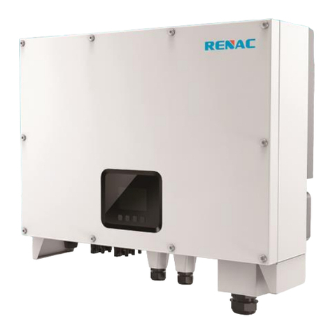
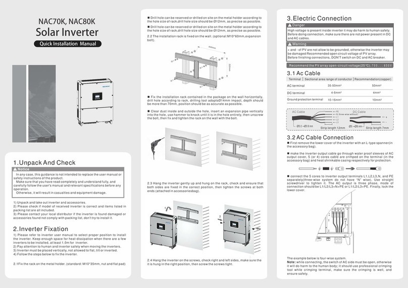
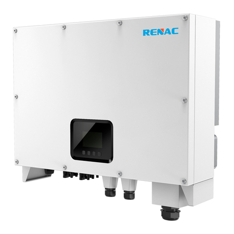
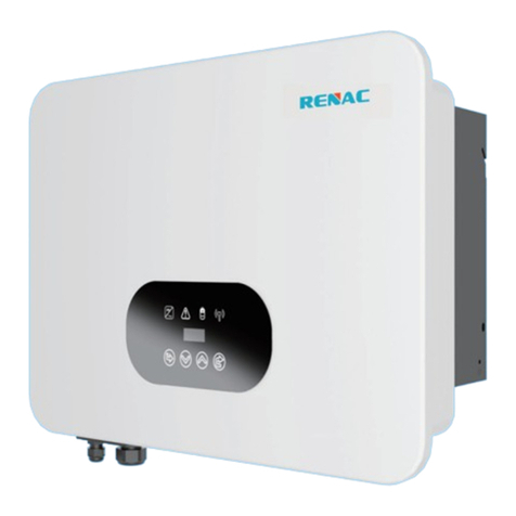
Renac R3 Navo Series User manual

R3-30K
R3-36K
R3-40K
R3-50K
User Manual
Series
R3 Navo

1. Introduction 2
1.1 Introduction 2
1.2 Applied designations 2
1.3 Important safety information 3
1.4 System sizing 3
2. Technical description of inverters 4
2.1 Mechanical design 4
2.2 Electrical system design 5
2.3 Technical data 5
2.4 Grid codes 6
3. Installation and startup 8
3.1 Package information 8
3.2 Installation environment 8
3.3 Installation position 9
3.4 Mounting procedure 10
3.5 Electrical connection 11
3.6 Starting the Inverter 15
4. User Interface 15
4.1 Led and key 15
4.2 LCD display 16
4.3 Factory setting 16
4.4 Setting language 17
4.5 Setting modbus address 17
4.6 Self-Test in accordance with CEI 0-21 (Applies to Italy only) 17
5. Warranty 19
5.1 Warranty claim procedure 19
5.2 Service after warranty expiration 20
Appendix A: FAQ (Frequently asked questions) 20
Content

R3 Navo Series User Manual2 3R3 Navo Series User Manual
1.2 Applied designations
1. Introduction
This manual describes solar inverters :
R3-30K / R3-36K / R3-40K / R3-50K.
These inverters are transformerless based inverter.
1.3 Importantsafety information
1.4 System sizing
1.1 Introduction
Before installation:
Installation:
Disconnecting the inverter:
Operating the inverter:
should be used.
Functional safety parameters:
When dimensioning a photovoltaic system, it must be ensured that the open
circuit voltage of the PV string never exceeds the maximum permissible
input voltage of 1100V DC. The PV string open circuit voltage during parallel
string operation is 1000V. Higher voltages may result in permanent damage
to the inverter.

R3 Navo Series User Manual4 5R3 Navo Series User Manual
2. Technical description of inverters
2.1 Mechanicaldesign
Figure 2-1Outline dimensions
Figure 2-2 wiring diagram of the inverter system
1
3
5
7
2
4
6
8
(Run/Fault)Key
2.2 Electricalsystem design
considered in each individual case.
2.3 Technical data
Model
PV Input Data
AC Output Data
45000
15000
200
3
2 / 2 / 2
30000
R3-30K R3-36K R3-40K R3-50K
Figure 2-1 shows the outline demensions of R3-30K/R3-36K/R3-40K/R3-50K:
1100
600
33000
180~1000
12 3 4 5
7
8
6
9
10
9 10Fans Ground terminal
Recommended Max. PV Power [Wp]
Max. PV power for single MPPT [Wp]
Max. PV Input Voltage [V]
MPPT Voltage Range [V]
Rated Input Voltage [V]
Start-up Voltage [V]
No. of MPP Trackers
No. of Input Strings per Tracker
Max. Input Current Per MPPT [A]
Max. Short-circuit Current per MPPT [A]
Rated AC Power [W]
Max. Output Power [VA]
Max. AC Current [A]
Rated AC Voltage / Range [V]
Grid Frequency / Range [Hz]
40 / 40 / 40
50 / 50 / 50
50
54000
15000
3
2 / 2 / 2
36000
39600
40 / 40 / 40
50 / 50 / 50
60
60000
15000
4
2 / 2 / 2 / 2
40000
44000
40 / 40 / 40 / 40
50 / 50 / 50 / 50
66.6
75000
20000
4
2 / 2 / 2 / 2
50000
55000
40 / 40 / 40 / 40
50 / 50 / 50 / 50
83.3
400; ±20%; 3 / PE or 3 / N / PE
50 / 60 ; ±5
Max. backfeed current to the array[A] 0
Maximum Output Overcurrent
Protection (A)
Inrush Current (Peak and Duration) (A)
Max. Output Fault Current
(Peak and Duration)(A)
50(3ms)
169
<3%
Adjustable Power Factor [cosφ]
Output THDi (@Rated Output)
0.8 leading ~ 0.8 lagging
250(8μs)
PV44

R3 Navo Series User Manual6 7R3 Navo Series User Manual
Protection
RD1699
Greece
G99
Brazil-180s
G98
Korea
Brazil
:
:
0
1
2
3
4
5
6
7
8
9
10
11
12
13
14
15
16
17
18
19
20
21
22
23
24
25
DescriptionNational/Regional Grid Code
No.
DC Switch
DC Insulation Monitoring
Input Reverse Polarity Protection
Anti-island Protection
Residual Current Monitoring
AC Overcurrent Protection
AC Short-circuit Protection
AFCI Protection
Anti-PID function
DC Surge Protection
AC Surge Protection
General Data
Size (Width * Height * Depth) [mm]
Weight [kg]
User Interface
Communication
Ambient Temperature Range [℃]
Relative Humidity
Operating Altitude [m]
Standby Self Consumption [W]
Topology
Cooling
Enclosure
Noise [dB]
Warranty [years]
585 * 480 * 220
37
LED + OLED
RS485 and USB or Wifi or 4G (Optional)
-25 ~ +60
0 ~ 100%
≤ 2000
< 1
Transformerless
IP65
< 60
5 / 7 / 10
Fan
Integrated
Integrated
Integrated
Integrated
Integrated
Integrated
Optional
Optional
Integrated (Type II)
Integrated
2.4 Grid codes
99.00%
98.50%
Eciency
Max. Eciency
Euro Eciency
99.00%
98.50%
99.00%
98.50%
99.00%
98.50%
Pollution Degree
Overvoltage Category
Protective class
Grid Regulation
Safety Regulation/EMC
VDE-AR-N4105, EN 50549
IEC 62109-1, IEC 62109-2/IEC 61000-6-1, EN 61000-6-3
Certifications & Standards
Ⅲ
DC Ⅱ/AC Ⅲ
Ⅰ

R3 Navo Series User Manual8 9R3 Navo Series User Manual
Tunisia
Tunisia-W
Brazil-W
Brazil-180s-W
: :
: :
: :
Tunisia
: :
26
27
28
29
30
31
32
33
34
35
36
37
38
39
40
41
42
43
44
45
46
47
48
49
50
DescriptionNational/Regional Grid Code
No.
3.1 Package information
3. Installation and startup
Figure 3-1 package information
3.2 Installation environment
Warning!
Note!
①
There are 6 PV+ connectors for R3-30K/36K; There are 8 PV+ connectors for R3-40K/50K.
②
There are 6 PV- connectors for R3-30K/36K; There are 8 PV- connectors for R3-40K/50K.
INVERTER*1
MOUNTING PANEL*1
PV CONNECTOR(+)
1
PV CONNECTOR(-)
2
GPRS/WIFI(OPTIONAL)
EXPANSION TUBE and SCREWS*4
QC PASS*1
合格证
型号:
检验员:
这是为了验证产品是否
符合交货条件
产品检验报告
产品
检验员:
1
2
3
4
5
6
7
8
9
10
测试项目:
通过
未通过
通过
通过
通过
通过
通过
通过
通过
通过
通过
通过
测试项目
生产日期
序列号 xxxx
xxxx xxxxxxxxx
xxxx
xxxx
xxxx
xxxx xxxxxxxxx
xxxx xxxxxxxxx
xxxx xxxxxxxxx
xxxx xxxxxxxxx
xxxx xxxxxxxxx
xxxx xxxxxxxxx
xxxx xxxxxxxxx
xxxx xxxxxxxxx
xxxx xxxxxxxxx
SCREW(M5X10)*1
TUBULAR TERMINAL(E25-22)*4
TUBULAR TERMINAL(E16-18)*3
AC WATERPROOF COVER*1
FACTORY REPORT*1
SCREW(M5*12)*1
GROUND TERMINAL*1

10 R3 Navo Series User Manual 11R3 Navo Series User Manual
3.3 Installation position
Figure 3-3Distance required of InvertorsFigure 3-4 mounting the inverter
Figure 3-2 installation position
Figure 3-2 installation environment
3.4 Mounting procedure
125.00 125.00
80.00

12 R3 Navo Series User Manual 13R3 Navo Series User Manual
3.5 Electricalconnection
3.5.1 Connection to the grid (AC output)
:15-25mm
16mm
50mm
6-15mm²
Remark
Protective layer
Description
B
D
No.
Figure 3-5 Strip off N/L1/L2/L3cables
current.
A
C
D
B
3) Passthe crimped AC wire into the AC connector.
4) The cables are inserted into the terminal according to
the wire sequence(L1/L2/L3/N/PE), so that the insulating
terminal is flush with the surface of theterminal, and the
crimping screw torque is 4.0 ± 0.1N·m.
5) Insert the main part of AC connector into
the terminal and hear a "click" sound.
6) Use a wrench to tighten the nut, and there is a
"click" sound.
7) Complete the installation.
2) Crimp N/L1/L2/L3 cables as figure:
PE
L1
L2
N
L3
PE
L1
L2
N
L3

R3 Navo Series User Manual14 R3 Navo Series User Manual 15
inverter.
3.5.2 Connection toPV string (DC input)
Disassembly the inverter from the Grid:
COM Port
12
I/O Port
USB
3.5.3 Communication connection
3.5.3.1 COM Port
Connect the WIFI/4G/GPRS module to the COM port of the inverter. After the connection is successful, you can view the inverter power
generation, operation status and other information through the mobile phone app. Please refer to the user manual of WIFI module for
details.
Relay
Meter -
RS 485 resistance
DRM0
C
G
N
DRM
Meter + RS 485- RS 485+
660.0
v

3.6 Starting the inverter
4. User interface
4.1 Led and key
Figure 4-1 LED display
Object Name
Indicator
LED
Button
LCD Screen Display the information of the inverter.
A
B
C
D
E
F
G
H
A
B
C
DEFG
H
R3 Navo Series User Manual16 R3 Navo Series User Manual 17
3.5.3.2 USB Port
Insert a USB flash disk for local software upgrade. Please contact after-sales personnel for details.
3.5.3.3 Meter connection
光伏组件
逆变器
电网
智能电表
负载
CTa连接到L1
CTb连接到L2
CTc连接到L3
电网
Renac R3 30-50kW series inverter has the function of anti reverse current, which can control the power exported to the grid by connecting an
intelligent electricity meter.
Note: The arrow on the CT must point to the grid.
3.5.3.3 RS 485 connection
Please refer to themodule user manual in detail.
Inverter Inverter Inverter
RS485 RS485
Internet
mobile terminal
RS485
GPRS/Wifi
PC
L N

4.2 LCD display
Mean Structure
R3 Navo Series User Manual18 R3 Navo Series User Manual 19
=====Solar=====
Vpv3: 0.0 V
Ipv3: 0.0/0.0A
Ppv3: 0 W
=====Solar=====
Vpv4: 0.0 V
Ipv4: 0.0/0.0A
Ppv4: 0 W
=====Solar=====
PV Conf: Comm
=====Grid=====
Va: 0.0 V
Ia: 0.0 A
=====Menu=====
>Status
History
Settings
=====Menu=====
Status
>History
Settings
====History====
>Yield Logs
Error Logs
===Yield Logs===
>Output Today
kWh
===Yield Logs===
>Output Total
kWh
====History====
Yield Logs
>Error Logs
===Error Logs===
01: xx-xx-xx
xx:xx:xx
XXX Fault
Normal
Power: W
XX-XX XX:XX:XX
=====Menu=====
Status
History
>Settings
====Settings====
>Language
Date&Time
PV Config
===Language===
>English
OK
To ‘Advanced*’
====Settings====
Language
>Date&Time
PV Config
===Date&Time===
Date:xx-xx-xx
Time:xx:xx:xx
OK
====Settings====
Language
Date&Time
>PV Config
===PV Config===
>Multi
OK
===PV Config===
>Comm
OK
====Settings====
Date&Time
PV Config
>Comm Addr
==Comm Addr==
>Local Addr
Meter Addr
===Local Addr===
>001
OK
==Comm Addr==
Local Addr
>Meter Addr
==Meter Addr==
>001
OK
=====Menu=====
History
Settings
>SysSwitch
===SysSwitch===
>Turn On
OK
===SysSwitch===
>Turn Off
OK
=====Menu=====
Settings
SysSwitch
>About
====About====
Model:
R3-50K
====About====
InverSN:
123456789abcdefg
====About====
M Ver: Vx.xx
S Ver: Vx.xx
H Ver: Vx.xx
=====TEMP=====
Inverter2: °C
Boost1: °C
=====Grid=====
Vc: V
Ic: A
=====Grid=====
Fac: Hz
Pac W
====Meter====
Pa: W
Pb: W
Pc: W
====Meter====
Ptotal: W
=====TEMP=====
Inner: °C
Inverter1: °C
=====Grid=====
Vb: V
Ib: A
====Settings====
Comm Addr
Key Mute
>Advanced*
====Settings====
PV Config
Comm Addr
>Key Mute
===Key Mute===
>Enable
OK
=====Solar=====
Vpv1: 0.0 V
Ipv1: 0.0/0.0A
Ppv1: 0W
=====Solar=====
Vpv2: 0.0 V
Ipv2: 0.0/0.0A
Ppv2: 0 W
==User Verify==
0000
OK
=====Settings=====
PV Config
Comm Addr
>Advanced*
====Safety====
>AS4777
OK
====On-Grid====
Safety
>Grid
Export Control
====On-Grid====
>Safety
Grid
Export Control
=====Grid=====
Volt Protect
>Freq Protect
=====Grid=====
>Volt Protect
Freq Protect
====On-Grid====
Safety
Grid
>Export Control
=Export Control=
>User Value
10000W
OK
=====USB=====
>Upgrade
====Upgrade====
>DSPM Upgrade
DSPS Upgrade
ARMC Upgrade
==DSPM Upgrade==
>No< Yes
====Upgrade====
DSPM Upgrade
>DSPS Upgrade
ARMC Upgrade
==DSPS Upgrade==
>No< Yes
====Upgrade====
DSPM Upgrade
DSPS Upgrade
>ARMC Upgrade
==ARMC Upgrade==
>No< Yes
=====Reset=====
>Reset Energy
Reset Errlogs
Factory Reset
===Advanced*===
Feature
New Password
>Reset
=====Reset=====
Reset Energy
>Reset Errlogs
Factory Reset
=Reset Errlogs=
>ESC< ENT
=====Reset=====
Reset Energy
Reset Errlogs
>Factory Reset
=Factory Reset=
>ESC< ENT
==Reset Energy==
>ESC< ENT
====Feature====
>Remote Control
DRM0
Meter Setting
=Remote Control=
>Disable
OK
====Feature====
Remote Control
>DRM0
Meter Setting
=====DRM0 =====
>Disable
OK
====Feature====
Remote Control
DRM0
>Meter Setting
===Advanced*===
On-Grid
>Feature
New Password
= =Meter Setting==
>Disable
OK
===Advanced*===
New Password
Rese
>USB
==Freq Protect==
>Fac Upper Fast
52.00Hz
OK
==Freq Protect==
>Fac Upper Slow
52.00Hz
OK
==Freq Protect==
>Fac Lower Slow
47.00Hz
OK
==Volt Protect==
>Vac Lower Fast
000.0V
OK
==Volt Protect==
>Vac Upper Slow
260.0V
OK
==Volt Protect==
>Vac Upper Fast
265.0V
OK
==Volt Protect==
>Vac Lower Slow
180.0V
OK
==Volt Protect==
>Vac 10M Avg
255.0V
OK
==Freq Protect==
>Fac Lower Fast
47.00Hz
OK
===Advanced*===
On-Grid
Feature
>New Password
==New Password==
Enter Password
0000
OK
Normal
Power: W
XX-XX XX:XX:XX
=====Menu=====
Status
History
>Settings
===Advanced*===
>On-Grid
Feature
New Password
==New Password==
Enter it again:
0000
OK
==New Password==
Enter it again:
0000
>Set Succeed
==New Password==
Enter it again:
0000
>Error, retry!
Mean Structure

R3 Navo Series User Manual 21R3 Navo Series User Manual20
4.2.1 Setting language
Normal
Power: W
XX-XX XX:XX:XX
=====Menu=====
Status
History
>Settings
====Settings====
>Language
Date&Time
PV Config
===Language===
>English
OK
4.2.2 Setting date&time
Normal
Power: W
XX-XX XX:XX:XX
=====Menu=====
Status
History
>Settings
====Settings====
Language
>Date&Time
PV Config
===Date&Time===
Date:xx-xx-xx
Time:xx:xx:xx
OK
4.2.3 Setting PV configuration
4.2.4 Setting communication address
4.2.5 Setting safety
4.2.6 Setting export control
Normal
Power: W
XX-XX XX:XX:XX
=====Menu=====
Status
History
>Settings
====Settings====
Language
Date&Time
>PV Config
===PV Config===
>Multi
OK
===PV Config===
>Comm
OK
Normal
Power: W
XX-XX XX:XX:XX
=====Menu=====
Status
History
>Settings
====Settings====
Date&Time
PV Config
>Comm Addr
==Comm Addr==
>Local Addr
Meter Addr
===Local Addr===
>001
OK
==Comm Addr==
Local Addr
>Meter Addr
==Meter Addr==
>001
OK
==User Verify==
0000
OK
=====Settings=====
PV Config
Comm Addr
>Advanced*
====Safety====
>AS4777
OK
====On-Grid====
>Safety
Grid
Export Control
Normal
Power: W
XX-XX XX:XX:XX
=====Menu=====
Status
History
>Settings
===Advanced*===
>On-Grid
Feature
New Password
==User Verify==
0000
OK
=====Settings=====
PV Config
Comm Addr
>Advanced*
====Feature====
Remote Control
DRM0
>Meter Setting
===Advanced*===
On-Grid
>Feature
New Password
= =Meter Setting==
>Disable
OK
Normal
Power: W
XX-XX XX:XX:XX
=====Menu=====
Status
History
>Settings
Step1: Enable the meter setting first.
Step 2: Setting the power exported to the grid.
==User Verify==
0000
OK
=====Settings=====
PV Config
Comm Addr
>Advanced*
====On-Grid====
Safety
Grid
>Export Control
=Export Control=
>User Value
10000W
OK
===Advanced*===
>On-Grid
Feature
New Password
4.2.7 Upgrading the inverter
4.2.8 Facotry reset
4.2.9 Error logs
4.2.10 Error logs
==User Verify==
0000
OK
=====Settings=====
PV Config
Comm Addr
>Advanced*
=====USB=====
>Upgrade
====Upgrade====
>DSPM Upgrade
DSPS Upgrade
ARMC Upgrade
==DSPM Upgrade==
>No< Yes
====Upgrade====
DSPM Upgrade
>DSPS Upgrade
ARMC Upgrade
==DSPS Upgrade==
>No< Yes
====Upgrade====
DSPM Upgrade
DSPS Upgrade
>ARMC Upgrade
==ARMC Upgrade==
>No< Yes
===Advanced*===
New Password
Rese
>USB
Normal
Power: W
XX-XX XX:XX:XX
=====Menu=====
Status
History
>Settings
Step 1: Please contact Renac technicians to obtain the upgrade program.
Step 2: Insert the USB disk into the computer and copy the upgrade program to the USB disk.
Step 3: Insert the USB disk into the USB port of the inverter.
Step 4: Refer to the above figure to upgrade DSPM, DSPS and ARMC respectively.
Step 5: After the upgrade, the inverter will start to work automatically.
==User Verify==
0000
OK
=====Settings=====
PV Config
Comm Addr
>Advanced*
=====Reset=====
>Reset Energy
Reset Errlogs
Factory Reset
===Advanced*===
Feature
New Password
>Reset
=====Reset=====
Reset Energy
>Reset Errlogs
Factory Reset
=Reset Errlogs=
>ESC< ENT
=====Reset=====
Reset Energy
Reset Errlogs
>Factory Reset
=Factory Reset=
>ESC< ENT
==Reset Energy==
>ESC< ENT
Normal
Power: W
XX-XX XX:XX:XX
=====Menu=====
Status
History
>Settings
=====Menu=====
Status
>History
Settings
====History====
>Yield Logs
Error Logs
====History====
Yield Logs
>Error Logs
===Error Logs===
01: xx-xx-xx
xx:xx:xx
XXX Fault
Normal
Power: W
XX-XX XX:XX:XX
=====Menu=====
Settings
SysSwitch
>About
====About====
Model:
R3-12K
====About====
InverSN:
123456789abcdefg
====About====
M Ver: Vx.xx
S Ver: Vx.xx
H Ver: Vx.xx
Normal
Power: W
XX-XX XX:XX:XX

R3 Navo Series User Manual22 R3 Navo Series User Manual 23
5. Warranty
5.1 Warranty claim procedure
4.6 Self-Test in accordance with CEI 0-21 (Applies to Italy only)
==User Verify==
0000
OK
=====Settings=====
PV Config
Comm Addr
>Advanced*
====Safety====
>CEI0-21
OK
====On-Grid====
>Safety
Grid
Export Control
===Advanced*===
>On-Grid
Feature
New Password
=====Menu=====
Status
History
>Settings
Normal
Power: W
XX-XX XX:XX:XX
====On-Grid====
Grid
Export Control
>Self Test
There are two ways to execute the self-test(You need to set the inverter country to CEI 0-21 before testing).
Auto-Test from screen:
5.2 Service after warranty expiration
Appendix A: FAQ (Frequently asked questions)
Inverter
Solar Admin
COM
COM1
History info
Protection other
CEI
AUTOTEST
Italy Autotest
1987
Pass
199
Pass
195.5
1486
Pass
34.5
186
Pass Pass
Fmin 49.8 49.94
Pass
51.5
98
Pass
Fmin
89
Pass
Read
Product Model (e.g.R3-12K) and the Serial Number(e.g.8700831201211006).

R3 Navo Series User Manual24 R3 Navo Series User Manual 25
Possible actions
LCD display
Fault ID
1
3
4
5
6
7
8
9
11
Grid Lost Fault
SW OCP Fault
GFCI Fault
The isolation is failed.
Possible actions
LCD display
Fault ID
19
20
21
22
23
24
25
26
Inv EEPROM Fault
AD Sample Fault
Arc Device Fault
GFCI HW Fault
Relay M1 Short
Relay M2 Short
Relay Open
F Consist Fault
Grid Volt Fault
Vgrid 10M Fault
Grid Freq Fault
Pv Volt Fault
Bus Volt Fault
DCI OCP Fault
Temp Fault
Iso Check Fault
Ground Fault
The inverter is not connected to the ground.
Please check if the ground connection is normal,then reconnect.
Or seed help from us,if not go back to normal state.
Meter Lost Fault
13
14
15
16
17
18
Anti-PID
PLL Error
Island Error
SCI Fault
Fan Device Fault
Fan Fault
Grid Flashover
Relay S1 Short
Relay S2 Short
OtherDeviceFault
V Consist Fault
AuxVolt Error
I Consist Fault
RC Consist Fault
SCI Fault
HMI EEPROM Fault
27
28
29
30
31
32
33
34
35
36
The errors are internal faults of Renac inverte
•Turn off PV and grid,wait for 5 mins,then reconnect.
•Or seek help from us, if not go back to normal state.
The communication between meter and Inverter is interrupted.
• Check if the communication cable between meter and lnverter
is correctly and wellconnected.
The errors are internal faults of Renac inverte
•Turn off PV and grid,wait for 5 mins,then reconnect.
•Or seek help from us, if not go back to normal state.
The errors are internal faults of Renac inverte
•Turn off PV and grid,wait for 5 mins,then reconnect.
•Or seek help from us, if not go back to normal state.
The errors are internal faults of Renac inverte
•Turn off PV and grid,wait for 5 mins,then reconnect.
•Or seek help from us, if not go back to normal state.
The errors are internal faults of Renac inverte
•Turn off PV and grid,wait for 5 mins,then reconnect.
•Or seek help from us, if not go back to normal state.
The errors are internal faults of Renac inverte
•Turn off PV and grid,wait for 5 mins,then reconnect.
•Or seek help from us, if not go back to normal state.
The errors are internal faults of Renac inverte
•Turn off PV and grid,wait for 5 mins,then reconnect.
•Or seek help from us, if not go back to normal state.

422-00050-00
R E N A C P O W E R T ECHNO L O G Y C O . , LT D .
Block C-12, No. 20 Datong Road, Comprehensive Bonded Zone, Suzhou Hi-Tech District, Suzhou, China
Tel:+86-0512-66677278
info@renacpower.com
www.renacpower.com
SMART ENERGY FOR BETTER LIFE
6.1 Routine Maintenance
Period
the inverter enclosure if necessary. Check if the air inlet
if necessary.
the metal enclosure.
LCD display
System clean
Cable entry
Electrical Connection
Item
Once a year
Maintenance Instruction
•
NOTICE
R3 Navo Series User Manual26
6. Maintenance
This manual suits for next models
4
Table of contents
Other Renac Inverter manuals

Renac
Renac R1 Kiddy Series User manual

Renac
Renac R3-10K-LV User manual

Renac
Renac ESC Series User manual

Renac
Renac R3 Pro NAC20K-DT User manual

Renac
Renac NAC70K Operating and maintenance instructions
Renac
Renac N3-HV Series User manual

Renac
Renac A1-HV Series User manual

Renac
Renac R3 LV Series User manual

Renac
Renac R3 Micro Series User manual
Renac
Renac N1-HV Series User manual