Renac R1 Kiddy Series User manual

0

1
Contents
1.Introduction...........................................................................................................................................................2
1.1 Introduction....................................................................................................................................................2
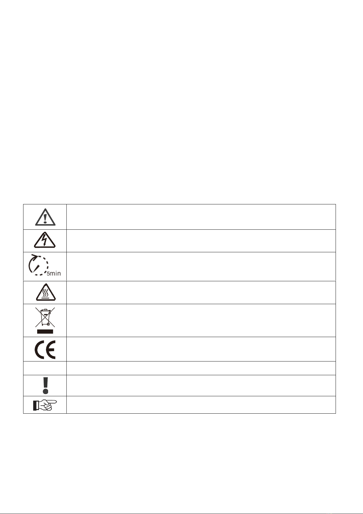
1.2. Applied designations....................................................................................................................................2
1.3. Important safety information.........................................................................................................................3
1.4. System sizing...............................................................................................................................................3
2. Technical description of inverters.......................................................................................................................4
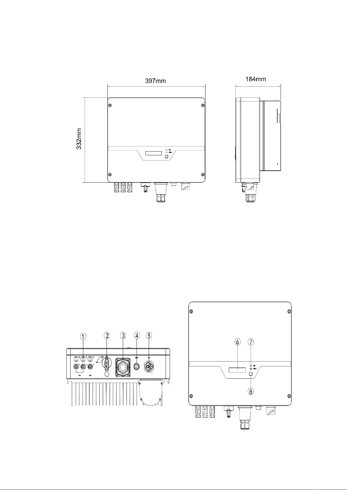
2.1. Mechanical design........................................................................................................................................ 4
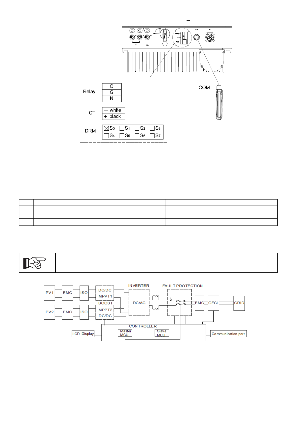
2.2. Electrical system design...............................................................................................................................5
2.3. Technical data..............................................................................................................................................6
2.4. Grid codes....................................................................................................................................................7
3. Installation and startup........................................................................................................................................8
3.1. Package information.....................................................................................................................................8
3.2. Installation environment ...............................................................................................................................8
3.3. Installation position.......................................................................................................................................9
3.4. Mounting procedure ...................................................................................................................................10
3.5. Electrical connection ..................................................................................................................................11
3.6. Starting the inverter....................................................................................................................................14
4. User interface....................................................................................................................................................14
4.1. Led and key................................................................................................................................................14
4.2. LCD display................................................................................................................................................15
4.3. Factory setting............................................................................................................................................15
4.4. Setting language ........................................................................................................................................16
4.5. Setting modbus address ............................................................................................................................16
4.6. Setting export power (CT)..........................................................................................................................16
4.7. Self-Test in accordance with CEI 0-21 (Applies to Italy only)....................................................................16
5. Warranty............................................................................................................................................................18
5.1. Warranty claim procedure..........................................................................................................................18
5.2. Service after warranty expiration................................................................................................................18
Appendix A: FAQ (Frequently asked questions)...................................................................................................19

2
1.Introduction
1.1 Introduction
This manual describes solar inverters: NAC4K-DS/NAC5K-DS/NAC6K-DS/NAC7K-DS/NAC8K-DS.
These inverters are transformerless based inverter.
Please read the safety instructions in this manual first. Throughout the manual it is assumed that the reader is
familiar with AC and DC installations and knows the rules and regulations for electrical equipment and for
connecting it to the utility AC grid. It is especially important to be familiar with the general safety rules for
working with electrical equipment.
1.2 Applied designations
Throughout the manual important information is shown at different levels depending on the character of the
information, as shown here:
Safety information important for human safety. Violation of warnings may result in injury to
persons or death.
Danger of high voltage and electric shock!
Signals danger due to electrical shock and indicates the time (5 minutes) to allow after the
inverter has been turned off and disconnected to ensure safety in any installation operation.
Danger of hot surface!
Product should not be disposed as normal household waste.
CE Mark
RoHS
ROHS Mark
Information important for the protection of property. Violation of this type of information may
cause damage and loss of property.
Useful additional information or “Tips and Tricks” on specific subjects.

3
1.3 Important safety information
Read this before installing, operating or maintaining the inverter.
1.4 System sizing
When dimensioning a photovoltaic system, it must be ensured that the open circuit voltage
of the PV string never exceeds the maximum permissible input voltage of 600V DC. The PV
string open circuit voltage during parallel string operation is 550V. Higher voltages may
result in permanent damage to the inverter.
The selection of PV string output should be based on the optimum utilization of the invested capital compared
to the expected annual energy yield from the system. This optimization depends on local weather conditions
and should be considered in each individual case.
The inverter incorporates an input power limiting device, which automatically keeps the power at levels that are
safe for the inverter. The limitation depends mainly on internal and ambient temperatures. The limitation is
calculated continuously and always allows the maximum possible amount of energy to be produced.
Please use the tool supplied by Renac Power when dimensioning a photovoltaic system.
Before installation:
Check for damage to inverter and packaging. If you are in doubt, please contact your
supplier before installing the inverter. Check the voltages of the solar modules and make
sure they are within the limits of the inverter specifications before connecting them to the
inverter.
Installation:
Only trained and authorized personnel familiar with local electrical codes may install the
inverter. For optimum safety, please follow the steps described in this manual. Keep in mind
that the inverter has two voltage carrying sides, the PV input and the AC grid.
Disconnecting the inverter:
Always disconnect the AC line first! Afterwards disconnect the PV lines. Note that the
inverter can still be charged with very high voltages at hazardous levels even when it is
disconnected from grid and solar modules. Wait at least 5 min. before proceeding, after
having disconnected from grid and PV panels.
Operating the inverter:
Before connecting the AC grid to the inverter, make sure that the installation cover is
mounted again. The inverter must not be open during operation.
Maintenance and modification:
Only authorized personnel are allowed to repair or modify the inverter. To ensure optimum
safety for user and environment, only the original spare parts available from your supplier
should be used.
Functional safety parameters:
Unauthorized changes of functional safety parameters may cause injury or accidents to
people or inverter. Additionally it will lead to the cancelling of all inverter operating approval
certificates.

4
2. Technical description of inverters
2.1 Mechanical design
Figure 2-1 shows the outline dimensions of NAC4K-DS/NAC5K-DS/NAC6K-DS/NAC7K-DS/NAC8K-DS:
Figure 2-1 Outline dimensions
Figure 2-2 shows the electrical terminals of NAC4K-DS/NAC5K-DS/NAC6K-DS/NAC7K-DS/NAC8K-DS:

5
Figure 2-2 Electrical Terminals
Remark:
For CEI standard, DRM S0 is the DI port, corresponding to PIN5 (GND), PIN6 (DI input port) of RJ45.
1
DC (PV terminal)
2
DC Switch
3
I/O Port
4
Communication port
5
AC terminal
6
LCD
7
LEDs (Run/Fault)
8
Key
2.2 Electrical system design
Figure 2-3 wiring diagram of the inverter system
Please refer to chapter 3 for the detail connecting and install methods.
For safety reasons, the use of a DC switch is recommended. Between the PV modules and
the power modules may be mandatory in some countrie

6
2.3 Technical data
Model
NAC4K
-DS
NAC5K
-DS
NAC6K
-DS
NAC7K
-DS
NAC8K
-DS
DC Input Data
Max. Recommended PV Power
5200Wp
6500Wp
7800Wp
9100Wp
10400Wp
Max.DC Input Voltage
600V
MPPT voltage Range
100-550V
Start-up Voltage
120V
No. of MPP Trackers
2
No. of Input Strings per Tracker
1/1
2/1
Max. DC Input Current (A)
12.5 / 12.5
12.5 / 12.5
12.5 / 12.5
20 / 12.5
20 / 12.5
DC Switch
Optional
AC Output Data
Rated AC Power
4000W
5000 W
6000W
7000 W
8000 W
Max.output power
4400VA
5500VA
6600VA
7700VA
8000VA
Max. AC Current
19.2 A
24 A
28.7 A
33.5 A
34.8 A
Rated AC Voltage/Range
220V/230V; 160-290V
Grid frequency/ range
50Hz/60Hz ; ±5Hz
Adjustable Power Factor[cos φ]
0.8leading ~0.8lagging
Output THDi(@Rated Output)
≤2%
Efficiency
Max.Efficiency
97.8%
97.8%
97.8%
98.1%
98.1%
Euro Efficiency
97.2%
97.2%
97.2%
97.5%
97.5%
MPPT Efficiency
99.9%
99.9%
99.9%
99.9%
99.9%
Protection
DC Insulation Monitoring
Integrated
Input Reverse Polarity Protection
Integrated
Anti-island Protection
Integrated
Residual Current Monitoring
Integrated
Over-heat Protection
Integrated
AC Overcurrent Protection
Integrated
AC Short-circuit Protection
Integrated
AC Overvoltage Protection
Integrated
DC Surge Protection
Integrated(Type III)
AC Surge Protection
Integrated(Type III)
General Data
Size(Width*Height*Depth)
395x330x185mm
Weight
12KG
12KG
12KG
16KG
16KG
User Interface
LCD
Communication
RS485(Standard), Wifi or GPRS
Ambient Temperature Range
-25 ℃~ 60 ℃
Relative Humidity
0-100%
Operating Altitude
≤4000m
Standby Self Consumption
<0.2W
Topology
Transformerless
Cooling
Natural Convection
Protection Grades
IP65
Noise
<30dB
Warranty
5 /7/10 years
Certifications & Standards
Grid Regulation
VDE-AR-N-4105, VDE 0126-1-1, PEA, AS4777, EN50549,NB/T
32004-2013,CEI0-21,EC61727,IEC62116,IEC60068,IEC61683,ABNT
Safety Regulation
IEC 62109-1, IEC 62109-2
EMC
EN 61000-6-1, EN 61000-6-2, EN 61000-6-3, EN 61000-6-4,EN 61000-
4-16, EN 61000-4-18, EN 61000-4-29

7
2.4 Grid codes
No.
National/Regional Grid Code
Description
1
VDE4105-DE
Germany power Grid, meet Grid standards “VDE-AR-N-4105”.
2
CEI0-21
Italy power Grid.
3
AS4777
Australia power Grid.
4
RD1699
Spain power Grid.
5
EN50549-TR
Turkey power Grid.
6
EN50549-DK
Denmark power Grid.
7
Greece
Greece power Grid.
8
EN50549-NL
Netherland power Grid, meet Grid standards “EN50438”.
9
C10/11
Belgium power Grid.
10
G59
UK power Grid.
11
China
China power Grid, meet Grid standards “CN-NBT”.
12
VDE0126-FR
France power Grid, meet Grid standards “VDE 0126”.
13
EN50549-PL
Poland power Grid.
14
BDEW-DE
Germany power Grid, meet Grid standards “BDEW-MV”.
15
VDE0126-DE
Germany power Grid, meet Grid standards “VDE 0126”.
16
CEI0-16
Italy power Grid, meet Grid standards “CEI 0-16”.
17
G83
UK power Grid.
18
Greece Island
Greece Island power Grid.
19
EN50549-CZ
Czech Republic power Grid, meet Grid standards
“EN50438Y2007-CZ”.
20
IEC61727
India power Grid.
21
Korea
Korea power Grid.
22
EN50549-SW
Sweden power Grid.
23
China-W
China power Grid, Grid voltage range:160-290V
Grid frequency range:47-53HZ.
24
China-H
China power Grid, meet standards“CQC ”.
25
IEC61727-IN
India power Grid, meet Grid standards “IEC61727”.
26
Brazil
Brazil power Grid , meet Grid standards “NBT 16150”.
27
IEC61727-SL
Sri Lanka power Grid, meet Grid standards “IEC61727”.
28
Mexico
Mexico power Grid, meet Grid standards “IEC61727 60HZ”.
29
NZ4777
New Zealand power Grid, meet Grid standards “NZ4777”.
30
Philippines
Philippines power Grid, meet Grid standards “IEC61727 60HZ
spec”.
31
IEC61727-SL-W
Sri Lanka power Grid, Grid voltage range:160-290V, Grid
frequency range:47-53HZ.
32
PEA
Thailand power Grid.
33
PEA-W
Thailand power Grid, Grid voltage range:160-290V, Grid
frequency range:47-53HZ.
34
IEC61627-VN
Vietnam power Grid.
35
IEC61627-VN-W
Vietnam power Grid, Grid voltage range:160-290V, Grid
frequency range:47-53HZ.

8
3. Installation and startup
Warning!
Before installation and maintenance, AC and DC side doesn’t carry electricity, but if DC side
is just disconnected, capacitance still contains electricity, so please wait for at least 5
minutes to ensure the capacitors completely release the energy and inverter is not
electrified.
Note!
Inverters must be installed by qualified person.
3.1 Package information
①There are 2 PV+ connectors for NAC4/5/6K-DS and 3 PV connectors for NAC7/8K-DS
②There are 2 PV- connectors for NAC4/5/6K-DS and 3 PV connectors for NAC7/8K-DS
Figure 3-1 package information
3.2 Installation environment
1) In order to achieve optimal performance, the ambient temperature should be kept lower than 45 °C.
2) For the convenience of checking the LCD display and possible maintenance activities, please install the
inverter at eye level.
3) Inverters should NOT be installed near inflammable or explosive items. Any strong electro-magnetic
equipment should be kept away from installation site.
4) Product label and warning symbol shall be clear to read after installation.

9
5) Please do not install inverter under direct sunlight, rain and snow.
Figure 3-2 installation environment
3.3 Installation position
1) The installation method and mounting location must be suitable for the inverter's weight
and dimensions.
2) Mount on a solid surface.
3) Select a well-ventilated place sheltered from direct sun radiation.
Figure 3-3 installation position
In consideration of heat dissipation and convenient dismantlement, the minimum clearances around the
inverter should be no less than the following value:
Figure 3-4 Distance required of Invertors

10
3.4 Mounting procedure
Setp1: Drill 4 Fix Ø11 holes in the wall according to the dimensions.
Step2: Fix the wall mounting bracket on the wall with 4 expansion bolts in accessory bag.
Setp4: Place the inverter on the wall-mounted bracket and install the fix screw.
Figure 3-5 mounting the inverter

11
3.5 Electrical connection
3.5.1 Connection to the grid (AC output)
1) Add breaker or fuse to AC side, the specification should be more than 1.25 times of rated
AC output current.
2) The PE line of inverter should be connected to the earth, make sure the impedance of
neutral wire and earth wire less than 10 ohm.
3) Disconnect the breaker or fuse between the inverter and the utility.
4) All inverters incorporate a certified internal Residual Current Device(RCD) in order to
protect against possible electrocution and fire hazard in case of a malfunction in the PV
array, cables or inverter.There are 2 trip thresholds for the RCD as required for certification
(IEC 62109-2:2011). The default value for electrocution protection is 30mA, and for slow
rising current is 300mA.
Connect the inverter to the grid as follows:
1. Strip off L/N/PE cables as figure 3-5:
No.
Description
Remark
A
Protective layer
Diameter ranges :9-16mm
B
Length of stripped off
12mm
C
Insulate layer
50mm
D
Cross section of ac cables
6-10mm²
Figure 3-6 Strip off PE/N/L cables
2. Tighten the nut clockwise & Tighten L/N/PE cable screws to the terminals according to markings.
Fix (Torque: 2~2.5 N.m) the connector of AC cable to the corresponding terminals
Figure 3-7 Connect the inverter to the Grid
3. Plug Grid side connector into AC connector of inverter end, rotate and tighten clockwise.
A
C
D
B

12
3.5.2 Connection to PV string (DC input)
1) Before connecting PV string, make sure DC switch is turned off
2) Make sure PV string polarity confirms with DC connector, otherwise, it will cause
damage to inverter
3) Make sure the maximum open circuit voltage (Voc) of each PV string does not exceed
the inverter input voltage Vmax under any condition
4) Do not connect positive or negative pole of PV string to earth wire. Otherwise, it will
cause damage to inverter
Figure 3-8 Connect the PV string

13
3.5.3 RS485 communication
1) Please make sure the RS485 connecting cables not exceed 1000m.
2) Communication lines must be separated from other power lines to avoid
communications interference.
Remark: RS485 port, PIN3: A, PIN4:B. Figure 3-9 RS485 Port
Figure 3-10 RS485 in multiple series
Figure 3-11 install WIFI/GPRS module
Please refer to the module user manual in detail.

14
3.6 Starting the inverter
Before turn on the inverter, please confirm:
1) Three AC wires (PE/L/N) cable correctly connected to the inverter AC side through AC circuit breaker;
2) The DC cable connected correctly to the inverter DC side through DC circuit breaker, please be attention
to the cable connected to the two string correctly and it’s polarity;
3) The unused terminals are covered.
Starting the inverter:
Step1: Close the DC and AC circuit breaker;
Step2: If the solar panels provide enough energy, the power module will work and the LCD panel will be
lit;
Step3: In case you are starting the inverter for the first time, the inverter needs to be commissioned.
Commissioning is described on page 16, chapter 4.3
Step4: Then the inverter will turn into self-check mode and the LCD panel will display the remaining time
of connect simultaneously;
Step5: After the inverter turn into normal mode, it feeds electrical energy into grid, and LCD panel will
display the generated electrical energy.
As long as the inverter works, it will automatically track the maximum power point to absorb the maximum
energy from solar. When night comes, the irradiance is not strong enough to provide energy, the inverter will
power off automatically. When the next day comes, the input voltage reaches the start value, it will start again
automatically.
4. User interface
4.1 Led and key
Figure 4-1 LED display
No.
Object
Description
1
Run
(Green LED)
On = Normal operation
Flashing = Waiting, checking or starting up
2
Fault
(Red LED)
On = Failure
Flashing = Temporary failure
3
Pushbutton
Pressing < 1 s: Next
Pressing > 2 s: Enter

15
4.2 LCD display
Menu structure:
Normal/fault
Power:W
Vpv1:V
Power:W
Ipv2:A
Power:W
Vac A:V
Power:W
Iac A:A
Power:W
Fac:Hz
Power:W
E-today:KwH
Power:W
E-total:KwH
Power:W
SN NO.
Moudle
Firmware
M: ×.×× S:×.××
Country
××××××
Event list
Power:W
Setting
Power:W
Fault code1
Power:W
Language setting
Power:W
Country setting
Power:W
...
Power:W
...
Power:W
User setting Factory setting
Language
Factory setting
Country setting
Factory setting
Module Add
xx
PF setting
Power:W
Clear events
Power:W
Factory setting
Power:W
Clear E-total
Power:W
PF:xxx
Power:W
Setting Add
Pac = W
中文
Factory setting
English
Factory setting
VDE4105
Factory setting
中国2
Factory setting
...
Factory setting
Fault code ...
Power:W
...
Power:W
...
Power:W
Factory setting
Power:W
xx
Pac = W
Auto test
Pac = W ...
Power:W
4.3 Factory setting
1) Press pushbutton long in order to enter the “Factory setting” menu.
2) Press pushbutton long to enter the “language setting” menu.
3) Press pushbutton less than 1 sec. to the langue menu you want and Press pushbutton long to select.
4) Press pushbutton less than 1 sec. to the country menu you want and Press pushbutton long to select.

16
4.4 Setting language
1) Press pushbutton less than 1 sec. several times until you reach the “Setting” menu.
2) Press pushbutton long in order to enter the “setting” menu.
3) Press pushbutton less than 1 sec. several times until you reach the “language setting” menu.
4) Press pushbutton less than 1 sec. to the langue menu you want and Press pushbutton long to select.
4.5 Setting modbus address
1) Press pushbutton less than 1 sec. several times until you reach the “Setting” menu.
2) Press pushbutton long in order to enter the “setting” menu.
3) Press pushbutton less than 1 sec. several times until you reach the “module add” menu.
4) Press pushbutton less than 1 sec. to the modbus address number you want and Press pushbutton long
to set.
4.6 Setting export power (CT)
1) Press pushbutton less than 1 sec. several times until you reach the “Setting” menu.
2) Press pushbutton long in order to enter the “setting” menu.
3) Press pushbutton less than 1 sec. several times until you reach the “Export power” menu.
4) Press pushbutton long to enter onto “Export power”.
5) Set “Export power” as “1”, press pushbutton long to save the value.
4.7 Self-Test in accordance with CEI 0-21 (Applies to Italy only)
The self-test is only required for inverters, which are commissioned in Italy. The Italian standard requires that
all inverters feeding into the utility grid are equipped with a self-test function in accordance with CEI 0-21.
During the self-test, the inverter will consecutively check the protection reaction times and values for
overvoltage, under voltage, over frequency and under frequency.
Self-test function is available at any time. It also allows end user get test reports shown on LCD display.
There are two ways to execute the self-test:
Auto-Test from screen:
1) Press pushbutton less than 1 sec. several times until you reach the “Setting” menu.
2) Press pushbutton long in order to enter the “setting” menu.
3) Press pushbutton less than 1 sec. several times until you reach the “AutoTest-Italy” menu (You need to
set the inverter country to CEI 0-21 before testing).
4) Press pushbutton long to execute the auto-test.
5) The inverter will automatically run the test until the screen shows “Test end”, if the test passes, it will
show “test ok”, if the test is failed, it will show “test failed”.

17
Auto-Test from Solar Admin:
1) Download and install “Solar Admin” on laptop.
2) Connect inverter to laptop via RS485 port.
3) When the inverter and “solar admin” are successfully connected. Click “Sys.setting” - “Other” -
“AUTOTEST” enter into “Auto-Test” interface.
4) Click “Execute” to start the test.
5) The inverter will automatically run the test until the screen shows “Test end”.
6) Click "Read" to read the test value, and click "Export" to export the test report.
7) After click “Read” button, interface will show the test results, if the test passes, it will show “PASS”, if the
test is failed, it will show “FAIL”.

18
5. Warranty
The standard warranty period for the inverter is 60 months from the date of installation and no more than 66
months (5.5 years) from the date of shipment from factory.
5.1 Warranty claim procedure
Please report defective device with a brief error description and SN code to our service mail or service hotline
for registration.
Alternatively, please contact your specific dealer or installer if your unit is defective or faulty.
To claim the warranty under the warranty terms of factory, you need to supply us with the following information
and documentation regarding the faulty unit:
1) Product Model No ( e.g. NAC-8K-DS) and the serial Number (e.g. 8000831190511006).
2) Copy of the invoice and warranty certificate for the inverter.
3) Error message on LCD screen and additional information regarding the fault/error.
4) Detailed information about the entire system (modules, circuits, etc.).
5) Documentation of previous claim/exchanges ( if applicable).
In the case of an exchange, the remainder of the warranty entitlement will be transferred to the replacement
device. In this event, you will not receive a new certificate, as this replacement will be noted by factory.
5.2 Service after warranty expiration
For products which are out of warranty, factory charges an on-site service fee, parts, labor cost and logistic fee
to end-user which can be any/all of:
1) On-site attendance fee: Cost of travel and time for the technician in attending on-site;
2) Parts: Cost of replacement parts (including any shipping/admin fee that may apply);
3) Labor: Labor time fee charged for the technician, who is repairing, maintaining, and installing (hardware
or software) and debugging the faulty product;
4) Logistic fee: Cost of delivery, tariff and other derived expense when defective products are sent from
user to factory or/and repaired products are sent from factory to user;

19
Appendix A: FAQ (Frequently asked questions)
Sometimes, the PV system does not work normally; we recommend the following solutions for average
troubleshooting. This can help the technician to understand the problem and take a proper action.
Fault
LCD display
Possible actions
Clearable Fault
Isolation Fault1
Isolation Fault2
1. Check whether the inverter is earthed and test impedance
between PV (+) & (-) and the impedance must exceed
3MΩ;
2. Check whether the AC-side has contacts with earth.
Grid Faults:
10min OVR
Fault OVR
Fault UVR
Fault OFR
Fault UFR
1. Wait for 5 minutes, if the grid returns to normal, PV inverter
automatically restarts.
2. Make sure grid voltage and frequency meet the local
specifications.
No utility
1. Grid is not connected.
2. Check grid connection cables.
3. Check grid usability.
4. If grid is ok and the problem exists still, maybe the fuse in the
inverter is open, please call service.
Low Temp
Over Temp
1. The internal temperature of inverter is higher or lower than
specified normal value.
2. Find a way to reduce or increase the ambient temperature.
3. if the problem remains, please call local service
PV over Voltage:
PV1OVFault
PV2OVFault
1. Check the open PV DC voltage, and see if it is greater than
or too close to 550VDC
2. If PV DC voltage is less than 550VDC, and the problem still
occurs, please call local service.
Permanent Fault
Consistent Faults:
Consist VGrid
Consist Freq
Consist GFCI
Consist DCI
1. Disconnect all PV (+) or PV (-) from solar panels
2. Wait for a few seconds.
3. After the LCD switches off, reconnect and check again.
4. If the problem remains, please call local service.
RelayFail
EEPROM R/W Fail
Sci Comm lose
Spi Comm lose
BusHFault
GFCIDeviceFault
IGridDevice
PLLFault
AutoTestFail
PV Config fault
Fan error
DCI out range
OCPV1
OCPV2
OCIGrid
This manual suits for next models
5
Table of contents
Other Renac Inverter manuals

Renac
Renac R3-10K-LV User manual

Renac
Renac R3 Pro NAC20K-DT User manual

Renac
Renac N1 HL Series User manual

Renac
Renac N3-HV Series User manual

Renac
Renac R3 Micro Series User manual

Renac
Renac R3 Navo Series User manual

Renac
Renac R3 LV Series User manual

Renac
Renac Pre R3 Series User manual

Renac
Renac A1-HV Series User manual

Renac
Renac R3 Micro Series User manual
Popular Inverter manuals by other brands

Xantrex
Xantrex GT100-208 Operation and maintenance manual

Pyle
Pyle PNV2000 owner's manual

Mitsubishi Electric
Mitsubishi Electric FR-A7AP instruction manual

Gooloo
Gooloo GTX280-Y user manual

Sensata
Sensata ADI-300/3000D owner's manual

YASKAWA
YASKAWA SOLECTRIA XGI 1500-250/250-600 Installation and operation guide