Renac R3 Pro NAC20K-DT User manual

0

1
Content
1. Introduction.........................................................................................................................................................2
1.1 Introduction...................................................................................................................................................2
1.2 Applied designations...................................................................................................................................2
1.3 Important safety information......................................................................................................................2
1.4 System sizing...............................................................................................................................................3
2. Technical description of inverters ...................................................................................................................3
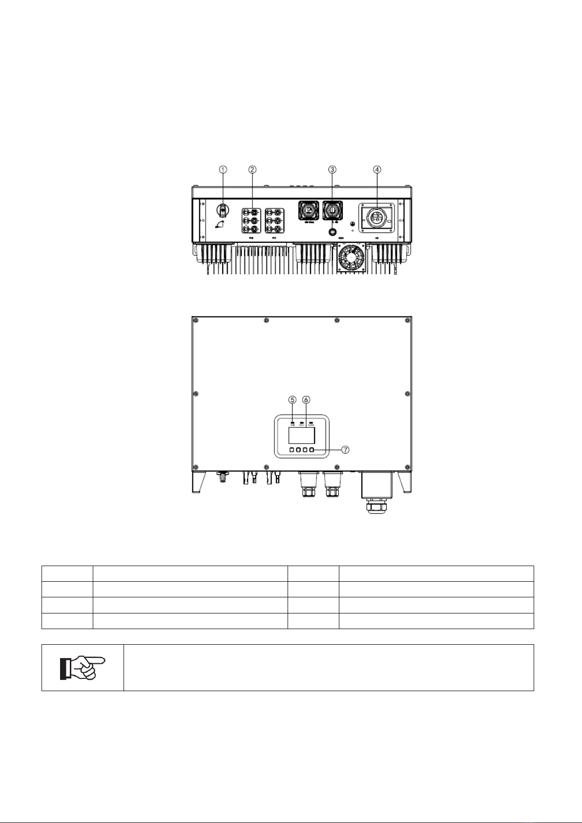
2.1 Mechanical design ......................................................................................................................................3
2.2 Electrical system design.............................................................................................................................5
2.3 Technical data..............................................................................................................................................5
2.4 Grid codes....................................................................................................................................................6
3. Installation and startup......................................................................................................................................7
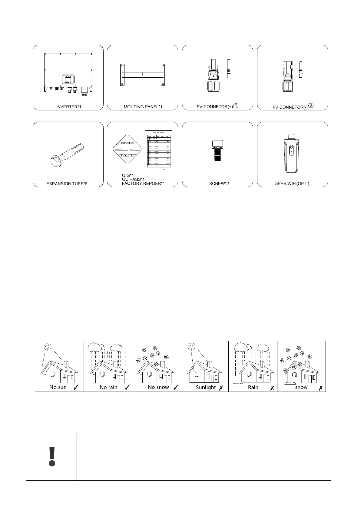
3.1 Package information...................................................................................................................................8
3.2 Installation environment .............................................................................................................................8
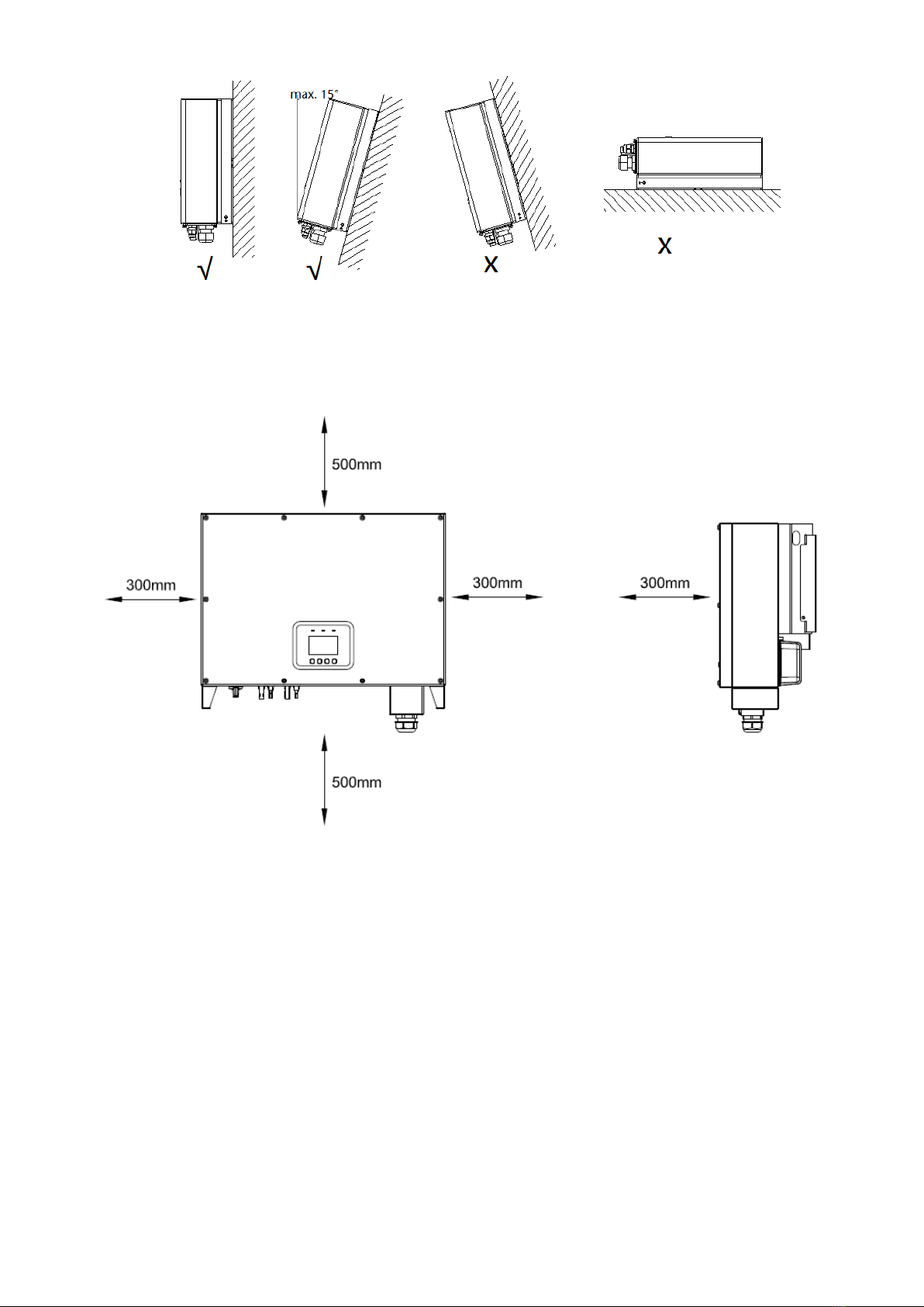
3.3 Installation position......................................................................................................................................8
3.4 Mounting procedure....................................................................................................................................9
3.5 Electrical connection.................................................................................................................................11
3.6 Starting the Inverter ..................................................................................................................................14
4. User Interface...................................................................................................................................................15
4.1 Led and key................................................................................................................................................15
4.2 LCD display................................................................................................................................................16
5. Warranty ...........................................................................................................................................................17
5.1 Warranty claim procedure........................................................................................................................17
5.2 Service after warranty expiration ............................................................................................................17
Appendix A: FAQ (Frequently asked questions).............................................................................................18

2
1. Introduction
1.1 Introduction
This manual describes solar inverters:
NAC20K-DT/NAC25K-DT/NAC30K-DT/NAC33K-DT.
These inverters are transformerless based inverter.
Please read the safety instructions in this manual first. Throughout the manual it is assumed that the reader is
familiar with AC and DC installations and knows the rules and regulations for electrical equipment and for
connecting it to the utility AC grid. It is especially important to be familiar with the general safety rules for
working with electrical equipment.
1.2 Applied designations
Throughout the manual important information is shown at different levels depending on the character of the
information, as shown here:
Safety information important for human safety. Violation of warnings may result in injury
to persons or death.
Information important for the protection of property. Violation of this type of information
may cause damage and loss of property.
Useful additional information or “Tips and Tricks" on specific subjects.
1.3 Important safety information
Read this before installing, operating or maintaining the inverter.
Before installation:
Check for damage to inverter and packaging. If you are in doubt, please contact your
supplier before installing the inverter. Check the voltages of the solar modules and make
sure they are within the limits of the inverter specifications before connecting them to the
inverter.
Installation:
Only trained and authorized personnel familiar with local electrical codes may install the
inverter. For optimum safety, please follow the steps described in this manual. Keep in
mind that the inverter has two voltage carrying sides, the PV input and theAC grid.
Disconnecting the inverter:
Always disconnect the AC line first! Afterwards disconnect the PV lines. Note that the
inverter can still be charged with very high voltages at hazardous levels even when it is
disconnected from grid and solar modules. Wait at least 5 min. before proceeding, after
having disconnected from grid and PV panels.
Operating the inverter:
Before connecting the AC grid to the inverter, make sure that the installation cover is

3
mounted again. The inverter must not be open during operation.
Maintenance and modification:
Only authorized personnel are allowed to repair or modify the inverter. To ensure
optimum safety for user and environment, only the original spare parts available from
your supplier should be used.
Functional safety parameters:
Unauthorized changes of functional safety parameters may cause injury or accidents to
people or inverter. Additionally it will lead to the cancelling of all inverter operating
approval certificates.
1.4 System sizing
When dimensioning a photovoltaic system, it must be ensured that the open circuit
voltage of the PV string never exceeds the maximum permissible input voltage of 1000V
DC. The PV string open circuit voltage during parallel string operation is 950V. Higher
voltages may result in permanent damage to the inverter.
The selection of PV string output should be based on the optimum utilization of the invested capital compared
to the expected annual energy yield from the system. This optimization depends on local weather conditions
and should be considered in each individual case.
The inverter incorporates an input power limiting device, which automatically keeps the power at levels that are
safe for the inverter. The limitation depends mainly on internal and ambient temperatures. The limitation is
calculated continuously and always allows the maximum possible amount of energy to be produced.
Please use the tool supplied by Renac Power when dimensioning a photovoltaic system.
2. Technical description of inverters
2.1 Mechanical design
Figure 2-1 shows the outline dimensions of NAC20K-DT/NAC25K-DT/NAC30K-DT/NAC33K-DT.
Figure 2-1 Outline dimensions

4
Figure 2-2 shows the electrical terminals of NAC20K-DT/NAC25K-DT/NAC30K-DT/NAC33K-DT.
Figure 2-2 Electrical Terminals
1
DC Switch
2
DC (PV terminal)
3
Communication port
4
AC terminal
5
LEDs
6
Display screen
7
Keys
For safety reasons, the use of a DC switch is recommended. Between the PV modules
and the power modules may be mandatory in some countries.

5
2.2 Electrical system design
Figure 2-3 wiring diagram of the inverter system
Please refer to chapter 3 for the detail connecting and install methods.
2.3 Technical data
Model
NAC20K-DT
NAC25K-DT
NAC30K-DT
NAC33K-DT
DC Input Data
Max. Recommended PV Power
26000Wp
32500Wp
39000Wp
42900Wp
Max.DC Input Voltage
1000V
MPPT voltage Range
250-950V
Start-up Voltage
350V
No. of MPP Trackers
2
No. of Input Strings per Tracker
2/2
2/3
3/3
3/3
Max. DC Input Current
20A/20A
20A/30A
30A/30A
30A/30A
DC Switch
Integrated
AC Output Data
Rated AC Power
20000W
25000W
30000W
33000W
Max.output power
22000VA
27600VA
30000VA
33000VA
Max. AC Current
32A
40A
43A
48A
Rated AC Voltage/Range
3/PE 380, 400;+/-10%; 3/N/PE 380, 400;+/-10%;
Grid frequency/ range
50Hz/60Hz ; ±5Hz
Adjustable Power Factor[cos φ]
0.8leading ~0.8lagging
Output THDi(@Rated Output)
<3%
Efficiency
Max.Efficiency
98.30%
98.40%
98.50%
98.50%
Euro Efficiency
98.00%
98.10%
98.20%
98.20%
MPPT Efficiency
99.90%
99.90%
99.90%
99.90%
Protection
DC Insulation Monitoring
Integrated
Input Reverse Polarity Protection
Integrated
Anti-island Protection
Integrated

6
Residual Current Monitoring
Integrated
Over-heat Protection
Integrated
AC Overcurrent Protection
Integrated
AC Short-circuit Protection
Integrated
AC Overvoltage Protection
Integrated
DC Surge Protection
Integrated(Type II)
AC Surge Protection
Integrated(Type II)
General Data
Size(Width*Height*Depth)
660×460×255mm
Weight
38KG
User Interface
LCD
Communication
RS485(Standard), Wifi or GPRS
Ambient Temperature Range
-25 ℃~ 60 ℃
Relative Humidity
0-100%
Operating Altitude
≤4000m
Standby Self Consumption
<0.2W
Topology
Transformerless
Cooling
Natural
Convection
Natural
Convection
Natural
Convection
Fan Cooling
Protection Grades
IP65
Noise
<35dB
Warranty
5 /7/10 years
Certifications & Standards
Grid Regulation
VDE-AR-N-4105, VDE 0126-1-1, PEA, AS4777, EN50549,NB/T
32004-2013,CEI0-21,IEC61727,IEC62116,IEC60068,IEC61683
Safety Regulation
IEC 62109-1, IEC 62109-2
EMC
EN 61000-6-1, EN 61000-6-2, EN 61000-6-3, EN 61000-6-4,
EN 61000-4-16, EN 61000-4-18, EN 61000-4-29
2.4 Grid codes
No.
National/Regional Grid Code
Description
1
VDE4105-DE
Germany power Grid, meet Grid standards “VDE-AR-N-4105”.
2
CEI0-21
Italy power Grid.
3
AS4777
Australia power Grid.
4
RD1699
Spain power Grid.
5
EN50549-TR
Turkey power Grid.
6
EN50549-DK
Denmark power Grid.
7
Greece
Greece power Grid.
8
EN50549-NL
Netherland power Grid, meet Grid standards “EN50438”.
9
C10/11
Belgium power Grid.
10
G59
UK power Grid.
11
China
China power Grid, meet Grid standards “CN-NBT”.
12
VDE0126-FR
France power Grid, meet Grid standards “VDE 0126”.
13
EN50549-PL
Poland power Grid.

7
14
BDEW-DE
Germany power Grid, meet Grid standards “BDEW-MV”.
15
VDE0126-DE
Germany power Grid, meet Grid standards “VDE 0126”.
16
CEI0-16
Italy power Grid, meet Grid standards “CEI 0-16”.
17
G83
UK power Grid.
18
Greece Island
Greece Island power Grid.
19
EN50549-CZ
Czech Republic power Grid, meet Grid standards
“EN50438Y2007-CZ”.
20
IEC61727
India power Grid.
21
Korea
Korea power Grid.
22
EN50549-SW
Sweden power Grid.
23
China-W
China power Grid, Grid voltage range:160-290V, Grid frequency
range:47-53HZ.
24
China-H
China power Grid, meet standards”CQC”.
25
IEC61727-IN
India power Grid, meet Grid standards “IEC61727”.
26
Brazil
Brazil power Grid , meet Grid standards “NBT 16150”.
27
IEC61727-SL
Sri Lanka power Grid, meet Grid standards “IEC61727”.
28
Mexico
Mexico power Grid, meet Grid standards “IEC61727 60HZ”.
29
NZ4777
New Zealand power Grid, meet Grid standards “NZ4777”.
30
Philippines
Philippines power Grid, meet Grid standards “IEC61727 60HZ
spec”.
31
IEC61727-SL-W
Sri Lanka power Grid, Grid voltage range:160-290V, Grid
frequency range:47-53HZ.
32
PEA
Thailand power Grid.
33
PEA-W
Thailand power Grid, Grid voltage range:160-290V, Grid
frequency range:47-53HZ.
34
IEC61627-VN
Vietnam power Grid.
35
IEC61627-VN-W
Vietnam power Grid, Grid voltage range :160-290V, Grid
frequency range:47-53HZ.
3. Installation and startup
Warning!
Before installation and maintenance, AC and DC side doesn’t carry electricity, but if DC
side is just disconnected, capacitance still contains electricity, so please wait for at least
5 minutes to ensure the capacitors completely release the energy and inverter is not
electrified.
Note!
Inverters must be installed by qualified person.

8
3.1 Package information
①There are 4 PV+ connectors for NAC20K-DT 、5 PV+ connectors for NAC25K-DT and 6 PV+connectors for
NAC30/33K-DT
②There are 4 PV- connectors for NAC20K-DT 、5 PV- connectors for NAC25K-DT and 6 PV-connectors for
NAC30/33K-DT
Figure 3-1 Package information
3.2 Installation environment
1)In order to achieve optimal performance, the ambient temperature should be kept lower than 45 °C.
2)For the convenience of checking the LCD display and possible maintenance activities, please install the
inverter at eye level.
3)Inverters should NOT be installed near inflammable or explosive items. Any strong electro-magnetic
equipment should be kept away from installation site.
4)Product label and warning symbol shall be clear to read after installation.
Please do not install inverter under direct sunlight, rain and snow.
Figure 3-2 installation environment
3.3 Installation position
1) The installation method and mounting location must be suitable for the inverter's
weight and dimensions.
2) Mount on a solid surface.
3) Select a well-ventilated place sheltered from direct sun radiation.

9
Figure 3-3 installation position
In consideration of heat dissipation and convenient dismantlement, the minimum clearances around the
inverter should be no less than the following value
Figure 3-4 Distance required of Invertors
3.4 Mounting procedure
Setp1: Drill 4 Fix Ø10 holes in the wall according to the dimensions.
Step2: Fix the wall mounting bracket on the wall with 4 expansion bolts in accessory bag.
Setp4: Place the inverter on the wall-mounted bracket and install the fix screw.

10
Figure 3-5 mounting the inverter

11
3.5 Electrical connection
3.5.1 Connection to the Grid (AC output)
1) Add breaker or fuse toAC side, the specification should be more than 1.25 times of
rated AC output current.
2) The PE line of inverter should be connected to the earth, make sure the impedance
of neutral wire and earth wire less than 10 ohm.
3) Disconnect the breaker or fuse between the inverter and the utility.
4) The integrated leakage current detection device of the inverter can detect external
leakage current in real time. When the detected leakage current exceeds the limit
value, inverter will quickly disconnect with the grid. If the leakage current protection
device is installed externally, the action current should be 300mA or higher.
Connect the inverter to the Grid as follows:
1. Strip off N/L1/L2/L3 cables as figure 3-5:
A
C
D
B
No.
Description
Remark
A
Protective layer
Diameter ranges :22-27mm
B
Length of stripped off
15mm
C
Insulate layer
-
D
Cross section of ac cables
10-16mm²
Figure 3-5 Strip off N/L1/L2/L3 cables
2. Strip off PE cable as figure 3-6
Figure 3-6 Strip off PE cables
3. Insert AC cables through cable gland from outside, Pull the cables through and fix N/L1/L2/L3/PE cables.
ends to the terminals according to markings
Fix (Torque: 2~2.5 N.m) the connector ofAC cable to the corresponding terminals.

12
Figure 3-7 Connect the inverter to the grid
4. Screw waterproof coupling and Screw cap nut tightly onto the cable.
3.5.2. Connection to PV string (DC input)
1) Before connecting PV string, make sure DC switch is turned off
2) Make sure PV string polarity confirms with DC connector, otherwise, it will cause
damage to inverter
3) Make sure the maximum open circuit voltage (Voc) of each PV string does not
exceed the inverter input voltage Vmax under any condition
4) Do not connect positive or negative pole of PV string to earth wire. Otherwise, it will
cause damage to inverter
Figure 3-8 Connect the PV string

13
3.5.3. RS485/ Relay/DI
Figure 3-9 communication interfaces
Figure 3-10 RS485 in multiple series
Please make sure the RS485 connecting cables not exceed 1000m.
Communication lines must be separated from other power lines to avoid communication
interference.

14
3.5.4. WIFI/GPRS communication
By the WIFI/GPRS interface, transfer the inverter power output information,
alarm information, operation state to the PC terminal or local data acquisition device.
Figure 3-11 install WIFI/GPRS module
Remark:
1)COM port, PIN3:A, PIN4:B.
2)For how to monitor system through WIFI/GPRS, please refer to the module user manual in detail.
3.6 Starting the Inverter
Before turn on the inverter, please confirm:
1)Three phase five wires (PE/L1/L2/L3/N) cable correctly connected to the inverter AC side through AC
circuit breaker;
2)The DC cable connected correctly to the inverter DC side through DC circuit breaker, please be attention
to the cable connected to the two string correctly and it’s polarity;
3)The unused terminals are covered.
Starting the inverter:
Step1: Close the DC andAC circuit breaker;
Step2: If the solar panels provide enough energy, the power module will work and the LCD panel will be.
lit;
Step3: In case you are starting the inverter for the first time, the inverter needs to be commissioned.
Commissioning is described on page 17, chapter 4.3;
Step4: Then the inverter will turn into self-check mode and the LCD panel will display the remaining. Time.
of connecting simultaneously;

15
Step5: After the inverter turn into normal mode, it feed electrical energy into grid, and LCD panel will.
display the generated electrical energy;
As long as the inverter works, it will automatically track the maximum power point to absorb the maximum
energy from solar. When night comes, the irradiance is not strong enough to provide energy, the inverter will
power off automatically. When the next day comes, the input voltage reaches the start value, it will start again
automatically;
4. User Interface
4.1 Led and key
Figure 4-1 LED display
No
Name
Description
1
ESC Button
ESC Operation, Leave from current interface or function.
2
Up Button
Up Operation, Move cursor to upside or increase value.
3
Down Button
Down Operation, Move cursor to downside or decrease value.
4
Enter Button
Enter Operation, confirm the selection.
5
Run (Green LED)
Green LED is on, Normal working Status.
6
Fault (Red LED)
Red LED is on, fault.
7
Warning (Yellow LED)
Yellow LED is on, Warning.

16
4.2 LCD display
Menu structure:
Real-time data History data System setting
Event record
Tem info
Input mode
Total energy
Twelev Yield
Menu settings
Date time setting
Language setting
Grid info
Input Password
Serial number
Firmware update
Recovery setting
String info
Day Yield
PV info
Inverter type
DSP M SW
MCU-H SW
DSP S SW
SFLASH_FS Init
Clear energy
Clear record
Month Yield
Year Yield
System safety
Communication
System restart
Confbox setting
StdRS485-mode
Export limit
Grid setting
Device info

17
5. Warranty
The standard warranty period for the inverter is 60 months from the date of installation and no more than 66
months (5.5 years) from the date of shipment from factory.
5.1 Warranty claim procedure
Please report defective device with a brief error description and SN code to our service mail or service hotline
for registration.
Alternatively, please contact your specific dealer or installer if your unit is defective or faulty.
To claim the warranty under the warranty terms of factory, you need to supply us with the following information
and documentation regarding the faulty unit:
Product Model No ( e.g. NAC-20K-DT) and the serial Number (e.g. 8122031190902002).
Copy of the invoice and warranty certificate for the inverter.
Error message on LCD screen and additional information regarding the fault/error.
Detailed information about the entire system (modules, circuits, etc.).
Documentation of previous claim/exchanges ( if applicable).
In the case of an exchange, the remainder of the warranty entitlement will be transferred to the replacement
device. In this event, you will not receive a new certificate, as this replacement will be noted by factory.
5.2 Service after warranty expiration
For products which are out of warranty, factory charges an on-site service fee, parts, labor cost and logistic fee
to end-user which can be any/all of:
On-site attendance fee: Cost of travel and time for the technician in attending on-site;
Parts: Cost of replacement parts (including any shipping/admin fee that may apply);
Labor: Labor time fee charged for the technician, who is repairing, maintaining, and installing (hardware or
software) and debugging the faulty product;
Logistic fee: Cost of delivery, tariff and other derived expense when defective products are sent from user to
factory or/and repaired products are sent from factory to user;

18
Appendix A: FAQ (Frequently asked questions)
Sometimes, the PV system does not work normally; we recommend the following solutions for average
troubleshooting. This can help the technician to understand the problem and take a proper action.
Fault
LCD display
Possible actions
Clearable Fault
PVIsoFault
1. Check whether the inverter is earthed and test impedance
between PV (+) & (-) and the impedance must exceed
3MΩ;
2. Check whether the AC-side has contacts with earth.
Ground I Fault
1. The ground current is too high or GND connection problem
2. After cutting off the AC side connection, unplug the inputs
from the PV generator and check the peripheralAC
system.
3. After the cause is cleared, re-plug the PV panel and AC
connection, and check PV inverter status.
GridOVP
GridUVP
GridOFR
GridUFR
1. Wait for 5 minutes, if the grid returns to normal, PV inverter
automatically restarts.
2. Make sure grid voltage and frequency meet the local
specifications.
No Utility
1. Grid is not connected.
2. Check grid connection cables.
3. Check grid usability.
4. If grid is ok and the problem exists still, maybe the fuse in
the inverter is open, please call service.
Over Temperature:
INV OV Temp
BST OV Temp
AMB OV Temp
1. The internal temperature of inverter is higher than specified
normal value.
2. Find a way to reduce the ambient temperature. Or move
the inverter to a cooler environment.
3. If the problem remains, please call local service.
PV1OVP
PV2OVP
PV3OVP
PV4OVP
1. Check the open PV DC voltage, and see if it is greater than
or too close to 950VDC
2. If PV DC voltage is less than 950VDC, and the problem still
occurs, please call local service.
PV1UVP
PV2UVP
PV3UVP
PV4UVP
1. Check the open PV DC voltage, and see if it is less than
250VDC
2. If PV DC voltage is more than 250VDC, and the problem
still occurs, please call local service.
Ph Seq fault
1. Check the phase sequence if it is correct, if not, please
correct the phase sequence.
2. If the phase sequence is correct, and the problem still
occurs, please call local service.
Permanent Fault
Consistent Vac
Consistent Fac
Consistent GFCI
Consistent DCI
1. Disconnect all PV (+) or PV (-) from solar panels.
2. Wait for a few seconds.
3. After the LCD switches off, reconnect and check again.
4. If the problem remains, please call local service.
Relay failure

19
Permanent Fault
GFDI fault
1. Disconnect all PV (+) or PV (-) from solar panels.
2. Wait for a few seconds.
3. After the LCD switches off, reconnect and check again.
4. If the problem remains, please call local service.
HMI to S fail
M to S fail
HMI to Cfail
HwAcOCP
SwAcOCP
uSwAcOCP
SwOCP_PV1-4
HwOCP_BST1-4
UHwOCP_BST
HwBusOVP
uHwBusOVP
BusUVP
BusOVP
PLL fault
BusVolt_Ublc
IacRms_Ublc
VacRms_Ublc
DciOCP
GFCI>30mA
GFCI>60mA
GFCI>150mA
GFCI>300mA
GFCI>5 times
uHw_GFCI
Fan alarm
RChipFault
MChipFault
HMIChipFault
Ctl EEPROM Wr
Ctl EEPROM Rd
HMI EEPROM Wr
HMI EEPROM Rd
RefVFault
RTCW fault
HwSPS1Fault
HwSPS2Fault
HwM_ADVGrid
HwM_ADVInv
HwM_ADIGrid
HwM_AD_DCI
HwM_AD_GFCI
HwS_ADVGrid
HwS_ADVInv
HwS_ADIGrid
HwS_AD_DCI
HwS_AD_GFCI
This manual suits for next models
3
Table of contents
Other Renac Inverter manuals

Renac
Renac R3 Navo Series User manual

Renac
Renac ESC Series User manual

Renac
Renac Pre R3 Series User manual

Renac
Renac R3 Micro Series User manual

Renac
Renac R3 LV Series User manual

Renac
Renac R3 Micro Series User manual

Renac
Renac R1 Kiddy Series User manual

Renac
Renac A1-HV Series User manual

Renac
Renac N3-HV Series User manual

Renac
Renac N1-HV Series User manual
Popular Inverter manuals by other brands

Conrad
Conrad 12V/160W operating instructions

Homelite
Homelite HGCA5700 series Operator's manual

National Instruments
National Instruments PXIe-5413 Calibration manual

DEWESOFT
DEWESOFT DS-GPS-CLOCK Technical reference manual

Icel Manaus
Icel Manaus GV-2005 user manual

Omron
Omron SYSDRIVE MX2 SERIES user manual