manuals.online logo
Brands
  1. Home
  2. •
  3. Brands
  4. •
  5. Renesas
  6. •
  7. Motherboard
  8. •
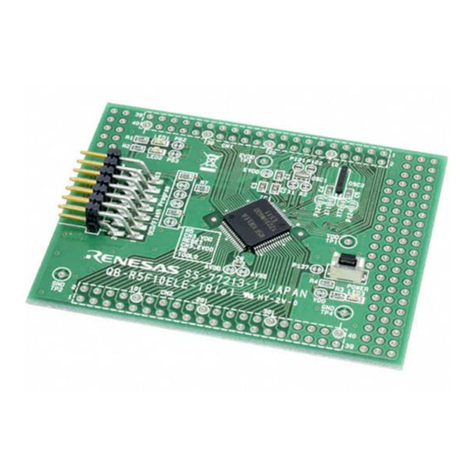
  9. Renesas QB-R5F10Y16-TB User manual

Renesas QB-R5F10Y16-TB User manual

Other Renesas Motherboard manuals

Renesas ISL9241EVAL1Z User manual

Renesas

Renesas ISL9241EVAL1Z User manual

Renesas EK-RA6M1 User manual

Renesas

Renesas EK-RA6M1 User manual

Renesas ISL81802EVAL3Z User manual

Renesas

Renesas ISL81802EVAL3Z User manual

Renesas EU045 User manual

Renesas

Renesas EU045 User manual

Renesas RX63N-256KB User manual

Renesas

Renesas RX63N-256KB User manual

Renesas Intersil ISL28133EVAL1Z User manual

Renesas

Renesas Intersil ISL28133EVAL1Z User manual

Renesas RTK0EMX270S01020BJ User manual

Renesas

Renesas RTK0EMX270S01020BJ User manual

Renesas RH850/F1x User manual

Renesas

Renesas RH850/F1x User manual

Renesas ISL68134-31P-EV1Z Setup guide

Renesas

Renesas ISL68134-31P-EV1Z Setup guide

Renesas ISL68201-99140DEMO1Z User manual

Renesas

Renesas ISL68201-99140DEMO1Z User manual

Renesas RX23W Series User manual

Renesas

Renesas RX23W Series User manual

Renesas ISL68137-61P-EV1Z User manual

Renesas

Renesas ISL68137-61P-EV1Z User manual

Renesas Y-RH850-F1X-176PIN-PB-T1-V3 User manual

Renesas

Renesas Y-RH850-F1X-176PIN-PB-T1-V3 User manual

Renesas ISL8560EVAL2Z User manual

Renesas

Renesas ISL8560EVAL2Z User manual

Renesas ISL6225EVAL2 User manual

Renesas

Renesas ISL6225EVAL2 User manual

Renesas DA9063 User manual

Renesas

Renesas DA9063 User manual

Renesas RA4 Series User manual

Renesas

Renesas RA4 Series User manual

Renesas FS3000 Pmod User manual

Renesas

Renesas FS3000 Pmod User manual

Renesas Synergy TB-S3A6 User manual

Renesas

Renesas Synergy TB-S3A6 User manual

Renesas Y-G-HYBRID-PLC-RF User manual

Renesas

Renesas Y-G-HYBRID-PLC-RF User manual

Renesas EK-RA6E2 User manual

Renesas

Renesas EK-RA6E2 User manual

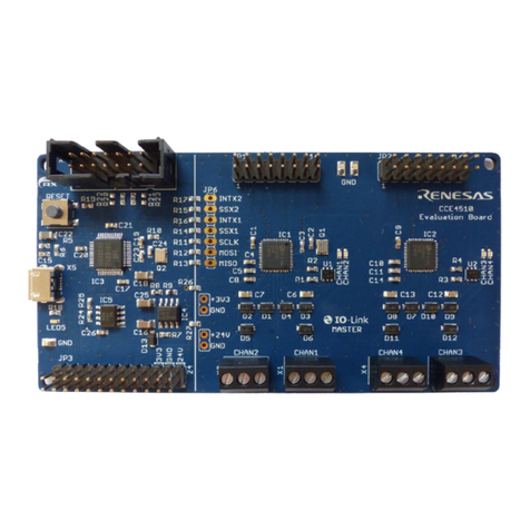
Renesas CCE4510 User manual

Renesas

Renesas CCE4510 User manual

Renesas CCE4503 User manual

Renesas

Renesas CCE4503 User manual

Renesas RH850/D1x Instructions for use

Renesas

Renesas RH850/D1x Instructions for use

Popular Motherboard manuals by other brands

Gigabyte MNJ190I-FH user manual

Gigabyte

Gigabyte MNJ190I-FH user manual

Biostar HI-FI-Z87X-3D Setup manual

Biostar

Biostar HI-FI-Z87X-3D Setup manual

Atmel SAM9753PIA-DK user guide

Atmel

Atmel SAM9753PIA-DK user guide

Coapt GEN2 Handbook

Coapt

Coapt GEN2 Handbook

Supero SUPER P4DL6 user manual

Supero

Supero SUPER P4DL6 user manual

Cypress CY3210-PSoCEVAL1 quick start guide

Cypress

Cypress CY3210-PSoCEVAL1 quick start guide

ASROCK B660M-HDV manual

ASROCK

ASROCK B660M-HDV manual

Fujitsu D2831 Short description

Fujitsu

Fujitsu D2831 Short description

Industrial Computers ADE-6050 user manual

Industrial Computers

Industrial Computers ADE-6050 user manual

Asus TUF Z270 MARK 2 manual

Asus

Asus TUF Z270 MARK 2 manual

DFI NB71-BC user manual

DFI

DFI NB71-BC user manual

ASROCK H61 Pro BTC user manual

ASROCK

ASROCK H61 Pro BTC user manual

Norco POS-7893 user manual

Norco

Norco POS-7893 user manual

Intel DG965MS specification

Intel

Intel DG965MS specification

Asus B85M-VIEW PAKER user manual

Asus

Asus B85M-VIEW PAKER user manual

Asus P5G41T-M LX V2 user manual

Asus

Asus P5G41T-M LX V2 user manual

Gigabyte GA-K8VT800-RH user manual

Gigabyte

Gigabyte GA-K8VT800-RH user manual

Gigabyte Z790M AORUS ELITE user manual

Gigabyte

Gigabyte Z790M AORUS ELITE user manual

manuals.online logo
manuals.online logoBrands
  • About & Mission
  • Contact us
  • Privacy Policy
  • Terms and Conditions

Copyright 2025 Manuals.Online. All Rights Reserved.

RL78/G10 ターゲット・ボード
QB-R5F10Y16-TB ユーザーズ・マニュアル
ユーザーズ・マニュアル
R20UT2349XJ0200
Rev 2.00 2013.06.24
本製品は、ルネサス エレクトロニクス製のプログラミング機能付きオンチップ・デバッグ・エミュレータ E1 を使用して、マイコンの動作を試
すためのターゲット・ボードです。
①RL78/G10 ターゲット・ボード(QB-R5F10Y16-TB)の特徴
●RL78/G10(R5F10Y16)搭載
●ユニバーサル・エリア(2.54mm ピッチ)を搭載
●フラッシュ・メモリ・プログラミング, オンチップ・デバッグのみ対応(TOOL0 端子使用)
●マイコンの端子を周辺ボード・コネクタに配置した高拡張性
●基板を切り離すことで, 2.54 ㎜ DIP ピッチに変換した基板として使用可能
●鉛(Pb)フリー対応品
②ハードウエア仕様
CPU R5F10Y16 メイン・クロック動作周波数 最大 20MHz
搭載部品
CN1,CN2,CN4: 周辺ボードコネクタ(2.54mm ピッチ) 5pin ソケット x3(パッドのみ)
CN3: 14pin コネクタ(E1 接続用)
Power LED: 赤 x1(LED2)
LED: 黄 x1(LED1 は P00 へ接続)
SW: SW1(INTP0 へ接続)
動作電圧 2.7V~5.5V (高速オンチップ・オシレータ 20MHz 動作時)
③寸法、部品配置など
SW1
P00
VDD
TOOL0
RESET
T_RESET
GND
VDD
SS-77226-1 QB-R5F10Y16
60mm
ユニバーサル
・エリア
LED
上:LED2(POWER)
下:LED1(P00)
14pinコネクタ
SW1(INTP0)
20mm
<TopView>
<BottomView>
VDD
GND
VDD
GND
T_RESET
RESET
TOOL0
JP1
JP2
JP3
JP4
OCD/Flash
Program
POWER
RESET
1
6
5
CN2
CN4
10
RL78/G10
GND
CN1
基板上のパターン について:パターンをカットすることで、その回路はオープンとなります。
再度接続させたい場合は半田ショートしてください。
P00 を使用する場合は LED の左のショートパッドをパターンカットしてください。
回路図のパッドの表示 オープン: ショート:
④使用上の注意
・本製品に関してのサポートはお受けしておりません。初期不良の場合に限り、交換いたします。
・基板を切り離す際は,カッター等で切り込みを入れてから割ってください。 ニッパーでの切り離しも可能です。
R20UT2349XJ0200Rev.2.00 Page 1 of 3
2013.06.24
RL78/G10 Target board
QB-R5F10Y16-TB User’s Manual
User’s Manual
R20UT2349XJ0200
Rev 2.00 2013.06.24
The QB-R5F10Y16-TB is a target board used for evaluating microcontroller operations, using the E1, the Renesas Electronics
on-chip debug emulator with programming function (hereinafter referred to as E1).
(1) RL78/G10 target board (QB-R5F10Y16-TB) features
●Incorporates RL78/G10 (R5F10Y16).
●Equipped with universal area (2.54 mm pitch)
●Supports both flash memory programming and on-chip debugging (using TOOL0 pin)
●Highly extendable; peripheral board connectors are equipped with microcontroller pins
●It can be used as a DIP conversion board of 2.54mm pitch by cutting off a board.
●Lead-free (Pb-free) product
(2) hardware specifications
CPU R5F10Y16 Main clock operating frequency MAX 20 MHz.
Embedded parts CN1, CN2, CN4: Peripheral board connectors (2.54 mm pitch), 5-pin socket

3 (pad only)
CN3: 14-pin connector (for E1 connection)
Power LED: Red

1 (LED2)
LED: Yellow

1 (LED1 connected to P00)
SW: SW1 (connected to INTP0)
Operating voltage 2.7 to 5.5 V (When the high-speed on-chip oscillator used at 20MHz)
(3) Dimensions and parts layout
SW1
P00
VDD
TOOL0
RESET
T_RESET
GND
VDD
SS-77226-1 QB-R5F10Y16
SW1(INTP0)
20mm
<TopView>
<BottomView>
VDD
GND
T_RESET
RESET
TOOL0
JP1
JP2
JP3
JP4
OCD/Flash
Program
POWER
LED
upper:LED2(POWER)
lower:LED1(P00)
Universal area
14pin connector
60mm
VDD
GND
RESET
CN4 CN2
RL78/G10
GND
CN1
110
56
Pattern on the board: Splitting this wiring leaves open the relevant circuit ( ).
To reconnect the circuit, short the circuit by soldering ( ).
When using P00 cut off the short pad on the left side of LED.
Showingofthepadoncircuitdiagram. open: short:
(4) Notes on use
●Renesas Electronics will not provide any support for this board, but the board can be exchanged with a new product only when
it has an initial failure.
●Before cutting off a board by hand, please make a cut by using a cutter. It is also possible to cut off it by using nippers.
R20UT2349XJ0200 Rev.2.00 Page 1 of 3
2013.06.24
基板切り離し時のカット位置
Cutting points
RL78/G10 ターゲット・ボード
QB-R5F10Y16-TB ユーザーズ・マニュアル
ユーザーズ・マニュアル
R20UT2349XJ0200
Rev 2.00 2013.06.24
○JP1~JP4 の設定
JP1 から JP4 の設定は以下の通りです。
JP1 JP2 JP3 JP4
P125/KR1/RESET 端子を RESET 端子として使用する場合の設定 (デフォルト) ショート ショート オープン ショート
P125/KR1/RESET 端子を P125/KR1 端子として使用する場合の設定 オープン オープン ショート オープン
○基板を切り離して 2.54mm DIP ピッチの変換基板として使用する場合
ショートパッドの”RESET”を必ずショートしてください。(デフォルトオープン)
VDD
1
6
5
10
GND
10.12mm
20.00mm
2.54mm
65
10 1
RESET
7.62mm
○基板を切り離して再度 OCD/書き込みをする場合の接続方法
CN1 と CN4 を以下のように接続してください。
TOOL0
RESET
T_RESET
GND
VDD
OCD/Flash
Program
6
10
CN4
VDD
GND
5
1
CN1
65
10 1
RESET
<BottomView>
R20UT2349XJ0200Rev.2.00 Page 2 of 3
2013.06.24
RL78/G10 Target board
QB-R5F10Y16-TB User’s Manual
User’s Manual
R20UT2349XJ0200
Rev 2.00 2013.06.24
- Setting of JP1, JP2, JP3 and JP4 are following.
JP1 JP2 JP3 JP4
When using P125/KR1/RESET pin as RESET pin. (default) Short Short Open Short
When using P125/KR1/RESET pin as P125 or KR1 pin. Open Open Short Open
- When using DIP conversion board of 2.54mm pitch by cutting off a board.
Please short of “RESET” pad. (default open)
VDD
1
6
5
10
GND
10.12mm
20.00mm
2.54mm
65
10 1
RESET
7.62mm
- When using DIP conversion board of 2.54mm pitch by cutting off a board.
Please connect CN1 and CN4 as following.
TOOL0
RESET
T_RESET
GND
VDD
OCD/Flash
Program
6
10
CN4
VDD
GND
5
1
CN1
65
10 1
RESET
<BottomView>
R20UT2349XJ0200 Rev.2.00 Page 2 of 3
2013.06.24
<Top View> <Bottom View>
パッドのショート
パッドのショート
P125/KR1/RESET 端子の使用用途に合わせて以下の回路を接続してください。
- RESET 端子として使用する場合
外部 RESET 回路(オープンも可能)
- P125/KR1 端子として使用する場合
P125/KR1 に接続する回路
<Top View> <Bottom View>
Please short of “RESET” pad.
Please connect the following circuit according to use the P125/KR1/RESET pin.
- When using RESET pin.
Connect the external reset circuit. (Possible to be open)
- When using P125 or KR1 pin.
Connect the circuit the P125/KR1.
Please short of “RESET” pad.
5
5
4
4
3
3
2
2
1
1
D D
C C
B B
A A
P04P40
P02
P01
P137
P125 P03T_RESET
P00
VDD
VDDVDD
VDD
VDD VDD VDD
VDD
VDD
VDD
CN3
TSM-107-01-L-DV-x
1
1
3
3
5
5
7
7
9
9
11
11
13
13
22
44
66
88
10 10
12 12
14 14
R2
1.6Kohm
1
2
P00
JP4
JP1
C1
0.1uF
12
CP1
1
CN4
FFC-5AMEP1
1
2
3
4
5
R5
470ohm
12
SW1
SKQMBBE010
1 2
JP3
CP2
1
R3
1.6Kohm
1
2
P137
RL78/G10
IC1
R5F10Y16ASP
P40/KR0/TOOL0/(PCLBUZ0)/(TI01/TO01)
1
P125/KR1/RESET
2
P137/TI00/INTP0
3
VSS
4
VDD
5P00/SO00/TXD0/INTP1 6
P01/ANI0/SI00/RXD0/SDA00/KR2 7
P02/ANI1/SCK00/SCL00/PCLBUZ0/KR3 8
P03/ANI2/TO00/KR4/(INTP1) 9
P04/ANI3/TI01/TO01/KR5 10
RESET
CN2
FFC-5AMEP1
1
2
3
4
5
LED2
SML-311UTx
AK
R4
1Kohm
12
CN1
FFC-5AMEP1
1
2
3
4
5
JP2
LED1
SML-311YTx
AK
R1
10Kohm
12
R6
1Kohm
12
R20UT2349XJ0200 Rev.2.00 Page 3 of 3