ZSSC3170 Evaluation Kit Description
© 2016 Integrated Device Technology, Inc.
4.5.6. Average Count and Statistics.........................................................................................................17
4.6. Output Configuration ............................................................................................................................17
4.6.1. I²C™ Interface................................................................................................................................17
4.6.2. PWM Interface ...............................................................................................................................17
4.6.3. LIN Interface...................................................................................................................................18
4.7. Calibration Window...............................................................................................................................19
4.8. RAM-Register Dialog Window..............................................................................................................20
4.9. Calibration-Register (RAM) Dialog.......................................................................................................21
4.10. Get Raw Values Dialog ........................................................................................................................21
4.11. Send Command....................................................................................................................................22
5Calibration Example....................................................................................................................................23
5.1. Hardware Setup....................................................................................................................................23
5.2. Software Startup...................................................................................................................................24
5.3. Calibration Data Acquisition .................................................................................................................25
5.4. Calculation of the Coefficients and Limits ............................................................................................25
6Ordering Information ...................................................................................................................................26
7Related Documents.....................................................................................................................................27
8Glossary ......................................................................................................................................................27
9Document Revision History.........................................................................................................................28
List of Figures
Figure 1.1 ZSSC3170 SSC Evaluation Kit........................................................................................................4
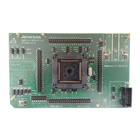
Figure 2.1 ZSSC3170 SSC Evaluation Board – Overview...............................................................................5
Figure 2.2 SSC Evaluation Board Schematic...................................................................................................7
Figure 3.1 Pin Configurations for Different Packaging Options........................................................................9
Figure 4.1 Main Window of the Evaluation Software......................................................................................12
Figure 4.2 Interface Selection Section............................................................................................................12
Figure 4.3 Additional I²CTM and LIN Interface Settings in the “Send Command” Menu..................................13
Figure 4.4 DUT Configuration Section............................................................................................................13
Figure 4.5 Bridge Sensor Adaptation and Mode.............................................................................................14
Figure 4.6 Temperature Sensor......................................................................................................................14
Figure 4.7 ADC Adjust ....................................................................................................................................14
Figure 4.8 Application and Settings ................................................................................................................15
Figure 4.9 Normal Operation Section .............................................................................................................15
Figure 4.10 Measure Output Window ...............................................................................................................16
Figure 4.11 PWM Config...................................................................................................................................17
Figure 4.12 LIN Config......................................................................................................................................18
Figure 4.13 “Sensor – Calibration” Dialog.........................................................................................................19
Figure 4.14 Displaying RAM-EEP Register Contents.......................................................................................20
Figure 4.15 “Calibration-Register (RAM)” Dialog..............................................................................................21
Figure 4.16 “Get Raw Values” Dialog ...............................................................................................................21
