ELECTRIC DUCT HEATER
RENEWAIRE.COM INSTALLATION, OPERATION AND MAINTENANCE MANUAL 1.800.627.4499
10
INSTALLATION INSTRUCTIONS
INSTALLATION
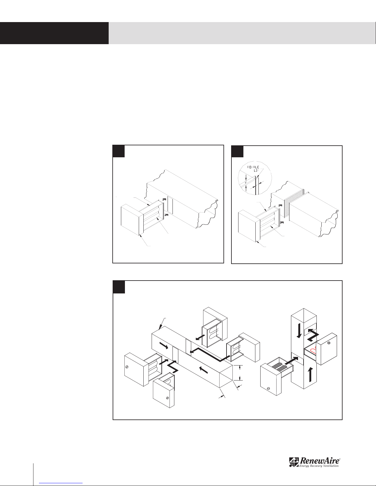
F1 Slip-In Heater F2 Flange Heater
See Figure F3 for examples of some common installation approaches (flippable EK series only).
F3 Common Installation Approaches
To install a slip-in heater Figure F1, cut an opening, as required in the side of the duct. Slide heater in
the duct using control box as template to mark the mounting screw holes. Remove unit and drill mounting
holes. Mount unit to duct with sheet metal screws. Connect high and low voltage supplies along with fan
interlock circuit (if no airflow switch is furnished). Larger heaters may require hangers.
To install a flange type heater Figure F2, insert heater between two sections of flanged duct and bolt in
place. For additional strength, the duct flange should be doubled as shown in the figure. Large heaters
may require hanger straps. Connect high and low voltage supplies along with fan interlock circuit (if no
airflow switch is furnished).
ELECTRICAL REQUIREMENTS
Refer to general wiring diagram on pages 13-14. Each heater also has its specific wiring schematic label
on the inside cover of the heater control box.
WRAPPER
SLIP-IN
CONSTRUCTION
SHOWN
AIR DUCT
BASE
HEATER
BASE HEATER
ROTATED 180
BASE
HEATER
BASE HEATER
FLIPPED 180°
* ONE HEATER- 4
POSITIONS
HORIZONTAL DUCT & AIRFLOW
with HORIZONTAL INSTALLATION
AIRFLOW
AIRFLOW
VERTICAL DUCT & AIRFLOW
AIRFLOW
AIRFLOW
* SAME HEATER- FOR
VERTICAL DUCTS
VERTICAL DUCT & AIRFLOW
* SAME HEATER -
FOR VERTICAL DUCTS
* ONE HEATER -
4 POSITIONS
HORIZONTAL DUCT & AIRFLOW
WITH HORIZONTAL INSTALLATION
S L I P - O N
CONSTRUCTION
SHOWN
AIR DUCT
B A S E
HEATER
B A S E
HEATER
BA S E HE AT E R
ROTATED 180°
BA S E HE AT E R
FLIPPED 180°
AIRFLOW
AIRFLOW
AIRFLOW
AIRFLOW
'W'
'H'
06-4141-00 REV. C E.C.O. 10438
INSTALLATION MANUAL
TUTCO DUCT HEATERS
The information and instructions in this sheet apply to Duct Heater
models for zero clearance installation in ducts.
The Duct Heaters are approved for use with heat pumps, air
conditioners, or other forced air systems. They may be controlled by
contactors, relays, sequencers or solid state devices.
The Duct Heaters are prewired, have voltage ratings to 600 volts, both
single phase and three phase.
The Duct Heaters are furnished with integral controls, except for the DD
& DHD series, which are furnished with a separate control panel for
remote mounting.
GENERAL:
Inspect heater for any possible shipping damage. Check all insulators
for breakage and inspect heater element wire for any deformation that
could cause a short circuit or ground. Make sure all fasteners are tight.
Electrical connections such as pressure terminals should be checked for
tightness.
INSTALLATION:
For safe operation and best performance, the following installation
procedures must be adhered to.
Heaters may be installed in the sides of either horizontal or vertical
ducts but never in the top or bottom of a horizontal duct. Heaters
installed in vertical ducts are tested and approved for up airflow only!
1.Install a heater a minimum of (4) feet from heat pumps or central air
conditioners.
2. At least 4 feet downstream from an air handler.
3. At least 2 feet either side of an elbow or turn.
4. At least 4 feet from any canvas duct connector or transition section for
change in duct size.
5. At least 4 feet downstream from an air filter.
6. At least 4 feet upstream from a humidifier.
Refer to the back of this sheet for: duct, electrical and air velocity
requirements.
To install a slip-in heater FIG.1, cut an opening, as required in the side
of the duct. Slide heater in the duct using control box as template to
mark the mounting screw holes. Remove unit and drill mounting holes.
Mount unit to duct with sheet metal screws. Connect high and low
voltage supplies along with fan interlock circuit (if no airflow switch is
furnished). Larger heaters may require hangers.
To install a flange type heater FIG.2, Insert heater between two sections
of flanged duct and bolt in place. For additional strength, the duct flange
should be doubled as shown in the figure. Large heaters may require
hanger straps. Connect high and low voltage supplies along with fan
interlock circuit (if no airflow switch is furnished).
500 GOULD DRIVE COOKEVILLE, TN 38506
FAX (931)432-4140 PHONE (931)432-4141
INC.
TERMINAL OR
CONTROL BOX
HEATING
ELEMENTS
FRAME
FRAME
TERMINAL OR
CONTROL BOX
HEATING
ELEMENTS