RenewAire HE4XRT User manual

HE4XRT Due to continuing product development, specications are subject to change without notice. © 2012 RenewAire LLC
134775_005 HE4XRTMan_Jan12.indd Revised 01/2012 www.renewaire.com Page 1
4510 Helgesen Drive, Madison, WI 53718
(608) 221-4499, (800) 627-4499, Fax: (608) 221-2824
[email protected] www.renewaire.com
INSTALLATION AND OPERATION MANUAL
HE4XRT
RISK OF FIRE, ELECTRIC SHOCK, OR INJURY.
OBSERVE ALL CODES AND THE FOLLOWING:
1. Before servicing or cleaning the unit, switch power
off at disconnect switch or service panel and lock-
out/tag-out to prevent power from being switched on
accidentally. More than one disconnect switch may be
required to de-energize the equipment for servicing.
2. This installation manual shows the suggested
installation method. Additional measures may be
required by local codes and standards.
3. Installation work and electrical wiring must be
done by qualied professional(s) in accordance
with all applicable codes, standards and licensing
requirements.
4. Any structural alterations necessary for installation
must comply with all applicable building, health, and
safety code requirements.
5. This unit must be grounded.
6. Danger of severe injury to bystanders and damage to
unit or property if high winds move this unit. Secure
this unit to the building!
7. Sufcient air is needed for proper combustion and
exhausting of gases through the ue (chimney) of fuel
burning equipment that might be installed in the area
affected by this equipment. If this unit is exhausting
air from a space in which chimney-vented fuel
burning equipment is located, take steps to assure
that combustion air supply is not affected. Follow the
heating equipment manufacturer’s requirements and
the combustion air supply requirements of applicable
codes and standards.
8. Use the unit only in the manner intended by the
manufacturer. If you have questions, contact the
manufacturer.
9. This unit is intended for general ventilating only. Do
not use to exhaust hazardous or explosive materials
and vapors. Do not connect this unit to range hoods,
fume hoods or collection systems for toxics.
10.When cutting or drilling into wall or ceiling, do not
damage electrical wiring and other hidden utilities.
To avoid motor bearing damage and noisy and/or
unbalanced impellers, keep drywall spray, construction
dust, etc., out of unit.
NOTE: Disconnect Switch and 24V Transformer Standard
Do not remove or disable the wiring interconnection between the
Overload Relays and the Contactors. Without this interconnection
the motor(s) will not be protected against overload.
In 2012, these ERVs may be ordered with new factory-
installed features including Isolation Dampers and Variable
Frequency Drives. Consult the supplemental Installation
and Operation Manual(s) for these features if supplied.

HE4XRT Due to continuing product development, specications are subject to change without notice. © 2012 RenewAire LLC
134775_005 HE4XRTMan_Jan12.indd Revised 01/2012 www.renewaire.com Page 2
Placement of the HE4XRT
The HE4XRT is designed for installation on a roof or other outside
location.
Select a location that is central to the inside duct runs, and close
to any other air handler that might be part of the system.
The fresh air inlet should be at least 10’ away from exhausts such
as dryer vents, chimneys, furnace and water heater exhausts, or
other sources of contamination or carbon monoxide.
Provide service access to the unit to allow for cleaning the core
and lter.
The HE4XRT is available from the factory in four different
congurations to meet different connection requirements:
Mounting the HE4XRT
On Roof Curbs:
The base of the HE4XRT Unit is designed for installation on our
optional Roof Curb. See drawing below.
Before installing HE4XRT, apply roong and counterashing to
Roof Curb as per standard practice.
Install appropriate gasket on top of Roof Curb.
Set HE4XRT in place. We recommend bolting through sides of unit
base into the Roof Curb to secure the unit against high winds.
On Equipment Rails:
Review drawing of Roof Curb and specify Equipment Rail to t.
Before installing HE4XRT, apply roong and counterashing to
Equipment Rails as per standard practice.
Set HE4XRT in place. We recommend bolting through sides of unit
base into the Equipment Rails to secure the unit against high winds.
Option Code Description of
Duct Connection Conguration Mounting Option
HE4XRTV Room Air [RA] enters bottom of unit.
Fresh Air [FA] exits bottom of unit. Roof Curb
HE4XRTR Room Air [RA] enters bottom of unit.
Fresh Air [FA] exits side of unit. Roof Curb
HE4XRTF Room Air [RA] enters side of unit.
Fresh Air [FA] exits bottom of unit. Roof Curb
HE4XRTH Room Air [RA] enters side of unit.
Fresh Air [FA] exits side of unit. Equipment Rail
OA
RA
FA
EA
HE4XRTV
(“Standard” Conguration)
RA = Room Air into Unit
OA = Outside Air into Unit
FA = Fresh Air to Inside
EA = Exhaust Air to Outside
OA
RA
EA
FA
HE4XRTR
OA
RA
FA
EA
HE4XRTF
OA
RA
EA
FA
HE4XRTH
Service Area
Service Area
48 1
4"
76 3
8"39 1
4"
117 3
4"
50 3
8"
14 3
4" 13 1
4"
34"
45
8"
25.94 54 1
8"
91"
72 5
8"
FA
RA
HE4XRT
Rigging Information
There are pairs of rigging holes at each upper corner of the
unit. Use slings or shackles at all four corners. Spreader bars are
recommended in order to avoid damage to the unit.

HE4XRT Due to continuing product development, specications are subject to change without notice. © 2012 RenewAire LLC
134775_005 HE4XRTMan_Jan12.indd Revised 01/2012 www.renewaire.com Page 3
Connecting Ducts to Unit
Any duct connections to the sides of the unit are equipped with
double-anged duct connections. These allow for connection of
ducts insulated on the inside or the outside, or for installation
of lined duct.
Connect ducts to these anges with standard S-Slips. Seal duct
exterior to the unit to keep the weather out.
Any duct connections to the bottom of the unit are made to
the duct supports on the optional roof curb. The sizes of the duct
openings in the curb allow for ducts to be insulated on the inside
or the outside.
Option Code Room Air [RA] Inlet
INNER [OUTER]
Fresh Air [FA] Outlet
INNER [OUTER]
HE4XRTV 11” x 46” (on bottom)
[13” x 48”]
12” x 32” (on bottom)
[14” x 34”]
HE4XRTR 11” x 46” (on bottom)
[13” x 48”]
12” x 32” (on side)
[14” x 34”]
HE4XRTF 12” x 40” (on side)
[14” x 42”]
12” x 32” (on bottom)
[14” x 34”]
HE4XRTH 12” x 40” (on side)
[14” x 42”]
12” x 32” (on side)
[14” x 34”]
Operation
Principal of Operation
The HE4XRT has one basic purpose: to exhaust air from a structure
and bring in fresh air from outside, while transferring heating or
cooling energy from the exhaust air to the fresh air.
The HE4XRT is a very simple device, and will accomplish this
purpose as long as the blowers for both airstreams are able to
move air through the energy-exchange core.
Checking that Unit is Operating
Air Flow
Airow should be occurring in both airstreams. Sometimes
the easiest place to conrm that air is moving is at the
weatherhoods.
If exact airow is critical, it may be desirable to permanently
install ow measuring stations and manometers in the ductwork
connected to the unit. These also can be used to determine when
lters should be cleaned or changed.
Use Static Taps in Doors to Measure Airow Rates
See “Cross-Core Static Drop” in MEASURING AIRFLOW table. These
may be used to directly measure airow in the unit.
Energy Exchange
Precise determination of installed sensible energy exchange
effectiveness requires careful measurement of temperatures
and air ows in all four air streams, and in practice is somewhat
difcult.
It is possible to conrm that energy is being exchanged simply by
feeling the ducts. If the Fresh Air duct from the unit into the room
is closer to room temperature than to the outside temperature,
energy is being recovered.
Operating Controls
A wide variety of control schemes may be selected by the
engineer, installer, or owner to meet the ventilation needs of
the facility. These may include timer clocks, occupancy sensors,
dehumidistats (for cool-weather operation), carbon dioxide
sensors, and others. DDC systems may also control the unit. Most
control schemes will operate the unit only when needed.
Continuous Operation
Continuous operation is acceptable in virtually all conditions.
Unit will not be damaged by continuous operation as long as
air ow occurs. Blower motors may overheat if lters become
completely blocked due to lack of maintenance. Motors are
thermally protected. With continuous operation, some external
frosting may occur in very cold weather (see below).
Operation in Extreme Cold Weather
Unit is capable of operating at outside temperatures down to
-10°F, with indoor humidities below 40%, without any internal
frosting. Unit can operate at more severe conditions occasionally
with little or no impact on its performance. At lower humidities,
it can operate at lower outside temperatures without freezing
the energy-exchange core.

HE4XRT Due to continuing product development, specications are subject to change without notice. © 2012 RenewAire LLC
134775_005 HE4XRTMan_Jan12.indd Revised 01/2012 www.renewaire.com Page 4
Inside Ductwork System
Follow Engineer’s Ductwork Design
Ductwork should be designed by an engineer to allow the unit to
provide the required airow.
Duct Insulation
If the inside ducts run through un-conditioned spaces, they must
be insulated, with a sealed vapor barrier on both inside and
outside of insulation.
Use Static Taps in Doors to Measure Airow Rates
See “Cross-Core Static Drop” in MEASURING AIRFLOW table. These
may be used to directly measure airow in the unit.
Change Sheaves if required to Set and Balance Air Flow
In most applications, the airow rate for both the Fresh Air and
the Exhaust Air should be roughly equal (or “balanced”) for best
performance of the HE4XRT Unit.
In most cases, the job engineer will specify ow rates and ESP
requirements. The blower motors will also be specied to provide
the required performance.
See unit specication sheet for CFM/ESP curves for available
horsepower motors.
See drawings below for examples of some common installation
approaches:
Sound Attenuation
General Practices
Take these simple steps to attenuate noise from the unit.
Outside the building:
The exhaust hood is the primary source of noise outside the
building. When practical, orient the exhaust air hood to point
away from houses or public areas.
At the Curb:
Cut the holes in the roof deck to t closely around the duct(s)
passing through the roof deck. Seal all gaps around the duct(s)
at the roof deck.
Ducts:
Make sure the ductwork at the unit outlets is stiff enough to
resist the exure and resulting booming associated with system
start-up and shut-off, as well as the turbulent ow conditions at
the blower outlets.
In general, provide smooth transitions from the ERV’s outlets to the
duct. The ducts connecting to the outlets should be straight for a
sufcient distance, with gradual transitions to the nal duct size.
These guidelines are consistent with SMACNA recommended duct
layout practices for efcient and quiet air movement. Follow
SMACNA guidelines.
Radiated Noise
The HE4XRT is insulated with high-density berglass. This provides
signicant attenuation of radiated sound from the unit itself.
The outlet ducts can be signicant sources of radiated sound
as well. The FA duct should be insulated for sound control. This
insulation should start at the unit. At a minimum the rst ten
feet of duct should be insulated. All parts of the FA and RA ducts
located in a mechanical space with noise-generating equipment
also should be insulated for sound control, both to minimize
sound radiation out of the FA duct, and also to control sound
radiation into both ducts.
Aerodynamic (Velocity) Noise
When sound attenuation is a design concern, the primary
consideration is velocity noise at the unit’s Fresh Air blower
outlet. The average velocity at the Fresh Air blower outlet is
1230 FPM when the unit is operating at 4290 CFM. The average
velocity at the Exhaust Hood outlet is 1420 FPM when the unit is
operating at 4290 CFM.
Danger of Electrical Shock when servicing an installed unit.
ALWAYS DISCONNECT POWER SOURCE BEFORE
SERVICING! More than one disconnect switch may be
required.
Proper Wiring Size Selection and Wiring Installation
are the Responsibility of the Electrical Contractor.
Electrical Specications
Electrical Options are identied on the Unit Label (located near
electrical box). Find the complete Unit Model Number in the
lower left corner of the Unit Label.
HE-4X_RTV
ROOF
Unit connected to
Return Duct of
nearby AHU.
HE-4X_RTR
Rooftop AHU
ROOF
RTR Unit with dedicated ducts
collecting Room Air.
Fresh Air is ducted into
horizontal return connection
of adjacent AHU.
HE-4X_RTV
ROOF
Stand-alone installation with
independent ducts for
exhaust and supply air.
AHU

HE4XRT Due to continuing product development, specications are subject to change without notice. © 2012 RenewAire LLC
134775_005 HE4XRTMan_Jan12.indd Revised 01/2012 www.renewaire.com Page 5
HE4XRT Conguration Chart
6 CORE: "J" = G5
11WALL TYPE: "S" = SINGLE, "D" = DOUBLE
12PHASE: "1" = SINGLE-PHASE, "3" = THREE-PHASE
21
22
OPTION 1: 24V TRANSFORMER
25 SAFETY LISTING (RESTRICTION 15)
MODEL
NUMBER
MULTIPLE-CHOICE OR
OPTIONAL FEATURES
STANDARD
FEATURES
9BASE TYPE
"V", "H", "R", "F"
10 UNUSED IN HE-4X MODELS
13VOLTAGE: (SEE RESTRICTIONS 2, 3 & 6)
7-8 INDOOR/OUTDOOR: "RT" = ROOFTOP
1-5 MODEL: "HE-4X"
20
16-17 UNUSED IN HE-4X MODELS
"1" = 115V, "4" = 460V, "5" = 208-230V, "8" = 575V
24
"L" = LISTED "N" = NON-LISTED
OPTION 4: OTHERS
"T" = TR (TRANSFORMER WITH ISOLATION RELAY)
"-" = NONE,
"W" = WHITE PAINT, "C" = CUSTOM PAINT
"X" = CUSTOM UNIT
1 2 3 4 5 6 7 8 9 10 11 12 13 14 15 16 17 18 19 20 21 22 23 24 25
DISCONNECT
"N" = NON-FUSED (STANDARD)
"F" = FUSED
OPTION 2: FILTER MONITOR
"-" = NONE,
"F" = FILTER MONITOR BOTH AIRSTREAMS
J - - - T
H E - 4 X R T
15EA HORSEPOWER14 FA HORSEPOWER
"V" = 2HP
"W"= 3HP
"X" = 5HP
RESTRICTION 6
19 UNIT CONTROL
"A" = STANDARD UNIT CONTROL WIRING
"V" = ONBOARD VFD BOTH AIRSTREAMS
"F" = ONBOARD VFD FA AIRSTREAM
"E" = ONBOARD VFD EA AIRSTREAM
DAMPERS
"-" = NO DAMPERS (STANDARD)
"D" = DAMPERS BOTH AIRSTREAMS
"E" = DAMPER EA AIRSTREAM
"F" = DAMPER FA/OA AIRSTREAM
18
23 OTHER OPTIONS (RESERVED)
"-" = NONE
RESTRICTIONS:
1: -
2: VOLTAGE CODE "1" AVAILABLE WITH PHASE CODE
"1" (SINGLE-PHASE) ONLY.
3: VOLTAGE CODES "4" & "8" AVAILABLE WITH PHASE
CODE "3" (THREE-PHASE) ONLY.
4:-
5:-
6: VOLTAGE CODES "1" AVAILABLE ONLY WITH FA/EA
HORSEPOWER CODE "V".
7: -
8:-
9:-
10:-
11:-
12: -
13:-
14: -
15: SOME UNITS WITH CUSTOM "X" CODE, HE6X &
HE8X UNITS ARE NOT SAFETY LISTED.
HE4XRT Dimensions
5 5/8" Power In
2 1/2" Control In
55 1/4" Lifting Lugs
57"
93 7/8" Overall
Pressure
Taps (4)
FRONT VIEW
(2) Ø7/8" holes
for wiring in
bottom of E-box
RTH, RTF
ONLY
FA RA
OA
RA
EA
RTV, RTR
ONLY
RTV, RTF
ONLY
RTH, RTR
ONLY
Disconnect
Switch
FA
79 3/4" Lifting Lugs
4" Top of Curb
5"
80"
20"
82" Overall
RIGHT VIEW
OA Inlet
Damper
Location
(Optional)
12" X 40"
RA Inlet
(RTH, RTF)
75 7/8" Control &
Power Wire Inlet
40 1/4"
5 1/2"
38 3/4"
12"
LEFT VIEW
E-box
EA Outlet
12" X 32"
Damper
Location
(Optional)
12" X 32"
FA Outlet
(RTH, RTR)
17 3/4" 18 5/8"
117 1/4"
Service
Area
14 3/4"
12 1/8"
40 1/8"
Curb Center
68" Service Area
28 3/4" Curb Center
82"
Unit
RA
(RTV, RTR Only)
11" X 46"
FA
(RTV, RTF Only)
12" X 32" TOP VIEW

HE4XRT Due to continuing product development, specications are subject to change without notice. © 2012 RenewAire LLC
134775_005 HE4XRTMan_Jan12.indd Revised 01/2012 www.renewaire.com Page 6
HE4XRT P1 Wiring Schematics with Independent Blower Control
24VAC
24VAC
MOTOR
(OA)
C
1
2
3
4
5
POWER SUPPLY
1 PHASE 60Hz
SEE UNIT RATING LABEL
FOR VOLTAGE, MCA
AND MOPD
Call for OA Blower Operation.
C
OPTIONS INSTALLED: INDEPENDENT BLOWER CONTROL
GND
Call for EA Blower Operation.
RELAY
RELAY
TRANSFORMER AND
CIRCUIT BREAKER
DISCONNECT
SWITCH
MOTOR STARTER
MOTOR STARTER
FUSE
(IF INSTALLED AT FACTORY)
JUMPER PROVIDED
MOTOR
(EA)
FACTORY SETTINGS:
Overload Relay Trip Settings = Motor Nameplate FLA
Overload Relay Mode Settings:"Manual" position
KEY:
"OA" = Outside Air Blower
"EA" = Exhaust Air Blower
FACTORY WIRING HIGH-VOLTAGE
FACTORY WIRING 24VAC
FIELD WIRING
1
2
3
4
5
Call for OA Blower Operation.
Call for EA Blower Operation.
OUT 24VAC
Class II
24VAC
"UNIT CONTROL USING CLASS II 24VACPOWER PROVIDED BY THIS UNIT"
24VAC POWER AVAILABLE AT TERMINALS 1 & 2
INSTALL PROVIDED JUMPER BETWEEN TERMINALS 2 & 3
"UNIT CONTROL USING CLASS II 24VAC POWER FROM ANOTHER POWER SOURCE"
24VAC POWER AVAILABLE AT TERMINALS 1 & 2
DO NOT INSTALL JUMPER BETWEEN TERMINALS 2 & 3

HE4XRT Due to continuing product development, specications are subject to change without notice. © 2012 RenewAire LLC
134775_005 HE4XRTMan_Jan12.indd Revised 01/2012 www.renewaire.com Page 7
HE4XRT P3 Wiring Schematics with Independent Blower Control
24VAC
24VAC
MOTOR
(OA)
MOTOR
(EA)
C
1
2
3
4
5
POWER SUPPLY
3 PHASE 60Hz
SEE UNIT RATING LABEL
FOR VOLTAGE, MCA
AND MOPD
Call for OA Blower Operation.
C
OPTIONS INSTALLED: INDEPENDENT BLOWER CONTROL
GND
Call for EA Blower Operation.
RELAY
1
2
3
4
5
Call for OA Blower Operation.
Call for EA Blower Operation.
OUT 24VAC
Class II
RELAY
TRANSFORMER AND
CIRCUIT BREAKER
DISCONNECT
SWITCH MOTOR STARTER
MOTOR STARTER
FUSE
(IF INSTALLED AT FACTORY)
24VAC
JUMPER PROVIDED
FACTORY SETTINGS:
Overload Relay Trip Settings = Motor Nameplate FLA
Overload Relay Mode Settings:"Manual" position
KEY:
"OA" = Outside Air Blower
"EA" = Exhaust Air Blower
FACTORY WIRING HIGH-VOLTAGE
FACTORY WIRING 24VAC
FIELD WIRING
"UNIT CONTROL USING CLASS II 24VACPOWER PROVIDED BY THIS UNIT"
24VAC POWER AVAILABLE AT TERMINALS 1 & 2
INSTALL PROVIDED JUMPER BETWEEN TERMINALS 2 & 3
"UNIT CONTROL USING CLASS II 24VAC POWER FROM ANOTHER POWER SOURCE"
24VAC POWER AVAILABLE AT TERMINALS 1 & 2
DO NOT INSTALL JUMPER BETWEEN TERMINALS 2 & 3

HE4XRT Due to continuing product development, specications are subject to change without notice. © 2012 RenewAire LLC
134775_005 HE4XRTMan_Jan12.indd Revised 01/2012 www.renewaire.com Page 8
OBSERVE THESE LIMITS TO WIRE LENGTH AND GAUGE,
in order to ensure reliable operation of the control system.
Wire Gauge #22 #20 #18 #16 #14 #12
Circuit Length 100’ 150’ 250’ 400’ 700’ 1000’
“Circuit Length” is distance from ERV to Control Device.
How to Reset the 24VAC Circuit Breaker
If the transformer is subjected to an excessive load or a short
circuit, the circuit breaker will trip to prevent the failure of the
transformer. When it trips the circuit breaker’s button pops up.
Shut off the primary-side power to the unit, and remove the
excessive load or the short. The circuit breaker can be reset
about fteen seconds after it trips by pressing in the button.
NOTE: INSTALLING CONTRACTOR:
If primary-side voltage is 230VAC, move black primary-side lead
from transformer’s “208V” terminal to the transformer’s terminal
marked “240V” (“230V” in some units).
Do not move the black primary-side lead that is connected to the
transformer’s “COM” terminal.
Limits of Power Output
If limits on wire gauge and length are observed, you may connect
control devices that draw up to 8VA to the blue and red wires.
More than one device can be connected as long as total steady-
state load does not exceed 8VA.
This ERV is provided with a Class II 24VAC power supply system that
operates the unit’s contactor(s) for EV450 and HE1X. The ERV’s
24VAC Power Supply can also be used to power the externally-
installed controls system: up to 8VA of power is available.
The unit’s power supply system includes isolation relay(s) so you
can use external controls whose contact ratings are as low as 50mA
(1.2VA). Also, it is possible to operate the isolation relays with 24VAC
power from an external source (with proper wiring connections).
Abuilt-in circuit-breaker prevents damage to the transformer and other
low-voltage components in the event of a short-circuit or overload. In
extreme cases, the transformer itself is designed to fail safely.
24VAC Power Supply
Provided with this ERV Unit
1. Connect only to components intended for use with 24VAC
power.
2. Do not undersize the low-voltage wires connected to this
device. Observe the wire length and gauge limits indicated
in this manual.
3. Do not overload this unit’s 24VAC power supply system.
Conrm that the power requirements of devices you connect
to this power supply system do not exceed 8VA in total.
4. If an external source of 24VAC power is used to control the
unit, consult the wiring schematics and connect the external
power only to the specied terminals in order to avoid
damaging the unit or external controls. Connect only CLASS
II power to the control terminals of this unit.
5. Unit is not equipped to receive analog signals (such as
1-10vdc or 4-20mA).
6. Unit is not equipped to communicate directly with Building
Management Systems (such as BACNET, LONWORKS, etc.).
However, the unit can be controlled by powered or non-
powered contacts operated by any kind of control system.
Specications
• Nominal Output Voltage under load: 24VAC
• Typical Output Voltage at no load: 29-31V
• Minimum contact rating
for connected control device: (50mA (1.2VA)
• Circuit Breaker Trip Point: 3A
Motor Starters
This unit uses IEC-style motor starters to protect the motors
against overload.
IEC-style motor starters use Overload Relays to detect excessive
current and interrupt the control circuit that engages the motor’s
contactors.
Overload Relays are sized to Full Load Amp (FLA) rating of the
protected motor. The Overload Relays can be adjusted to trip
(interrupt the control circuit) at a specic setting within a range.
Overload Relays should initially be set at the FLA rating of the
motor (see Unit Rating Label). If necessary to prevent nuisance
tripping at start-up, the Relays can be adjusted to trip no higher
than 115% of the motor’s FLA rating.
For safest operation, the overload relays should also be used in
manual reset mode with trip test capability.
NOTE: As factory-wired, if one blower motor is shut down due to
overload by its Motor Starter, the other motor will also be shut down.
NOTE: Terminals 96 & 97 of the Overload Relays and terminals 14
& 13 of the Contactors are normally-open dry contacts that may
be used to signal that the contactors are closed and/or that the
Overload Relays have tripped.
DANGER OF INJURY OR DAMAGE.
The motors in this unit must not be run at an amperage
that exceeds the motor’s rated full load amps and
overload relays on the motor starters must be set at
or below motor full load amps. For safest operation,
the overload relays should also be used in hand reset
mode with trip test capability.
It is the installer’s responsibility to measure the
operating amperage of each motor. If the full load amp
rating is exceeded, the amp draw must be reduced by
substituting a smaller motor pulley or by adjusting
the variable sheave. Continue these adjustments
until the actual amperage is no more than the motor’s
faceplate full load amps.
Failure to make this adjustment may result in
unsafe motor winding temperatures or tripping of
the supplied motor starter’s overload relay motor
protection devices set at full load amps.
DANGER OF INJURY OR DAMAGE.
The relay must be set for correct FLA rating depending
on the motor horsepower. See Unit Rating Label on
motor for HP and FLA specications.
Adhere to applicable local codes when adjusting the
dial setting of the overload relays.
The Overload Relay output contacts 95 & 96 must
remain in series with the low-voltage control circuit!
Altering this will create a hazardous situation in
which the motor is not protected against overload!

HE4XRT Due to continuing product development, specications are subject to change without notice. © 2012 RenewAire LLC
134775_005 HE4XRTMan_Jan12.indd Revised 01/2012 www.renewaire.com Page 9
E. Control System with 2 Non-powered Relay Contacts: Use
this schematic if the external control system provides no
voltage or current at its output contacts. Install jumper
(provided) between terminals 2 & 3. Connect one side of
each of the output contacts to Terminal 1. Connect the
other side of the output contact to control the FA Blower
to Terminal 4, and the output contacts to control the EA
Blower to Terminal 5.
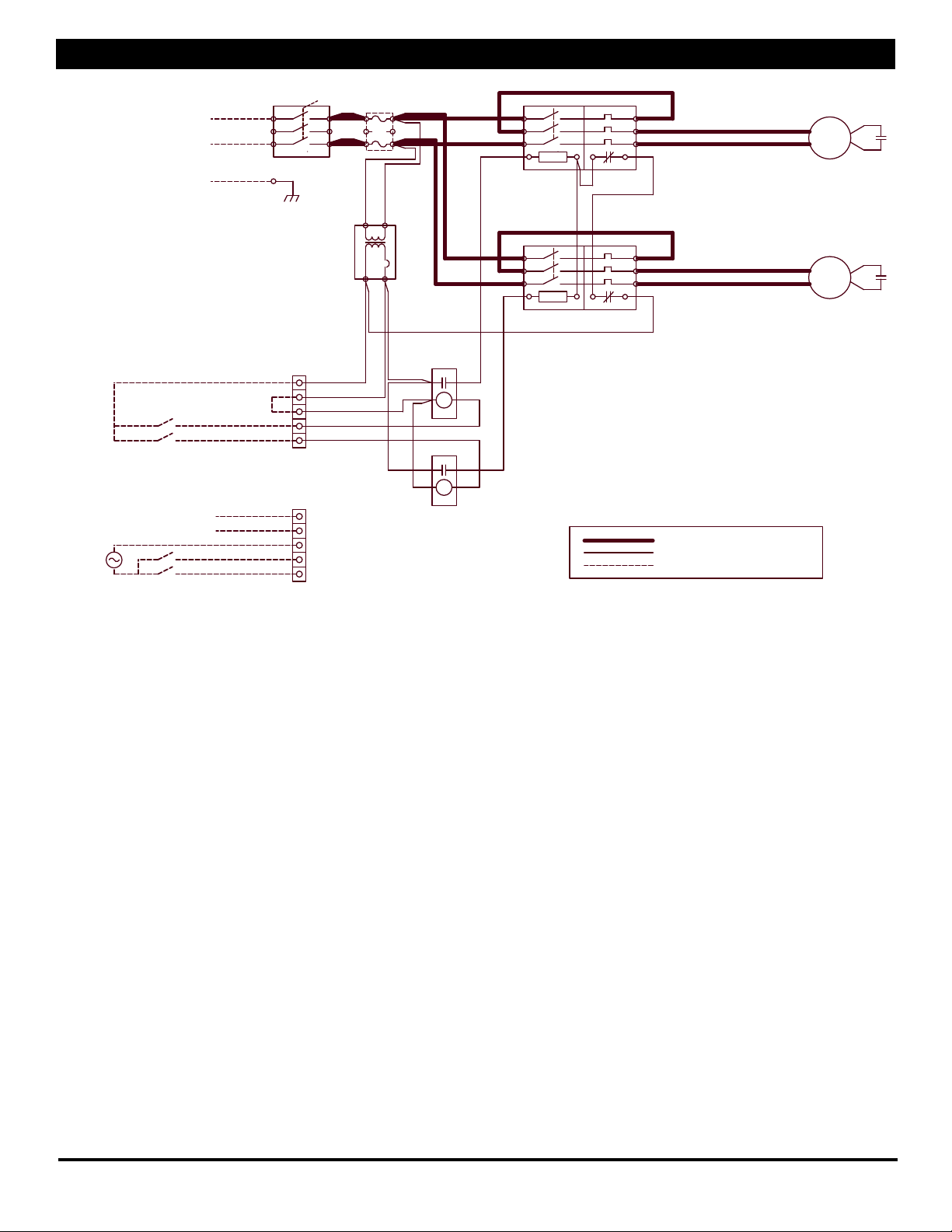
Control Wiring Schematics
NOTE: The simplied schematics below show only the relevant
portions of the low-voltage control circuit in the ERV unit and
representational external control approaches. See the
complete unit schematics elsewhere in this manual.
C. Control Sending 24VAC “On” Signal (from an external
power source) to ERV: Make sure jumper is NOT installed
between Terminals 2 & 3. Now you safely can apply 24VAC
to the Terminals 3 & 4 to operate the ERV’s Isolation Relay
for OA/FA Blower. Install jumper (provided) between
terminals 4 & 5 to operate the ERV’s Isolation Relay for
the RA/EA Blower.
D. Control operating on Unit’s 24VAC Power Supply: 24VAC
power is available at the Terminals 1 & 2. CAUTION:
external control system should not draw more than 8VA.
Install jumper (provided) between terminals 2 & 3.
Connect the switched output of the Control to Terminal
4 to operate the ERV’s Isolation Relay for OA/FA Blower.
Install jumper (provided) between terminals 4 & 5 to
operate the ERV’s Isolation Relay for the RA/EA Blower.
F. Control System Sending two 24VAC “On” Signals from
an external power source: Make sure the jumper is NOT
installed between Terminals 2 & 3. Now you safely can
apply one of the 24VAC signals to Terminals 3 & 4 to operate
the ERV’s isolation relay for the Fresh Air Blower. Apply
the second 24VAC signal to Terminals 3 & 5 to operate the
ERV’s isolation relay for the Exhaust Blower (make sure the
polarity of each wire connected to Terminal 3 is the same).
Make sure the control provides no voltage or current at its
output terminals.
Supply only 24VAC (not VDC) from a Class II Power Source.
A. Single 2-wire Control, unpowered: Use schematic below
if the control requires no power from the unit to operate
and acts like a simple on/off switch. The control must not
supply any power to the ERV unit. Install jumper (provided)
between terminals 2 & 3. Connect the control’s contacts to
terminals 1 & 4 to operate the ERV’s Isolation Relay for OA/
FA Blower. Install jumper (provided) between terminals 4 &
5 to operate the ERV’s Isolation Relay for the RA/EA Blower.
Supply only 24VAC (not VDC) from a Class II Power Source.
G. Control System Operating Isolation Dampers with End
Switches: Use Isolation Dampers with electrically separate
end switches. The end switches are used to separately
control the ERV unit’s Isolation Relays. This ensures that
each damper is open before the respective blower starts up.
NOTE: Because the ERV’s Motor Starters will only be
operating once the Dampers are open, the power draw
of the Damper Actuators is allowed to be as much as 35VA
while opening (including power draw of the external
control system, if any). However, the power draw of the
fully-opened (stalled) Actuators (and external control
system if any) must be less than 8VA. (Most damper
actuators have much lower power draws.)
B. Single 2-wire Control on separate Power Supply, no power
present at Control Output: Wire as shown for the Single
2-wire control (A. above).
MPU
Connect Terminals 2 & 3
Connect Switch between Terminals 1 & 4
UNIT INTERNAL CONTROL WIRING
(SIMPLIFIED)
A SWITCH OR NON-POWERED
CONTROL USING UNIT'S 24VAC POWER
SUPPLY
UNIT INTERNAL CONTROL WIRING
(SIMPLIFIED)
24VAC FROM AN EXTERNAL SOURCE
Unit's 24VAC
Power Supply
UNIT INTERNAL CONTROL WIRING
(SIMPLIFIED)
AN EXTERNAL CONTROL USING UNIT'S
24VAC POWER SUPPLY
24VAC Available at Terminals 1 & 2
Unit's 24VAC
Power Supply
Unit's 24VAC
Power Supply
Connect Terminals 2 & 3
UNIT INTERNAL CONTROL WIRING
CIsolation Relay Coil (Fresh Air)
(SIMPLIFIED)
A SWITCH OR NON-POWERED
CONTROL USING UNIT'S 24VAC POWER
SUPPLY Unit's 24VAC
Power Supply
CIsolation Relay Coil (Exhaust Air)
UNIT INTERNAL CONTROL WIRING
CIsolation Relay Coil (Fresh Air)
(SIMPLIFIED)
TWO EXTERNAL RELAY CONTACTS
SUPPLYING 24VAC FROM AN
EXTERNAL SOURCE Unit's 24VAC
Power Supply
CIsolation Relay Coil (Exhaust Air)
CIsolation Relay Coil (Fresh Air)
CIsolation Relay Coil (Exhaust Air)
CIsolation Relay Coil (Fresh Air)
CIsolation Relay Coil (Exhaust Air)
CIsolation Relay Coil (Fresh Air)
CIsolation Relay Coil (Exhaust Air)
Connect Terminals 4 & 5
Connect Switch between Terminals 1 & 4
Connect Terminals 4 & 5
Connect Terminals 2 & 3
1
2
3
4
5
1
2
3
4
5
1
2
3
4
5
1
2
3
4
5
1
2
3
4
5

HE4XRT Due to continuing product development, specications are subject to change without notice. © 2012 RenewAire LLC
134775_005 HE4XRTMan_Jan12.indd Revised 01/2012 www.renewaire.com Page 10
HE4XRT Airow Performance
Motor
HP
Blower
RPM
Turns
Open
External Static Pressure (in. w.g.)
0.00 0.25 0.50 0.75 1.00 1.25 1.50
SCFM BHP SCFM BHP SCFM BHP SCFM BHP SCFM BHP SCFM BHP SCFM BHP
2
1186 4 3099 1.5 2790 1.3 2295 1.1 1790 0.8 1150 0.6
1326 2 3465 2.2 3185 1.9 2810 1.7 2335 1.4 1885 1.2 1290 0.9
1466 0 2451 1.8 2026 1.5 1485 1.2
3 (a)
1455 4 3812 2.7 3550 2.5 3285 2.3 2820 2.0 2400 1.7 1970 1.5 1450 1.2
1527 3 3750 2.9 3500 2.7 3085 2.4 2676 2.1 2300 1.9 1815 1.5
1598 2 3350 2.6 2950 2.6 2590 2.3 2175 2.0
1670 1 3210 3.0 2870 2.7 2500 2.4
1742 0 2800 2.9
5 (b)
1623 4 4165 3.7 3965 3.5 3750 3.3 3475 3.0 3055 2.5 2685 2.3 2290 2.0
1728 2 4240 4.3 4050 4.0 3820 3.7 3450 3.3 3050 3.0 2720 2.6
1832 0 4345 4.9 4140 4.5 3850 4.2 3490 3.7 3145 3.3
(a) Sheaves for 3HP motors can be adjusted from 1742 RPMs at 0 turns to 1419 RPM at 4.5 turns. Operating range shown is best for motor efciency.
(b) Sheaves for 5HP motors can be adjusted from 1832 RPMs at 0 turns to 1493 RPM at 6.5 turns. Operating range shown is best for motor efciency.
HE4XRT Replacement Parts
M
N
P
L
R
S
ACORES
BFILTERS
CBLOWER DOOR
DTURN LATCH
EDISCONNECT SWITCH
FTRANSFORMER
GISOLATION RELAY
HOVERLOAD RELAY
JCONTACTOR
K CORE DOOR
LMOTOR
MMOTOR MOUNT
NBLOWER
PMOTOR SHEAVE
RBELT
S BLOWER SHEAVE
T INTAKE HOOD
UEXHAUST HOOD
A
B
C
G
D
H
E
J
F
K
T
U

HE4XRT Due to continuing product development, specications are subject to change without notice. © 2012 RenewAire LLC
134775_005 HE4XRTMan_Jan12.indd Revised 01/2012 www.renewaire.com Page 11
Measuring Airow
Equipment Required
• A magnehelic gauge or other device capable of measuring 0
to 1.5 in. water of differential pressure.
• 2 pieces of natural rubber latex tubing, 1/8” ID, 1/16” Wall
works the best. NOTE: Be sure to remove cap from pressure
port before inserting tubing. Insure tubing is well seated
in pressure ports. NOTE: The tubing should extend in the
pressure port approx. 1 inch.
Cross Core Static Pressure Measurement Instructions
• The individual differential static pressures (DSP) can be
measured using the installed pressure ports located in the
front of the units core access doors. NOTE: These ports
have been carefully located on the unit as to give you the
most accurate airow measurement. NOTE: Do not relocate
pressure ports.
• To read SCFM of Fresh Air (FA) install the “high” pressure side
(+) of your measuring device to the Outside Air (OA) port and
the “low” pressure side (-) to the Fresh Air (FA) port.
• To read SCFM of Room Air (RA) install the “high” pressure
side (+) of your measuring device to the Room Air (RA) port
and the “low” pressure side (-) to the Exhaust Air (EA) port.
• Use the reading displayed on your measurement device to
cross reference the CFM output using the conversion chart.
NOTE: Be sure to replace cap into pressure port when air
ow measuring is completed.
ONLY
RTH, RTF
RA
OA
FA
RTV, RTF
ONLY
RTV, RTR
ONLY
RA
RTH, RTR
FA ONLY
FRONT
VIEW
E-box
Pressure Taps (4)
EA
Differential Static Across Core DSP vs. CFM
HE4XRT
DSP 0.20 0.30 0.40 0.50 0.60 0.70 0.80 0.90 1.00
Fresh Air (FA) CFM 1450 2030 2600 3180 3760 4340 4910 5490 6070
Room Air (RA) CFM 840 1370 1900 2430 2960 3480 4020 4550 5080
The proper operating airow range for this model is 1000 -
4400 CFM.

HE4XRT Due to continuing product development, specications are subject to change without notice. © 2012 RenewAire LLC
134775_005 HE4XRTMan_Jan12.indd Revised 01/2012 www.renewaire.com Page 12
Maintenance
SUMMARY MAINTENANCE REQUIREMENTS
Change Filters
Inspect Blower
Tension Blower Belt
General Cleaning and Inspection
Clean Energy Exchange Cores
CHANGING THE FILTERS
Inspect and/or replace lters every two or three months when
the unit is in regular use, or as needed.
• Turn off unit completely! Lock-out and tag-out the unit
disconnect switch.
• Open the Door. The door is secured with turn-type latches,
plus one Phillips-head securing screw. Keep the securing screw.
NOTE: Always replace securing screw when reinstalling door.
• Remove and dispose of all (8) lters. Replace all (8) lters.
NOTE: See chart for information on the initial resistance of the
lters originally supplied with this unit. If replacement lters
have higher resistance, the airow of the system will be lower.
• Close door; reinstall securing screw.
Blower Inspection
Inspect Blowers every time you change the lters.
• Conrm bearings are still secure to blower shaft. It should
not be possible to move the blower shaft back and forth
along its length.
• Conrm blower wheel is not rubbing against the blower inlet
or housing.
Blower Belt Tension
Check belt tension every time you change the lters.
• Inspect belt(s) for cracking or uneven wear.
• Check that sheaves are properly aligned so that belt runs straight.
Properly tensioned belt will deect 0.25” when pressed at the
center point with the following force:
2 HP BLOWER - 3 pounds
3 HP BLOWER - 4 pounds
5 HP BLOWER - 5 pounds
GENERAL CLEANING AND INSPECTION
Perform general cleaning and inspection when changing lters.
• Remove dust from blower wheels periodically.
• Remove paper, leaves, etc. from inlet and outlet screens.
• Inspect for insect nests.
TO CLEAN THE ENERGY EXCHANGE CORE
Clean the core annually.
• Remove the lters.
• Vacuum the exposed faces of the energy exchange core with
a soft brush.
• Vacuum out dust from the rest of the unit case.
• Install new lters.
Initial Resistance of Filters supplied with this unit:
INITIAL PRESSURE DROP: 20" x 20" & 16" X 25" MERV 8 FILTERS
RENEWAIRE PART NUMBERS 103054 & 103057
0
0.1
0.2
400 500 600 700 800 900 1000
CFM/FILTER
PRESSURE DROP THROUGH FILTER ("H2O)
"20X20_&_16X25_MERV8_JUNE06.pdf" 6/26/06
Certified data provided by filter manufacturer.
INITIAL PRESSURE DROP 20” x 20” MERV 8 FILTERS
RENEWAIRE SERVICE PART NUMBER 990083
Filter Specications:
(8) 20” x 20” x 2”(nominal) pleated lters
Actual size: 19.5” x 19.5” x 1.75”
Unit shipped with MERV-8 Filters
Minimum recommended effectiveness: MERV-6
Danger of injury from un-guarded drive belts in unit.
Disconnect power to unit before opening door.
Danger of injury if unit starts unexpectedly. Switch
power off at service disconnect. Lock-out/tag-out the
disconnect.
Filters must be used or the energy exchange core will
become blocked by dust and the unit will not do its job.
In extreme cases components may be damaged.
Incorrect Belt Tension will damage this blower!
DO NOT WASH THE ENERGY EXCHANGE CORE.
Keep it away from water or re to avoid damaging it.
Always handle the core carefully.
Lubrication
If the motors used in this ERV are equipped with grease ttings,
motors must be lubricated as part of routine maintenance. Use
Exxon Polyrex or equivalent at 2500 operating hour intervals.
Table of contents
Other RenewAire Test Equipment manuals