Renfert TOP spin User manual

Bedienungsanleitung
Instruction manual • Mode d´emploi
Istruzioni d’uso • Instrucciones para el servicio
Инструкция по эксплуатации
操作说明书 • 取扱説明書 • 사용 설명서
Made in Germany
Top spin
No. 1835
21-9728 14072014 / D
Ideas for dental technology

Seriennummer, Herstelldatum und Geräte-Version befinden sich auf dem Geräte-Typenschild.
Serial number and date of manufacturing are shown on the type plate of the unit.
Le numéro de série et la date de fabrication se trouvent sur la plaque signalétique de l‘appareil.
Il numero di serie e la data costruzione si trovano sulla targhetta dell‘apparecchio.
El número de serie y la fecha de fabricación están indicados en la placa identificadora del aparato.
Номер серии и дата изготовления указаны на фирменной табличке прибора.
产品编号和生产日期被标于本机的铭牌上。
シリアル番号、製造日および装置のバージョンは装置の型番号ラベルに記載されています。
시리얼넘버, 제조일자 및 기기 버전은 기기의 명판에 표시되어 있습니다.

1
3
2
4
65

10
12
11
7
9
8

13
15
14
16
17 18

19
a)
b)
20
21 22
23

DE- 1 -
Top spin
Nr. 1835
Bei bestimmungswidriger An-
wendung ist der vorgesehene
Schutz nicht mehr gewährleistet
und es besteht Verletzungsge-
fahr.
2.3 Umgebungsbedingungen
(nach DIN EN 61010-1)
Das Gerät darf nur betrieben werden:
•in Innenräumen,
•bis zu einer Höhe von 2.000 m über
Meereshöhe,
•bei einer Umgebungstemperatur von
5 - 40ºC [41 - 104ºF] *),
•bei einer maximalen relativen Feuchte
von 80% bei 31ºC [87,8ºF], linear abneh-
mend bis zu 50% relativer Feuchte bei
40ºC [104ºF] *),
•bei Netz-Stromversorgung, wenn die
Spannungsschwankungen nicht größer
als 10% vom Nennwert sind,
•bei Überspannungskategorie II.
•bei Verschmutzungsgrad 2.
*) Von 5 - 30ºC [41 - 86ºF] ist das Gerät bei einer
Luftfeuchtigkeit von bis zu 80% einsatzfähig. Bei
Temperaturen von 31 - 40ºC [87,8 - 104ºF] muss
die Luftfeuchtigkeit proportional abnehmen, um die
Einsatzbereitschaft zu gewährleisten (z.B. bei 35ºC
[95ºF] = 65% Luftfeuchtigkeit, bei 40ºC [104ºF] = 50%
Luftfeuchtigkeit). Bei Temperaturen über 40ºC [104ºF] darf
das Gerät nicht betrieben werden.
3. Gefahrenhinweise
3.1 Verwendete Symbole
In dieser Anleitung und an dem Gerät
ndenSiefolgendeZeichen:
Gefahr
Es besteht unmittelbare Verlet-
zungsgefahr.
Elektrische Spannung
Es besteht Gefahr durch elek-
trische Spannung.
DEUTSCH Originalbetriebsanleitung
1. Einleitung
Es freut uns, dass Sie sich zum Kauf des
Top spin- Pinbohrgeräts entschieden ha-
ben, das einen neuen Standard bezüglich
Funktion, Leistungsfähigkeit, Sicherheit
und Formgebung setzt.
Bitte beachten Sie folgende Hin-
weise um eine lange und
problemlose Funktion zu
gewährleisten.
2. Beschreibung /
Anwendungsbereich
2.1 Bestimmungsgemäße
Anwendung
Das Top spin ist ein Gerät zum Bohren
von positionsgenauen Befestigungsboh-
rungenfürPinsinZahnmodellenaus
Gips oder Epoxidharz für unterschiedliche
Pin-Systeme.
Sein Einsatz erfolgt ausschließlich in
zahntechnischen Betrieben.
2.2 Bestimmungswidriger
Gebrauch
Das Produkt darf nicht dazu verwendet
werden um in Metallen zu bohren.
Das Produkt darf nicht zum Fräsen ver-
wendet werden. Bei Bruch des Bohrers
besteht Verletzungsgefahr.
An diesem Produkt dürfen nur die von
der Firma Renfert GmbH gelieferten oder
freigegebenenZubehör-undErsatzteile
verwendet werden. Die Verwendung von
anderenZubehör-oderErsatzteilenkann
die Sicherheit des Gerätes beeinträch-
tigen, birgt das Risiko schwerer Verlet-
zungen, kann zu Schäden an der Umwelt
oder zur Beschädigung des Produkts
führen.

DE - 2 -
Achtung
Bei nicht Beachtung des Hin-
weises besteht die Gefahr der
Beschädigung des Geräts.
Hinweis
Gibt einen für die Bedienung
nützlichen, die Handhabung
erleichternden Hinweis.
Laser
Nicht in den Laserstrahl blicken.
Nur zur Verwendung in Innenräu-
men.
Bedienungsanleitung beachten.
3.2 Gefahrenhinweise
•Bei dem Top spin handelt es sich
um ein elektrisches Gerät mit Gefah-
renpotential. Dieses Gerät darf nur
von autorisierten Fachkräften nach
Überprüfung der Konformität be-
züglichlandesspezischenNormen
angeschlossen / benutzt werden.
•Beachten Sie die Unfallverhütungs-
vorschriften der Berufsgenossen-
schaft und folgende Sicherheitshin-
weise für das Bohren.
•Vor Inbetriebnahme Spannungsanga-
be des Geräts mit der Netzspannung
vergleichen.
•Geräte mit schadhaften Zuleitungen
oder anderen Defekten dürfen nicht
mehr betrieben werden.
•Vor Rüstarbeiten am Gerät Netzste-
cker ziehen.
•Bei angeschlossener Spannungsver-
sorgung nie an den Bohrer fassen.
Bei unvermitteltem Anlauf des Bohr-
gerätes besteht Verletzungsgefahr!
•Nicht mit offenen langen Haaren oder
losen bzw. weiten Bekleidungsteilen
am Top spin arbeiten. Durch Einzie-
hen und Aufwickeln besteht Verlet-
zungsgefahr.
•Gerät ist nur zum Bohren von Gips-
und Epoxydharzmodellen konstruiert.
•Nicht an den drehenden Bohrer
fassen.
•BedienungdesGerätsnurmitauie-
gendem Modell.
•Modell beim Bohren nicht unmittelbar
über dem projizierten Laserpunkt
festhalten – Verletzungsgefahr.
Achtung!
Laserstrahlung!
Laser Klasse 2
Nicht in den Strahl blicken!
•Es liegt in der Verantwortung des
Betreibers, dass nationale Vorschrif-
ten bei Betrieb und bezüglich einer
wiederholten Sicherheitsprüfung von
elektrischen Geräten eingehalten
werden. In Deutschland sind dies die
BGV A3 in Zusammenhang mit VDE
0701-0702.
3.3 Haftungsausschluss
Renfert GmbH lehnt jegliche Schadenser-
satz- und Gewährleistungsansprüche ab
wenn:
•das Produkt für andere, als den in
der Bedienungsanleitung genannten,
Zwecke eingesetzt wird;
•das Produkt in irgendeiner Art und
Weise verändert wird - außer den in
der Bedienungsanleitung beschrie-
benen Veränderungen;
•das Produkt von nicht autorisierten
Stellen repariert oder nicht mit Ori-
ginal Renfert Ersatzteilen eingesetzt
wird;
•das Produkt trotz erkennbarer Sicher-
heitsmängel weiter verwendet wird.
4. Montage / Inbetriebnahme
Stellen Sie das Top spin auf eine ebene
Unterlage.
ZweiAnwendungspositionensindmöglich:
1. Arbeiten im Stehen = 0°-Stellung
(Bild 1).
2. Positionswechsel: 180°-Drehung des
Gehäusefußes (Bild 2).
3. Arbeiten im Sitzen = 16°-Stellung
(Bild 3).

DE- 3 -
Prüfen Sie, ob die Netzspannung
mit der aufgedruckten Spannung
auf dem Geräte-Typenschild
übereinstimmt.
4. Verbindung Netzstecker – Top spin
(Bild 4).
5. Verbindung Netzstecker – Steckdose
(Bild 5).
6. Netzschalter auf I (Bild 6).
7. Bohrtiefeneinstellung überprüfen. Pro-
bebohrung durchführen. Die Bohrtiefe
lässt sich stufenlos justieren (Bild 7).
Das Top spin ist jetzt betriebsbereit.
5. Bedienung / Bohren
1. LaserstrahlaufZahnstumpfausrichten
(Bild 8).
2. ZahnkranzmitbeidenHändenfesthal-
ten (Bild 8).
3. Automatischer Motorstart durch Absen-
ken des Modelltisches (Bild 9).
4. Für stärkeren Anpressdruck den
Gegenhalter am Top spin benutzen
(Bild 10).
5. Top spin ausschalten (Bild 11).
Achtung
Bohren Sie kein Metall mit dem
Top spin!
Zum Bohren keine Schmier- oder
Schneidmittel verwenden!
5.1 Wechsel des Bohrers
1. Top spin ausschalten (Bild 11), Netz-
stecker ziehen.
2. Modelltisch anheben (Bild 12), rastet in
Endposition automatisch ein.
3. Staubschale entnehmen (Bild 13).
4. Nut der Bohrspindel auf Arretierstift
ausrichten (Bild 14).
5. Arretierstift in Nut der Bohrspindel
drücken (Bild 15) und halten.
6. Schnellspannvorrichtung durch Drehen
im Gegenuhrzeigersinn lösen (Bild 16).
7. Bohrer entnehmen (Bild 17) und neuen
Bohrer einsetzen.
8. Schnellspannvorrichtung durch Drehen
im Uhrzeigersinn handfest anziehen
(Bild 18).
9. Staubschale einlegen (Bild 13).
10. Modelltisch absenken (Bild 19).
Achtung
Nur Original Renfert Bohrer
verwenden!
5.2 Wechsel der Netzsicherung
1. Top spin ausschalten (Bild 11), Netz-
stecker ziehen.
2. Rasterung oben und unten lösen
(Bild 22a).
3. Halter mit Sicherungen herausziehen
(Bild 22a).
4. Defekte Sicherungen auswechseln
(Bild 23),
Sicherungstyp: siehe „technische
Daten“.
5. Halter mit den Sicherungen zurückset-
zen (Bild 22b).
6. Reinigung / Wartung
Das Top spin nur trocken reinigen.
1. Top spin ausschalten (Bild 11).
2. Modelltisch anheben (Bild 12), rastet in
Endposition automatisch ein.
3. Staubschale entnehmen (Bild 13).
4. Staubschale entleeren und zurück-
setzen.
5. Modelltisch absenken (Bild 19).
6.1 Reinigung der Schnell-
spannvorrichtung
1. Bohrer entnehmen
(siehe 5.1, Pkt. 1 - 7).
2. Spannmutter durch Drehen im Gegen-
uhrzeigersinn demontieren (Bild 20).
3. Spannzange entnehmen und zusam-
men mit der Spannmutter reinigen
(Bild 21).
4. Spannzange einsetzen, Spannmutter
aufsetzen und durch Drehen im Uhr-
zeigersinn montieren.
5. Bohrer einsetzen
(siehe 5.1, Pkt. 8 - 10)

DE - 4 -
7. Ersatzteile
Entnehmen Sie die Verschleiß- bzw.
Ersatzteilnummern bitte der Ersatzteilliste
am Ende dieser Anleitung.
8. Garantie
Bei sachgemäßer Anwendung gewährt
Renfert auf alle Teile des Top spin eine
Garantie von 3 Jahren.
Voraussetzung für die Inanspruchnahme
der Garantie ist das Vorhandensein der
Original-Verkaufsrechnung des Fachhan-
dels. Ausgeschlossen aus der Garantielei-
stung sind Teile, die einer natürlichen Ab-
nutzung ausgesetzt sind (Verschleißteile),
sowie Verbrauchsteile. Diese Teile sind in
der Ersatzteilliste gekennzeichnet.
Die Garantie erlischt bei unsachgemäßer
Verwendung, bei Missachtung der Bedie-
nungs-, Reinigungs-, Wartungs- und An-
schlussvorschriften, bei unsachgemäßer
Eigenreparatur oder Reparatur durch
nicht autorisiertes Personal, bei Verwen-
dung von Ersatzteilen anderer Hersteller
und bei ungewöhnlichen oder nach den
Verwendungsvorschriften nicht zulässigen
Einüssen.
Garantieleistungen bewirken keine Verlän-
gerung der Garantie.
9. Entsorgungshinweis für
die Länder der EU
ZurErhaltungundSchutzderUmwelt,der
Verhinderung der Umweltverschmutzung,
und um die Wiederverwertung von Roh-
stoffen (Recycling) zu verbessern, wurde
von der europäischen Kommission eine
Richtlinie erlassen, nach der elektrische
und elektronische Geräte vom Hersteller
zurückgenommen werden, um sie einer
geordneten Entsorgung oder einer Wie-
derverwertung zuzuführen.
Die Geräte, die mit diesem Symbol
gekennzeichnet sind, dürfen innerhalb
der Europäischen Union daher nicht über
den unsortierten Siedlungsabfall entsorgt
werden:
Bitte informieren Sie sich bei Ihren lokalen
Behörden über die ordnungsgemäße
Entsorgung.
9.1 Besondere Hinweise für
Kunden in Deutschland
Bei den Renfert Elektrogeräten handelt
es sich um Geräte für den kommerziellen
Einsatz.
Diese Geräte dürfen nicht an den kom-
munalen Sammelstellen für Elektrogeräte
abgegeben werden, sondern werden von
Renfert zurückgenommen.
HinweisedazundenSieauchimInternet
unter
www.renfert.com
10. Technische Daten
Spannung: 230 V, 50 Hz
115 V, 60 Hz
Aufnahmeleistung: 150 W
Sicherung:
1835-0000 (230V/50Hz): M1A (1A,
mittelträge)
1835-4000 (115V/60Hz): M2A (2A,
mittelträge)
Drehzahl: 16000 1/min.
Maße (BxHxT): 166 x 322 x 149 mm
[6,54 x 12,69 x 5,87 inch]
Gewicht: 5 kg
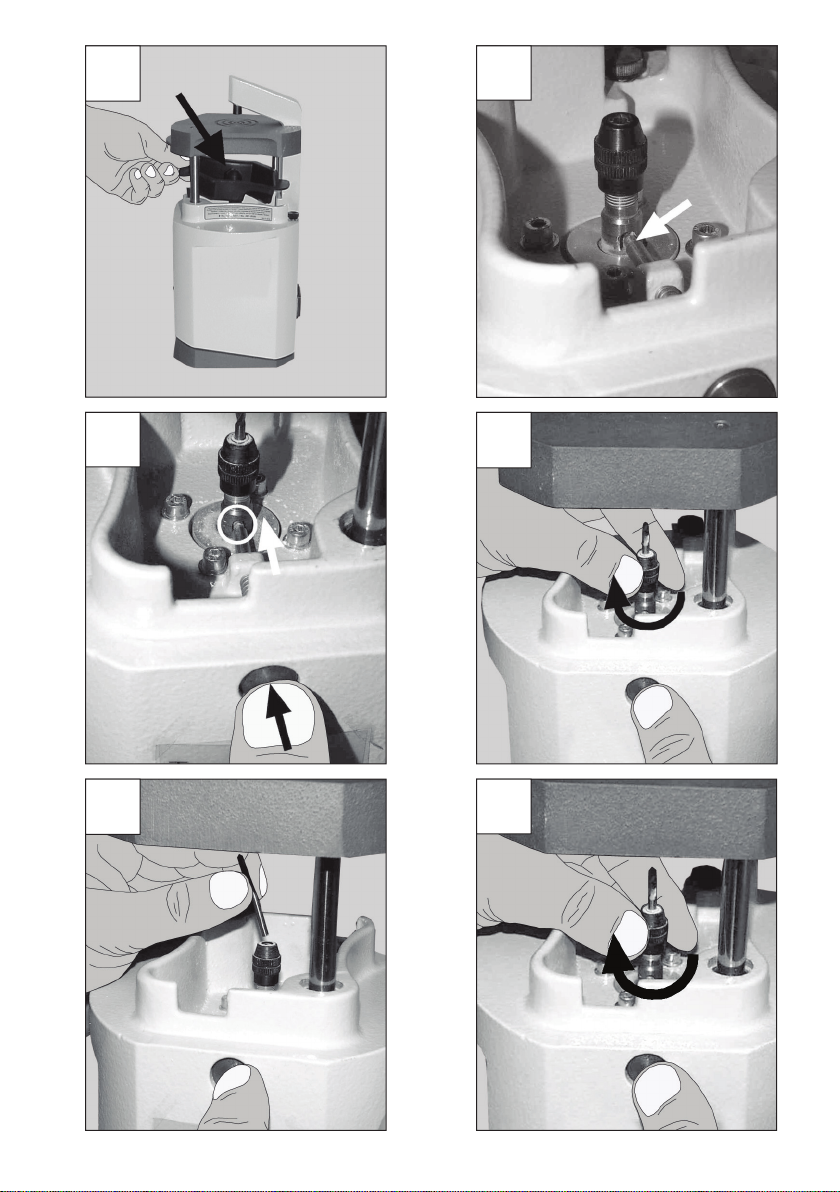
Bohrertyp: HM-Bohrer mit Schaft-Ø 3 mm
[0,12 inch]
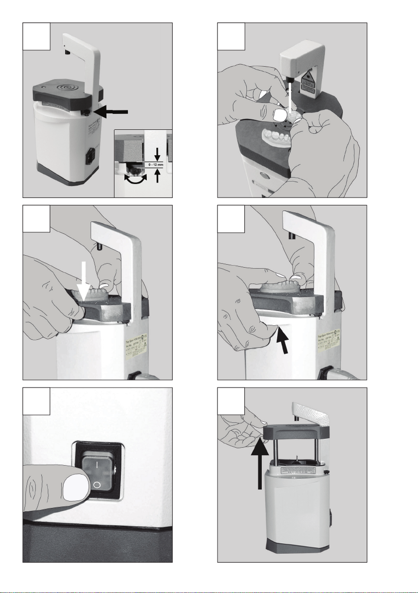
Tischhub: 0 - 12 mm [0 - 0,47 inch],
stufenlos
Schalldruckpegel nach
DIN EN ISO 11202: LpA <70dB(A)
Laser:
Laser-Klasse: 2
Wellenlänge: 630-680nm
Ausgangsleistung P0: max. < 1mW

DE- 5 -
11. Lieferumfang
1 Top spin
1 Stufenbohrer (siehe Skizze 1)
1 Anleitung mit Ersatzteilliste
1 Netzkabel
1 Zubehörset
12. Zubehör
5010-0001 1 Stufenbohrer
(siehe Skizze 1)
367-0000 3 Smart-Pin-Bohrer
(siehe Skizze 2)
Skizze 1
Skizze 2
13. Fehlerliste
Fehler Ursache Abhilfe
Gerät läuft nicht
an.
• Netzversorgung nicht
hergestellt.
• Netzabsicherung
defekt.
• Netzversorgung überprüfen.
• Netzsicherung prüfen.
Bohrungen zu
groß oder un-
rund.
• Bohrer beschädigt oder
verschlissen.
• Bohrfutter nicht fest
genug angezogen.
• Bohrfutter verschmutzt.
• Bohrer austauschen, Bohrfutter
reinigen.
• Bohrfutter handfest anziehen.
• Bohrfutter reinigen.
Mangelnde Bohr-
leistung.
• Bohrer verschlissen. • Bohrer austauschen.
Änderungen vorbehalten.

DE - 6 -

EN- 1 -
Top spin
No. 1835
ENGLISH
1. Introduction
We are pleased that you have decided to
purchase the Top spin pin hole drilling unit.
This unit sets new standards in function,
performance, safety and design.
To ensure that you enjoy using
this product for many years
please take note of the following
instructions.
2. Description / Applications
Top spin is designed to accurately drill
holesforthesecurexationofpinsand
various pin systems within dental techno-
logy.
2.1 Proper use
Top spin is a device for precisely drilling
positionedxtureholesforpinsinplaster
dental models or epoxy resin for a range
of pin systems.
It is exclusively for use in dental facilities.
2.2 Improper use
The product must not be used for drilling
into metals.
The product must not be used for milling.
Breakage of the drill presents a risk of
injury.
Only spare parts and accessories supplied
or authorized by Renfert GmbH may be
used with this product. If other spare parts
or accessories are used, this could have
a detrimental effect on the safety of the
device, increase the risk of serious injury
and lead to damage to the environment or
the device itself.
The protection provided is no
longer assured in the case of im-
proper use and there is a danger
of injury.
2.3 Ambient Conditions
(in accordance with DIN EN
61010-1)
The Top spin may only be operated:
• Indoors;
• Uptoanaltitudeof2,000m[6,500ft]
abovesealevel;
• Atanambienttemperatureof5-40°C
[41-104°F]*);
• Atamaximumrelativehumidityof80%
at 31°C [87.8°F], decreasing linearly to
50%relativehumidityat40°C[104°F]*);
• Withamainspowersupplywherecur-
rentuctuationsdonotexceed10%of
thenominalvalue;
• Underlevel2contaminationconditions;
• UnderovervoltagecategoryIIcondi-
tions.
*) Between 5 - 30°C [41 - 86°F], the unit can be operated at
a relative humidity of up to 80%. At temperatures between
31 - 40°C [87.8 - 104°F], the humidity must decrease
proportionally in order to ensure operational readiness (e.g.,
at35°C[95°F]=65%humidity;at40°C[104°F]=50%
humidity). The unit may not be operated at temperatures
above 40°C [104°F].
3. Areas of Caution
3.1 Employed Symbols
The following symbols are used in these
instructions and on the unit:
Danger
This indicates an imminent risk
of injury.
Electrical hazard
There is a risk of electrical
shock.
Attention
Failure to observe the associ-
ated information can result in
damage to the unit.

EN - 2 -
Note
The operating instructions con-
tain useful information to make
handling easier.
Laser
Do not look into the laser beam!
For indoor use only.
Note the operating instructions.
3.2 Areas of Caution
•Top spin is an electrical appliance
with a danger potential. This appli-
ance may be connected / used only
byauthorizedandqualiedpersons
after checking its conformity with
respect to the national norms.
•Observe the regulations for preven-
tion of accidents of the Employer’s
Liability Insurance Association and
the following safety precautions
when drilling:
•Before switching on always check
the voltage on the unit matches the
voltage supply in your laboratory.
•Units with faulty connections or other
defects should no longer be put into
operation.
•Pull the power plug before working
on the appliance.
•Never reach into the drill when the
unit is connected to the electricity
supply. There is a risk of injury if the
unit is accidentally activated!
•Do not work with the Top spin with
long, untied hair or loose / baggy
clothing. If anything gets tangled up
or drawn in there is a risk of injury.
•The unit is solely designed for dril-
ling plaster or epoxy-resin models.
•Do not touch the drill when in motion.
•The unit should only be activated
when the model is placed in position.
•When drilling do not hold the model
directly over the laser beam - risk of
injury.
Attention!
Laser beam!
Laser class 2
Do not look into the beam!
•It is the responsibility of the opera-
tor that national regulations during
operation and regarding a repeated
safety inspection of electrical equip-
ment are complied with. For Germa-
ny these are BGV A3 in relation with
VDE 0701-0702.
3.3 Liability Exclusion
Renfert GmbH shall be absolved from all
claims for damages or warranty if:
•The product is employed for any pur-
poses other than those cited in the
operating instructions;
•The product is altered in any way
other than those alterations descri-
bed in the operating instructions;
•The product is repaired by other than
an authorized facility or if any but
Renfert OEM parts are employed;
•The product continues to be emplo-
yed, despite obvious safety faults.
4. Installation / Operation
Place the Top spin on a level surface. Two
operating positions are possible:
1. Operation from a standing position =
0° setting (Fig. 1).
2. To change position: turn the housing
base by (Fig. 2).
3. Operation from a sitting position = 16°
setting (Fig. 3).
Check that the voltage in your
laboratory matches the voltage
printedontheidentication
plate.
4. Connect the plug - Top spin (Fig. 4).
5. Connect the plug - mains (Fig. 5).
6. Set the power switch to I (Fig. 6).
7. Check adjustment of drilling depth.
Make a trial boring. Drilling depth can
progressively be adjusted (Fig. 7).
The Top spin is now ready to use.

EN- 3 -
5. Operation / Drilling
1. Focus the laser beam on the model die
(Fig. 8).
2. Holdthediermwithbothhands
(Fig. 8).
3. Motor starts automatically when the
model table is depressed (Fig. 9).
4. For greater pressure use the Top spin
’s counter-balances (Fig. 10).
5. Switch off the Top spin (Fig. 11).
Attention
Do not use Top spin to drill
metal!
Do not use lubricants or cutting
abrasives!
5.1 Changing the drill bit
1. Switch off the Top spin (Fig. 11) and
pull the power plug.
2. Lift the work table and click it into posi-
tion (Fig. 12).
3. Remove the dust bucket (Fig. 13).
4. Set the groove of the drill spindle to
locking pin (Fig. 14).
5. Press the locking pin into the groove of
the drill spindle (Fig. 15) and hold.
6. Loosen the screw cap by turning anti-
clockwise (Fig. 16).
7. Remove the drill bit (Fig. 17) and
replace it with a new one.
8. Hand-tighten the screw cap in a clock-
wise direction (Fig. 18).
9. Replace the dust bucket (Fig. 13).
10. Lower the work table (Fig. 19).
Attention
Use only original Renfert drill
bits!
5.2 Changing of the fuse
1. Switch off the Top spin (Fig. 11) and
pull the power plug.
2. Detach clips at the top and at the bot-
tom (Fig. 22a).
3. Pull out holder together with fuses
(Fig. 22a).
4. Change defect fuse (Fig. 23), for fuse
type see „Technical Data“.
5. Put back the holder together with fuses
(Fig. 22b).
6. Cleaning / Maintenance
Only clean Top spin in a dry state.
1. Switch off the Top spin (Fig. 11).
2. Lift the work table and click it into posi-
tion (Fig. 12).
3. Remove the dust bucket (Fig. 13).
4. Empty the dust bucket and replace it.
5. Lower the work table (Fig. 19).
6.1 Changing or cleaning the
drill spindle
1. Remove the drill bit (see 5.1, points 1
to 7).
2. Loosen the drill spindle by turning
clockwise (Fig. 20).
3. Clean or change the drill spindle.
4. Hand-tighten the drill spindle in an
anti-clockwise direction (Fig. 21).
5. Insert the drill bit (see 5.1, points 8
to 10).
7. Spare Parts
For the order numbers of consumables
and spare parts please refer to the spare
parts list at the end of this manual.

EN - 4 -
8. Guarantee
When used properly Renfert guarantees
all parts of the Top spin for 3 years. In
case of any claims for warranty original
dealers‘ invoice is required. Parts which
are subject to natural wear and tear (wear
parts) and consumables are excluded
from the guarantee. These parts are mar-
ked in the spare part list.
The guarantee is void for damage caused
by misuse, disregard of the instructions for
use, cleaning, maintenance and connec-
tion, for improper self-repaired units or
repair by untrained personnel, for use of
spare parts from other manufacturers and
oninuencesoutsidethenormalpractice
or unauthorized in the instruction manual.
Servicing made under guarantee does not
extend the guarantee.
9. Disposal instructions for
countries in the EU
To conserve and protect the environment,
prevent environmental pollution and
improve the recycling of raw materials, the
European Commission adopted a directive
that requires the manufacturer to accept
the return of electrical and electronic units
for proper disposal or recycling.
Within the European Union units with this
symbol should not therefore be disposed
of in unsorted domestic waste:
For more information regarding proper
disposal please apply at your local authori-
ties.
10. Technical Data
Voltage: 230 V, 50 Hz
115 V, 60 Hz
Power consumption: 150 W
Fuse:
1835-0000 (230V/50Hz):
M1A (1A, medium slow)
1835-4000 (115V/60Hz):
M2A (2A, medium slow)
Revolutions: 16000 1/min.
Dimensions (BxHxD): 166 x 322 x 149 mm
[6.54 x 12.69 x 5.87 inch]
Weight: 5 kg
Drill type: HM-drill with shaft-Ø 3 mm
[0,12 inch]
Table hub: 0 - 12 mm [0 - 0.47 inch],
innitelyvariable
Level of noise pressure according to
DIN EN ISO 11202: LpA < 70dB(A)
Laser:
Laser-Class: 2
Wavelength: 630-680nm
Power output P0: max. < 1mW
11. Parts Supplied
1 Top spin
1 stepped drill bit (see drawing 1)
1 instruction manual with spare parts list
1 mains cable
1 set of hardware

EN- 5 -
12. Accessories
5010-0001 1 stepped drill bit
(see drawing 1)
367-0000 3 Smart-Pin drill bits
(see drawing 2)
Drawing 1
Drawing 2
13. Troubleshooting Guide
Fault Cause Remedy
• The unit does
not switch on.
• The electricity supply
is not properly con-
nected.
• The electrical safety
device is faulty.
• Check the electricity supply.
• Check the electrical safety device.
• The drill holes
are too big or
not round.
• The drill bit is damaged
or worn.
• The drill jig is not tight
enough.
• Chuck dirty.
• Replace the drill bits, clean the
drill jig.
• Tighten the jig by hand.
• Cleaning chuck.
• The drilling is
not effective.
• The drill bit is worn. • Replace the drill bit.
Subjecttomodication.

EN - 6 -

FR- 1 -
Top spin
No. 1835
FRANCAIS
1. Introduction
Nous vous félicitons d’avoir acheté
l’appareil de forage pour pins Top spin qui
va vous apporter un nouveau standard,
que ce soit au niveau du fonctionnement,
des performances, de la sécurité et de la
conception.
An que vous puissiez travailler
longtemps sans problème, nous
vous prions de vous conformer
aux indications ci-dessous.
2. Description / Applications
Le Top spin est un appareil de forage qui
permetdepositionneretdexerexacte-
ment les pins de
différents systèmes, utilisés dans les labo-
ratoires de prothèses dentares.
2.1 Utilisation conforme à la
prescription d‘emploi
Le Top spin est un appareil de forage pour
positionner exactement dans les trous
dexation,lespinssurlesmodèlesen
plâtre ou en résine époxide, des différents
systèmes de pins.
Son emploi ne se fait exclusivement que
dans les ateliers de la technique dentaire.
2.2 Utilisation non conforme à
la prescription d‘emploi
L‘appareil ne doit pas être utilisé pour
perforer du métal.
L‘appareil ne doit pas être utilisé pour frai-
ser. Lors de la cassure du foret un danger
de blessure existe.
Seuls les accessoires et pièces de
rechange fournis ou autorisés par la socié-
té Renfert GmbH peuvent être utilisés
avec ce produit. L‘utilisation d‘autres
accessoires et pièces de rechange peut
compromettre la sécurité de l‘appareil,
présente un risque de blessures graves,
peut causer des dégâts à l‘environnement
ou endommager le produit.
.
Lors d‘un usage contraire à la
prescription d‘emploi, la protec-
tion prévue n‘est plus garantie et
il existe un risque de blessure.
2.3 Conditions d’environnement
(selon la DIN EN 61010-1)
Le Top spin ne peut être utilisé que:
• àl’intérieurd’unepièce,
• jusqu’àunehauteurde2.000mau-
dessus du niveau de la mer,
• àunetempératureambiantede5-40°C
[41-104°F] *),
• àunehumiditémaximalerelativede
80% à 31°C [87,8°F], diminuant linéaire-
ment jusqu’à 50% de l’humidité relative
à 40°C [104°F] *),
• avecunealimentationparsecteur,siles
variations de tension ne sont pas au-
delà de 10% de la valeur nominale,
• avecundegré2depollution,
• avecunesurtensiondelacatégorieII.
*) à une température ambiante de 5 - 30°C [41-86°F] l’appareil
est opérationnel avec un degré d’humidité atmosphérique
allant jusqu’à 80%. A des températures de 31 - 40°C
[87,8-104°F] l’humidité doit diminuer proportionnellement
pour garantir un bonne disponibilité opérationnelle (par
ex.: avec 35°C [95°F] = 65% d’humidité d’ humidité
atmosphérique, à 40°C [104°F] = 50% d’humidité
atmosphérique. A une température au-dessus de 40°C
[104°F] l’appareil ne doit pas être mis en marche.
3. Consignes de sécurité
3.1 Symboles utilisés
Vous trouverez dans cette instruction
de service et sur l’appareil les symboles
suivants:

FR - 2 -
Danger
Il existe le risque direct de bles-
sures.
Tension électrique
Il y a un danger en raison de
tension électrique.
Attention
Lors de la non-observation
des indications il y a risque
d’endommager l’appareil.
Indication
Donne une recommandation
utile, facilitant la manipulation
de l’appareil.
Laser
Ne pas regarder dans le rayon
laser!
Utilisation uniquement à
l’intérieur de locaux.
Tenir compte du mode d’emploi.
3.2 Consignes de sécurité
•Pour ce qui est du Top spin il s’agit
d’un appareil électrique avec un
potentiel de danger. Cet appareil ne
doit être raccordé / utilisé que par un
personnel autorisé compétent après
véricationdelaconformitédesnor-
messpéciquesdupays.
•Respecter les instructions préven-
tives du syndicat professionnel
contre les accidents et se conformer
pour le forage aux consignes de
sécurité.
•Avant la mise en marche comparer la
tension secteur avec celle indiquée
sur l’appareil.
•Les appareils ayant des câbles
d’amenée abîmés ou d’autres défauts
ne doivent pas être mis en marche.
•Avant de faire des travaux de monta-
ge enlever la prise du secteur.
•Lorsque l‘alimentation en courant est
faite, ne pas toucher au foret. Lors
de la mise en marche soudaine de
l’appareil il y a risque de blessures!
•Ne pas travailler sur le Top spin avec
des cheveux longs non attachés ou
des vêtements ouverts ou larges.
Leur prise et leur enroulement dans
l’appareil provoqueraient des bles-
sures.
•L’appareil n’a été construit que pour
le forage de modèles en plâtre ou en
résine epoxy.
•Ne jamais toucher au foret lorsqu’il
tourne.
•Le maniement de l’appareil ne se fait
qu’avec des modèles soutenus.
•Lors du forage ne pas tenir directe-
ment sur le point laser projeté. Ris-
que de blessures.
Attention!
Rayon laser!
Laser de la classe 2
Ne pas regarder dans le rayon!
•L’observation des prescriptions
nationales concernant le service et la
véricationdesécuritérépétitivedes
appareils électriques est la respon-
sabilité d’opérateur. En Allemagne
cela est la BGV A3 en relation avec la
norme VDE 0701-0702.
3.3 Exclusion de responsabilité
Renfert GmbH déclinera tout droit
d’indemnisation et de garantie si:
•le matériel a été utilisé dans
d’autres buts que ceux décrits dans
l’instruction de service.
•le matériel a été d’une façon ou d’une
autre transformé - à l’exception des
modicationscitéesdanslemode
d’emploi.
•l’appareil a été réparé par une perso-
nne non autorisée, ou dans le cas où
les pièces détachées ne seraient pas
d’origine Renfert.
•le matériel a été utilisé alors qu’il pré-
sentait des défauts de sécurité.
Other manuals for TOP spin
3
This manual suits for next models
2
Table of contents
Languages:
Popular Dispenser manuals by other brands

Hewi
Hewi 477 Series Mounting instructions

Whitmore
Whitmore OilSafe Tote Dispensing System owner's manual

EFBE-SCHOTT
EFBE-SCHOTT GW 900 operating instructions

Franke
Franke STRX616 Installation and operating instructions

ZIPPY
ZIPPY TSPD-01 quick start guide

Wausau Paper
Wausau Paper Alliance series user guide