Renogy REC500CB-98 User manual

USER MANUAL
500A Combiner Box
Renogy
(Standard Version)
VERSION A0
REC500CB-98


Before Getting Started
The user manual provides important operation and maintenance instructions for
Renogy 500A Combiner Box (hereinafter referred to as combiner box).
Read the user manual carefully before operation and save it for future reference.
Failure to observe the instructions or precautions in the user manual can result in
electrical shock, serious injury, or death, or can damage the combiner box, potentially
rendering it inoperable.
zRenogy ensures the accuracy, sufficiency, and the applicability of information in
the user manual at the time of printing due to continual product improvements
that may occur.
zRenogy assumes no responsibility or liability for personal and property losses,
whether directly and indirectly, caused by the user’s failure to install and use the
product in compliance with the user manual.
zRenogy is not responsible or liable for any failure, damage, or injury resulting from
repair attempts by unqualified personnel, improper installation, or inappropriate
operation.
zThe illustrations in the user manual are for demonstration purposes only. Details
may appear slightly different depending on product revision and market region.
zRenogy reserves the right to change the information in the user manual without
notice. For the latest user manual, visit renogy.com.
Disclaimer
Renogy 500A Combiner Box User Manual © 2023 Renogy. All rights reserved.
RENOGY and are registered trademarks of Renogy.
zAll information in the user manual is subject to copyright and other intellectual
property rights of Renogy and its licensors. The user manual may not be modified,
reproduced, or copied, in whole or in part, without the prior written permissions of
Renogy and its licensors.
zThe registered trademarks in the user manual are the property of Renogy. The
unauthorized use of the trademarks is strictly prohibited.
Online Manual
User Manual

Symbols Used ...................................................................................................................1
Introduction .....................................................................................................................1
Key Features.....................................................................................................................1
SKU ....................................................................................................................................1
What’s In the Box?........................................................................................................... 2
Required Tools & Accessories ....................................................................................... 2
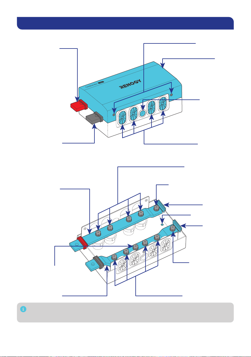
Get to Know Renogy 500A Combiner Box .................................................................... 3
Wiring Diagram ................................................................................................................ 4
Use MRBF Fuse.......................................................................................................................... 4
Use ANL Fuse............................................................................................................................. 5
Dimensions ...................................................................................................................... 5
How to Size Cables?........................................................................................................ 6
How to Install the 3/8 in Lugs (M10 Ring Terminals)? ................................................ 6
How to Connect Energy Devices to the Busbars Safely?........................................... 7
Step 1. Plan a Mounting Site .......................................................................................... 8
Step 2. Wear Insulating Gloves...................................................................................... 8
Step 3. Remove the Cover.............................................................................................. 8
Step 4. Mount the Combiner Box .................................................................................. 9
Step 5. Ground the Combiner Box................................................................................. 9
Step 6. Connect Energy Devices to the Combiner Box............................................. 10
Use MRBF Fuse........................................................................................................................ 10
Use ANL Fuse........................................................................................................................... 12
Step 7. Install the Cover ............................................................................................... 13
Interconnecting Combiner Boxs................................................................................. 13
Specifications ............................................................................................................... 15
Maintenance.................................................................................................................. 16
Important Safety Instructions ....................................................................................17
General .......................................................................................................................................17
Combiner Box Safety...............................................................................................................17
Renogy Support ............................................................................................................ 18
Table of Contents

— 1 —
Symbols Used
The following symbols are used throughout the user manual to highlight important
information.
WARNING: Indicates a potentially dangerous condition which could result in injury
or death.
CAUTION: Indicates a critical procedure for safe and proper installation and
operation.
NOTE: Indicates an important step or tip for optimal performance.
Introduction
The Renogy 500A Combiner Box is equipped with two busbars (a negative and a
positive) that offer four connections for batteries, loads, or battery chargers, along with
a ground connection. It also allows for easy expansion of the system by connecting the
box to other combiner boxes through the extend terminals.
This combiner box is compatible with general batteries (12V, 24V, 36V, and 48V),
inverters, charge controllers, and battery chargers.
Key Features
zSafety and Stability
The combiner box is equipped with two busbars and supports the installation of
fuses, especially Marine Rated Battery (MRBF) fuses, to ensure electrical safety.
This also simplifies installation and maintenance with quicker installation and less
effort.
zCompact and Lightweight Design
The combiner box is compact and lightweight, making it easy to install in any
location, while also providing sufficient internal space to accommodate thick wires
and larger terminals.
zSturdy Outer Casing
The combiner box protects the system connections with a sturdy outer casing,
which remains intact even when subjected to wire bending or twisting.
zLong-Time Stable Running
The high-quality tin-plated copper busbars inside ensure the system operates
reliably for extended periods.
SKU
Renogy 500A Combiner Box REC500CB-98

— 2 —
What’s In the Box?
USER MANUAL
500A Combiner Box
Renogy
(Standard Version)
VERSION A0
REC500CB-98
Renogy 500A Combiner Box × 1
User Manual × 1
Long Terminal Bolts × 4Insulating Sleeves × 4
M8 x 35 mm
Make sure the combiner box is free of any signs of damage.
Required Tools & Accessories
3/8 in Lugs
(M10 Ring Terminals)
Insulating Gloves Phillips
Screwdriver (#2)
Wire Stripper Manual
Hydraulic Pliers
Bare Wires
Self-tapping
Screws x 4
ST6.3
Wrench
(17/32 in)
13mm
13mm
13mm
Prior to installing and configuring the combiner box, prepare the recommended
tools, components, and accessories.
For how to size bare wires, refer to “How to Size Cables?” in this manual.
Choose proper mounting screws specific to your installation site. This manual
takes self-tapping screws for wooden walls as an example.

— 3 —
Get to Know Renogy 500A Combiner Box
█Exterior
Positive Busbar
Dust Cover
Negative Busbar
Dust Cover
Ground Port
Cables Ports
Cover Screws
Cover
█Interior (with the cover removed)
Positive Terminals
Negative Terminals
Extend Negative
Terminal
Dust Cover
Mounting Holes
Positive Busbar
Negative Busbar
Ground Terminals
Dust Cover
Extend Positive Terminal
Each busbar terminal is equipped with a terminal bolt, a spring washer, and a flat
washer.

— 4 —
Wiring Diagram
The continuous current flowing through the combiner box shall not exceed 500A.
The voltage is within the range of 9V to 60V.
The wiring diagram only shows the key components in a typical DC-coupled
residential energy storage system for the illustrative purpose. The wiring might
be different depending on the system configuration. Additional safety devices,
including disconnect switches, emergency stops, and rapid shutdown devices,
might be required. Wire the system in accordance with the regulations at the
installation site.
Use MRBF Fuse
MRBF Fuse
Charge
Controller
Battery Battery
Charger
+
-
+
-
Positive
Negative
Ground
Inverter
Charger
Combiner BoxGroundingDevices (9V–60V, 500A Max)
DC LoadsDC Distribution
Panel or Converter

— 5 —
Use ANL Fuse
Charge
Controller
Battery Battery
Charger
+
-
+
-
Positive
Negative
Ground
ANL Fuse
Inverter
Charger
Combiner Box
GroundingDevices (9V–60V, 500A Max)
DC LoadsDC Distribution
Panel or Converter
Dimensions
10.35 in (263 mm)
6.30 in
(160 mm)
3.94 in
(100 mm)
Dimension tolerance: ±0.2 in (0.5 mm)

— 6 —
How to Size Cables?
Size wires specific to the operating current of relevant devices. Refer to the table below
for copper cable ampacities with different gauge sizes.
Cable Gauge Size Ampacity Cable Gauge Size Ampacity
14 AWG (2.08 mm²) 35A 2 AWG (33.6 mm²) 190A
12 AWG (3.31 mm²) 40A 1 AWG (42.4 mm²) 220A
10 AWG (5.25 mm²) 55A 1/0 AWG (53.5 mm²) 260A
8 AWG (8.36 mm²) 80A 2/0 AWG (67.4 mm²) 300A
6 AWG (13.3 mm²) 105A 4/0 AWG (107 mm²) 405A
4 AWG (21.1 mm²) 140A
The above values are from the NEC Table 310.15(B)16 for copper cables rated at
167°F (75°C), operating at an ambient temperature of no more than 86°F (30°C).
Cables longer than 6 feet (1829 mm) may require thicker gauge wires to prevent
excessive voltage drop in undersized wiring.
How to Install the 3/8 in Lugs (M10 Ring Terminals)?
21
43
0.4 in (10 mm)

— 7 —
How to Connect Energy Devices to the Busbars Safely?
1
3
2
4 5
Positive
Negative
Keep a safe distance
between the positive
terminal and the
negative busbar.
Avoid contact between
the positive terminal
and the negative
busbar.
Ensure that the positive busbar terminal does not come into contact with the
negative busbar terminal. Short circuits can damage connected batteries and
devices.

— 8 —
Step 1. Plan a Mounting Site
Install the combiner box in a clean, cool, and dry place. Keep water, oil, and dirt away
from the combiner box, and protect it from direct sunlight.
KEEP DRY INDOOR VENTILATION
-4°F to 140°F
-20°C to 60°C
0% to 99%
Vent
Vent Enclosed space
Air
cross-flow
The combiner box can be mounted either on a floor or on a wall.
Step 2. Wear Insulating Gloves
Insulating
Gloves
Step 3. Remove the Cover

— 9 —
Step 4. Mount the Combiner Box
0.27 in
(7 mm)
0.27 in
(7 mm)
30.98 in·lbs
(3.5 N·m)
Make sure that the combiner box is installed firmly to prevent it from falling off.
Inspect the combiner box for any visible damage including cracks, dents,
deformation, and other visible abnormalities. All terminal contacts shall be clean,
free of dirt and corrosion, and dry.
Step 5. Ground the Combiner Box
Grounding
Bare Wire
Terminal Bolt
70.8 in·lbs
(8 N·m)
Through the grommet
of the Ground Port

— 10 —
Step 6. Connect Energy Devices to the Combiner Box
Install wires on energy devices (charge controller, battery, inverter, and more) prior
to connecting them to the combiner box. For details on how to install wires on the
devices, see the user manual of the specific device. Always install the negative
terminals before positive ones. The following figure takes connecting a REGO 12V 60A
MPPT Solar Charge Controller to the combiner box as an example.
Ensure the cable lug and the busbar terminal are in contact, and place the
washers on top of the lug. Do not place the washers between the busbar terminal
and the cable lug to avoid high resistance and excessive heating.
Ensure that the positive busbar terminal does not come into contact with the
negative busbar terminal. Short circuits can damage connected batteries and
devices.
Check the polarity before connecting the cables. Reverse polarity can damage
connected batteries and devices.
To ensure safe and reliable operation of the system, please follow the torque
specifications of relevant devices recommended by the manufacturer securing
cable connections. Over-tightening can cause terminal breakage, while loose
connections can lead to terminal meltdown or fire hazards.
Use MRBF Fuse
Recommended Components
MRBF Fuse
Choose proper MRBF fuses (not included) to meet specifications of the relevant
devices. For details, see the user manuals of the relevant devices.

— 11 —
STEP-2 Install the MRBF fuse and positive
Long Terminal Bolt
Insulating Sleeve
MRBF Fuse
Charge Controller
Renogy 500A Combiner Box
Through the grommet
of the Cables Port
Bare Wires
+
-
Terminal Bolt
STEP-1 Install the negative
70.8 in·lbs
(8 N·m)
70.8 in·lbs
(8 N·m)

— 12 —
Use ANL Fuse
Recommended Components
ANL Fuse
Choose proper ANL fuses (not included) to meet specifications of the relevant
devices. For details, see the user manuals of the relevant devices.
Charge Controller
Renogy 500A Combiner Box
Through the grommet
of the Cables Port
+
-
Terminal Bolt
STEP-1 Install the negative
Terminal Bolt
STEP-3 Install the positive
STEP-2 Install an ANL fuse
70.8 in·lbs
(8 N·m)
70.8 in·lbs
(8 N·m)
70.8 in·lbs
(8 N·m)
ANL Fuse
Bare Wires
Bare Wires

— 13 —
Step 7. Install the Cover
14.16 in·lbs
(1.6 N·m)
Interconnecting Combiner Boxs
Step 1: Remove the dust covers and extend positive/negative terminals from the
first combiner box. Similarly, remove the dust covers from the positive and negative
busbars from the second combiner box.
First Combiner Box Second Combiner Box

— 14 —
Step 2: Align the busbar ports.
First Combiner Box
Second
Combiner Box
Step 3: Install the terminal bolts, spring washers, and flat washers on the busbar ports.
Terminal Bolt
70.8 in·lbs
(8 N·m)

— 15 —
Specifications
Voltage Range 9V to 60V DC
Rated Current 500A
Connector M8 Busbar
Enclosure Material Sheet Metal
Enclosure Dimensions 10.35 x 6.30 x 3.94 in
263 x 160 x 100 mm
Weight 5.73 lbs. / 2.6 kg
Busbar Material Tinned Copper
Busbar Dimensions 0.31 x 1.18 in
8 x 30 mm
Recommended Terminal Torque 70.8 in·lbs / 8 N·m
Operating Temperature Range -4°F to 140°F / -20°C to 60°C
Storage Temperature Range -40°F to 176°F / -40°C to 80°C
Humidity 0-99% RH (non-condensing)
Protection Class IP22

— 16 —
Maintenance
Inspection
Please perform regular inspections following the steps below:
zExamine the external appearance of the combiner box. The casing and terminals of
the combiner box shall be clean, dry, and free of corrosion.
zCheck the continuity of the fuses. Replace any blown fuses.
zCheck the cables and connections. Replace any damaged cables and tighten any
loose connections.
In certain application scenarios, corrosion may occur around the terminals.
Corrosion can cause increased resistance and poor contact. It is recommended
to regularly apply insulation grease to each terminal. Insulation grease can form
a moisture-resistant seal and protect the terminals from corrosion.
Cleaning
Please clean the combiner box at regular intervals following the steps below.
zDisconnect the devices and batteries or battery combiner box from the combiner
box.
zClean the casing and terminals. The household cleaner can be used if the combiner
box is extremely dirty.
zUse a clean cloth to dry the combiner box. Ensure that the area surrounding the
combiner box remains clean and dry.
zReconnect the necessary devices to the combiner box.
Table of contents
Other Renogy Power Supply manuals